EP2033885A1 - Ensemble de protection latérale pour motocyclette et motocyclette équipée d'un tel ensemble de protection latérale - Google Patents
Ensemble de protection latérale pour motocyclette et motocyclette équipée d'un tel ensemble de protection latérale Download PDFInfo
- Publication number
- EP2033885A1 EP2033885A1 EP07017317A EP07017317A EP2033885A1 EP 2033885 A1 EP2033885 A1 EP 2033885A1 EP 07017317 A EP07017317 A EP 07017317A EP 07017317 A EP07017317 A EP 07017317A EP 2033885 A1 EP2033885 A1 EP 2033885A1
- Authority
- EP
- European Patent Office
- Prior art keywords
- motorcycle
- side cover
- assembly
- cover elements
- fixed
- Prior art date
- Legal status (The legal status is an assumption and is not a legal conclusion. Google has not performed a legal analysis and makes no representation as to the accuracy of the status listed.)
- Granted
Links
Images


Classifications
-
- B—PERFORMING OPERATIONS; TRANSPORTING
- B62—LAND VEHICLES FOR TRAVELLING OTHERWISE THAN ON RAILS
- B62J—CYCLE SADDLES OR SEATS; AUXILIARY DEVICES OR ACCESSORIES SPECIALLY ADAPTED TO CYCLES AND NOT OTHERWISE PROVIDED FOR, e.g. ARTICLE CARRIERS OR CYCLE PROTECTORS
- B62J23/00—Other protectors specially adapted for cycles
-
- B—PERFORMING OPERATIONS; TRANSPORTING
- B62—LAND VEHICLES FOR TRAVELLING OTHERWISE THAN ON RAILS
- B62J—CYCLE SADDLES OR SEATS; AUXILIARY DEVICES OR ACCESSORIES SPECIALLY ADAPTED TO CYCLES AND NOT OTHERWISE PROVIDED FOR, e.g. ARTICLE CARRIERS OR CYCLE PROTECTORS
- B62J17/00—Weather guards for riders; Fairings or stream-lining parts not otherwise provided for
- B62J17/02—Weather guards for riders; Fairings or stream-lining parts not otherwise provided for shielding only the rider's front
Definitions
- the present invention relates to the field of motorcycles.
- the present invention relates to a side cover assembly for a motorcycle and a respective motorcycle equipped with such a side cover assembly.
- the present invention relates to a side cover assembly comprising side cover elements adapted to be mounted to a motorcycle on opposite sides thereof.
- the present invention relates to the purpose to be exploited by said side cover elements and to the way said side cover elements are mounted to and removed from a motorcycle.
- said side cover elements in the following also referred to as covering elements
- said side cover elements once mounted to the motorcycle will influence not only the overall look and appearance of said motorcycle, but also its aerodynamic or the like, which will therefore, influence the overall performance of the motorcycle in terms of speed and fuel consumption.
- special attention has also to be paid to the way this protecting and/or covering elements will be mounted to the motorcycle and removed there from as the need arises.
- the mounting process or operation would reveal to be unduly long and/or troublesome
- assembly of the overall motorcycle could also reveal to be difficult and/or troublesome, resulting in the assembly operation being unduly elongated, so that the production and manufacturing costs would also unduly increase, accordingly.
- a further question arising during the design of side covering elements relates to the resistance to be offered by said side covering elements to eventual impact, shock or the like. It has in fact to be decided which impacts the side covering elements shall resist to and which impacts shall result in the side covering elements becoming broken or damaged.
- HTS high tensile steel
- the main frame had to be designed ad hoc so as to be adapted to cooperate with said side covering elements, in particular so as to provide and/or offer adequate anchoring points for the side covering elements.
- heavy and bulky side covering elements have the further disadvantage that, as soon as the need arises to gain access to component parts and/or equipment located behind the side covering elements (for instance below the fuel tank) for maintenance purposes, the side covering elements (or at least one of them) have to be removed from the motorcycle otherwise the access to said equipment would be obstructed by the side covering elements.
- removing bulky and heavy side covering elements may be revealed to be a very long and difficult task, especially if special anchoring means are provided for the purpose of anchoring said side covering elements to the frame of the motorcycle.
- the anchoring points are usually not easily accessible.
- a further disadvantage affecting the prior art side covering elements relates to the fact that even, on the one hand, adequate protection is offered so that equipment of the motorcycle does not become easily damaged, on the other hand, even in the case of normal impact or shock, said side covering elements do become damaged, so that they have to be substituted.
- large and heavy side covering elements for instance made of high tensile steel are quite expensive so that increased costs occur also in the case of normal impact.
- violent impact not only the side covering elements become damaged, but also the equipment to be protected or at least some of them, so that additional costs arise.
- an object of the present invention to provide a solution allowing to overcome the problems as stated above.
- a further object of the present invention is that of providing side covering elements adapted to be quickly mounted to, and removed from a plurality of motorcycles of different kind and/or appearance.
- a still further object of the present invention is that of providing side covering elements offering adequate protection for equipment and/or accessories of a motorcycle once said side covering elements have been mounted thereto.
- a further object of the present invention is that of providing side covering elements allowing easy access to at least some equipment of said motorcycle located behind said side covering elements, even without being requested to remove said side covering elements from the motorcycle.
- a further object of the present invention is that of providing side covering elements of reduced dimensions and weight but still providing a convenient protection and/or resistance to at least normal impacts.
- it is another object of the present invention that of providing side covering elements which do not negatively influence the overall look, appearance and aerodynamics of the motorcycle but even allows the overall appearance and aerodynamics of the motorcycle to be improved.
- the present invention is based on the consideration that the problems affecting the prior art solutions, in particular the prior art side covering elements may be overcome if a convenient way to anchor or fix said side covering elements to the motorcycle is provided.
- a further consideration on which the present invention is based relates to the fact that, if a convenient location for the anchoring or fixing points is provided, then adequate protection is offered, along with an easy way to mount and to remove said side covering elements to and from the motorcycle.
- Another consideration on which the present invention is based relates to the fact that an adequate and convenient balance between protection offered, overall appearance and aerodynamic, easy mounting and simplified access to equipment of the motorcycle can be found if side covering elements of predefined dimensions and shape are fixed, at least partially, to some of the equipment or component parts of the motorcycle to be protected. In fact, in this way, the need to design special frames for the purpose of anchoring the side covering elements no longer arises. Accordingly, the side covering elements may be mounted to a plurality of different motorcycles.
- the costs of the side covering elements may be kept low and the assembly operations may be speeded up. Furthermore, access to at least some of the equipment of the motorcycle may be obtained even without removing first the side covering elements. Moreover, once the side covering elements become damaged, for instance due to an impact or shock, substituting said side covering element do not reveal to be too expensive. Finally, adequate protection in case of normal impacts or shocks is still provided.
- the present invention is understood to be of particular advantage when applied to motorcycles such as, for instance, motorbikes.
- examples will be given in the following, in which corresponding embodiments of the side cover assembly according to the present invention are applied to motorbikes.
- the applications of the side cover assembly according to the present invention are not limited to the case of motorbikes.
- the side cover assembly according to the present invention may also be applied to other motorcycles and/or motor vehicles, in particular to three or even four-wheeled motorcycles such as, for instance choppers, quads or the like.
- the applications of the side cover assembly according to the present invention are even not limited to the particular kind of motorbikes depicted in the drawings.
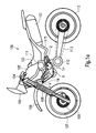
- FIGs 1a and 1b a motorcycle 100 is depicted. Although in Figures 1 and and 1b some portions or component parts or even accessories or equipments common to usual motorcycles have not been depicted or even identified by reference numerals, the essential features of common motorcycles may be recognized when looking at Figures 1a and 1b . These features relate in particular to a front and a rear wheel 107, 112, with said front wheel 107 comprising a brake disc 109 and being supported by a front fork 108; said front fork 108 supports moreover a front fender 106 provided to avoid the driver and/or passenger or even the motorcycle 100 from being splashed with mud, water or the like lying on the bottom.
- the motorcycle 100 depicted in Figures 1 and 1b further comprises a fuel tank 103, a seat 102, and a silencer 101 extending from an exhaust gas pipe 115.
- a handlebar 104 Depicted in Figures 1a and 1b is also a handlebar 104 provided with brake handles and corresponding cables extending therefrom.
- a front cowling assembly 105 is mounted to the front portion of the motorcycle 100, with said front cowling assembly 105 being adapted to support equipment of the motorcycle 100 such as, for instance, a speedometer, a fuel level indicator, oil pressure indicator, headlights, front direction indicators or the like.
- a chain 113 extends from a crank case 110 to the rear wheel 112, said chain 113 transmitting driving force from the crank case 110 to the rear wheel 112.
- the reference numeral 111 identifies the engine (or parts thereof) of the motorcycle 100 depicted therein; said component parts may comprise the cylinder or the like. Since further details of the engine 111 are not strictly essential to the present invention, a further detailed description of said further details may be omitted for the sake of convenience.
- the motorcycle 100 depicted in Figures 1a and 1b further comprises a radiator or cooling system 114 which will be described in detail in the following.
- the side cover assembly according to the present invention comprises a first side cover element 1l and a second side cover element 1r, adapted to be mounted to the motorcycle on opposite sides thereof.
- the first side cover element 1l is mounted to the left side of the motorcycle 100 by means of mounting and/or fixing means 1lf and 1lr
- the second side cover element 1r is mounted to the right side of the motorcycle, still by means of mounting and/or fixing means 1rf and 1rr.
- first and second side cover elements 1l and 1r are mounted to one or more components of the motorcycle 100.
- first and second side cover elements 1l and 1r are mounted to components or equipment of the motorcycle 100 located substantially below the fuel tank 103 and in proximity of the cylinder (not explicitly depicted in the drawings) of the motorcycle 100.
- this solution offers easy mounting of the side cover elements 1l and 1r to the motorcycle 100, since it is not necessary to provide for instance a special main frame of the motorcycle adapted to this end.
- the side cover elements 1l and 1r offer adequate protection for the equipment located in the space defined by said side cover elements in combination, at least in case of normal impact and shocks. Furthermore, the reduced dimension of the side cover elements 1l and 1r allows easy access to the equipment of the motorcycle located below the fuel tank 103 and/or in proximity of the cylinder of the motorcycle 100; in particular, this is obtained due to the particular shape of the side cover elements 1l and 1r which, as apparent from Figures 1a and 1b is substantially elongated and curved toward the top, so that enough space is left to an operator requested to work on equipment and/or accessories of the motorcycle located between the first and second side cover elements 1l and 1r.
- each of the side cover elements 1l and 1r easy access is also offered by through apertures provided in each of the side cover elements 1l and 1r.
- one or both the side cover elements 1l and 1r may be removed and repaired or substituted, at a low cost and according to simple and quick operations.
- first side cover element 1l namely the side cover element adapted to be mounted to the left side of a motorcycle as depicted in Figure 1a .
- Said first left side cover element 1l comprises a front portion 1l1 and a rear portion 1l2 with said front and rear portions 1l1 and 1l2 extending from a central portion of the side cover element 1l.
- the front end portion 1l1 extends from the central portion so as to face towards the front of the motorcycle once the side cover element 1l has been mounted to the motorcycle as depicted in Figure 1 ; on the contrary, the rear end portion 112 extends from the central portion so as to face toward the rear of the motorcycle once the side cover element 1l has been mounted to the motorcycle as depicted in Figure 1a . Moreover, the rear end portion 1l2 extends from the central portion substantially horizontally or so as to be slightly inclined toward the top.
- the front end portion 1l1 extends from the central portion at a predetermined angle; in particular as apparent from Figure 2a , the front end portion 1l1 is inclined so as to face toward the top and the front of the motorcycle once the side cover element 1l has been mounted to the motorcycle 100 as depicted in Figure 1a .
- the respective inclination of the front and rear end portions 1l1 and 1l2 or, in other words the direction along which said front and rear end portions 1l1 and 1l2 extend from the central portion confers to the first left side cover element 1l a slightly curved shape. It is this slightly curved shape which allows to gain easy access to the components and/or equipment of the motorcycle 100 located behind said first left cover element 1l.
- the through aperture 1la provided in the front end portion 1l1 of the first side cover element 1l.
- the shape and dimension of said through aperture 1la may be selected according to the exigencies and/or circumstances; that is to say, that shapes other than the substantially rectangular shape depicted in Figure 2a may be selected for the through aperture 1la, along with convenient dimensions.
- the thickness of the first side cover element 1l may also be selected according to the circumstances and for instances depending thereon which protection has to be obtained or which resistance the side cover element 1l shall offer to impacts, shocks or the like. It is also possible to select different thicknesses for corresponding different portions of the side cover element 1l; for instance, according to the embodiment depicted in Figure 2a , the thickness of the rear end portion 112 of the side cover element 1l depicted therein is larger or more than the thickness of the front end portion 1l1.
- reference numeral 1lf identifies front screwing means
- reference numerals 1lr identifies corresponding rear screwing means. Said front and rear screwing means 1lf and 1lr allows the side cover element 1l to be mounted to the motorcycles so as to be firmly fixed thereto and may comprise screws, bolts or the like.
- an exhaust gas pipe 115 extends from the engine 111 (for instance from the cylinder) towards the rear of the motorcycle so as to be at least partially located besides the engine or cylinder 111.
- Said exhaust gas pipe 115 comprises in particular a first and a second pipe 115u and 115l which join together so as to form a single pipe 1ls extending toward the rear of the motorcycle.
- a protective element 2 is furthermore provided, with said protective element 2 being placed on said gas pipe115 (partially on said pipes 115u, 115l and 100ls) so as to be firmly fixed thereto.
- the way the protective element 2 is fixed to the exhaust gas pipe 115 or parts thereof may be selected according to the circumstances; for instance, to this end fixing means such as clips or the like may be used.
- the protective element 2 may be welded to the exhaust gas pipe 115.
- the protective element 2 further comprises rear fixing means 2f adapted to cooperate with the rear screwing means 1lr depicted in Figure 2a .
- a plate 114p extends from the radiator 114 (or a cover thereof), with said protruding plate 114p being located in proximity to the left end portion of said radiator 114 and comprising front fixing means 114pl.
- Said rear and front fixing means 2f and 114pl may comprise holes or recesses with an internal screw so as to be adapted to receive the screwing means 1lf and 1lr, respectively.
- screwed bushes or the like may be provided.
- the left side cover element 1l is therefore mounted to the left side of the motor cycle by fixing the front end portion 1l1 of said side cover element 1l to the plate 114p extending from the radiator 114 (or a cover thereof) by means of the front screwing means 1lf screwed into the corresponding fixing means 114pl, whilst the rear end portion 1l2 of the side cover element 1l is fixed to the protective element 2 by means of the rear screwing means 1lr received and screwed into the corresponding screwed holes or bushes 2f.
- FIG 3a there is depicted in particular a second side cover element 1r, namely the right side cover element adapted to be mounted to the right side of a motorcycle as depicted in Figure 1b .
- Said second right side cover element 1r comprises a front portion 1r1 and a rear portion 1r2, with said front and rear portions 1r1 and 1r2 extending from a central portion of the side cover element 1r.
- the front end portion 1r1 extends from the central portion so as to face towards the front of the motorcycle once the side cover element 1l has been mounted to the motorcycle as depicted in Figure 1b ; on the contrary, the rear end portion 1r2 extends from the central portion so as to face toward the rear of the motorcycle once the side cover element 1l has been mounted to the motorcycle as depicted in Figures 1b and 3b . Moreover, the rear end portion 1r2 extends from the central portion substantially horizontally or so as to be slightly inclined toward the top.
- the front end portion 1r1 extends from the central portion at a predetermined angle; in particular as apparent from Figure 2b , the front end portion 1r1 is inclined so as to face toward the top and the front of the motorcycle once said right side cover element 1r has been mounted to the motorcycle as depicted in Figures 1b and 3b .
- the respective inclination of the front and rear end portions 1r1 and 1r2 or, in other words the direction along which said front and rear end portions 1r1 and 1r2 extends from the central portion confers to the second right side cover element 1r a light curved shape.
- a through aperture 1ra is provided also in the case of the right side cover element 1r, the shape and dimensions of said aperture 1ra being substantially similar to those of the aperture 1la of the left side cover element 1l. It results therefore that the right side cover element 1r may be provided so as to be substantially similar to the left side cover element 1l as on its shape, configuration, appearance and dimensions. Accordingly, the considerations as stated above relating to the advantages offered by the left side cover element 1l in terms of protection offered, easy access to equipments located behind it and so on, also apply to the right side cover element 1r. However, it has to be noted that even left and right side cover elements differing in shape and/or dimensions may be provided according to the exigencies and/or circumstances, for instance for exploiting different purposes.
- reference numeral 1rf identifies front screwing means
- reference numerals 1rr identifies corresponding rear screwing means.
- Said front and rear screwing means 1rf and 1rr allows the side cover element 1r to be mounted to a motorcycles so as to be firmly fixed thereto and may comprise screws, bolts or the like.
- the motorcycle depicted therein comprises a coolant fluid tank 3 located below the fuel tank and in proximity of the engine or cylinder 111.
- Said coolant fluid or liquid tank 3 further comprises rear fixing means 3f adapted to cooperate with the rear screwing means 1rr depicted in Figure 3a .
- a right plate 114p extends moreover from the radiator 114 (or a cover thereof) with said protruding plate 114p being located in proximity to the right end portion of said radiator 114 and comprising front fixing means 114pr.
- Said rear and front fixing means 3f and 114pr may comprise holes or recesses with an internal screw so as to be adapted to receive the screwing means 1rr and 1rf.
- screwed bushes or the like may be provided to this end.
- the right side cover element 1r is therefore mounted to the right side of the motor cycle in such a way that the front end portion 1r1 of said side cover element 1ris fixed to the plate 114p extending from the radiator 114 (or a cover thereof) by means of the front screwing means 1rf screwed into the fixing means 114pr, whilst the rear end portion 1r2 of the side cover element 1r is fixed to coolant liquid tank 3 by means of the rear screwing means 1rr received into the corresponding screwed holes or bushes 3f.
- a third left side cover element 4l is mounted to the left side of the motorcycle 100; in the same way, as apparent from figure 4b , a fourth right side cover element 4r is mounted to the right side of the motorcycle 100.
- the shape of the third and fourth side cover elements 4l and 4r is selected so as to match with that of the first and second side cover elements 1l and 1r, respectively.
- the third and fourth side cover elements 4l and 4r are fixed to the fuel tank 103 on opposite sides thereof; to this end, front and rear screwing means 4lf and 4lr (for the third left cover element 41), along with front and rear screwing means 4rf and 4rr (for the fourth right cover element 4r) such as screws, bolts or the like may be provided, similar to the screwing means 1lf, 1lr, 1 rf and 1rr used for fixing the first second side cover elements 1l and 1r to the motorcycle.
- corresponding fixing means are mounted to the fuel tank on opposite sides thereof, with said fixing means being adapted to cooperate with said screwing means 4lf, 4lr, 4rf and 4rr, respectively, in particular being adapted to receive said screws or bolts.
- screwed holes or bushes similar to those provided on the protective element 2 and the coolant liquid tank 3 may be used.
- the embodiment depicted in Figures 4a and 4b may be preferred in those circumstances in which a better protection has to be reached and/or obtained.
- most of the advantages offered by the embodiment depicted in Figures 1a , 1b , 2a to 2c and 3a to 3c are still offered by the embodiment depicted in Figures 4a and 4b .
- one or both of the side cover elements 4r and 1r may be removed.
- the side cover assembly according to the present invention allows to overcome or at least to strongly reduce or minimize the drawbacks effecting the prior art side cover assemblies.
- the side cover assembly according to the present invention allows the side cover elements to be quickly and easily mounted to and removed from the motorcycle. Moreover, adequate protection is still offered, without the overall look, appearance and aerodynamic of the motorcycle being negatively affected or influenced. On the contrary, these aspects are even improved due to the reduced dimensions of each single side cover element.
- said side cover elements may be easily and quickly mounted to components and/or equipment of the motorcycle. Furthermore, should the side cover elements of the side cover assembly according to the present invention become damaged or broken due for instance to impacts, shocks of the like, the damaged side cover elements may be quickly and easily substituted at low cost.
- the components and/or equipment selected for supporting the side cover elements according to the present invention may be chosen and selected according to the exigencies and/or circumstances.
- the crank case may be selected instead of the exhaust gas pipe whilst equipment other than the radiator may be equally selected
- the right side cover element 1r may be fixed to the exhaust gas pipe, for instance in the case of those motorcycles wherein the exhaust gas pipe extends on the right side of the motorcycle.
Landscapes
- Engineering & Computer Science (AREA)
- Mechanical Engineering (AREA)
- Automatic Cycles, And Cycles In General (AREA)
- Cooling, Air Intake And Gas Exhaust, And Fuel Tank Arrangements In Propulsion Units (AREA)
- Professional, Industrial, Or Sporting Protective Garments (AREA)
- Motorcycle And Bicycle Frame (AREA)
Priority Applications (4)
| Application Number | Priority Date | Filing Date | Title |
|---|---|---|---|
| ES07017317T ES2334272T3 (es) | 2007-09-04 | 2007-09-04 | Conjunto de cubierta lateral para una motocicleta y motocicleta equipada con dicho conjunto de cubierta lateral. |
| EP07017317A EP2033885B1 (fr) | 2007-09-04 | 2007-09-04 | Ensemble de protection latérale pour motocyclette et motocyclette équipée d'un tel ensemble de protection latérale |
| AT07017317T ATE448134T1 (de) | 2007-09-04 | 2007-09-04 | Seitenabdeckungsanordnung für ein motorrad und mit einer solchen seitenabdeckungsanordnung ausgestattetes motorrad |
| DE602007003226T DE602007003226D1 (de) | 2007-09-04 | 2007-09-04 | Seitenabdeckungsanordnung für ein Motorrad und mit einer solchen Seitenabdeckungsanordnung ausgestattetes Motorrad |
Applications Claiming Priority (1)
| Application Number | Priority Date | Filing Date | Title |
|---|---|---|---|
| EP07017317A EP2033885B1 (fr) | 2007-09-04 | 2007-09-04 | Ensemble de protection latérale pour motocyclette et motocyclette équipée d'un tel ensemble de protection latérale |
Publications (2)
| Publication Number | Publication Date |
|---|---|
| EP2033885A1 true EP2033885A1 (fr) | 2009-03-11 |
| EP2033885B1 EP2033885B1 (fr) | 2009-11-11 |
Family
ID=39016249
Family Applications (1)
| Application Number | Title | Priority Date | Filing Date |
|---|---|---|---|
| EP07017317A Active EP2033885B1 (fr) | 2007-09-04 | 2007-09-04 | Ensemble de protection latérale pour motocyclette et motocyclette équipée d'un tel ensemble de protection latérale |
Country Status (4)
| Country | Link |
|---|---|
| EP (1) | EP2033885B1 (fr) |
| AT (1) | ATE448134T1 (fr) |
| DE (1) | DE602007003226D1 (fr) |
| ES (1) | ES2334272T3 (fr) |
Cited By (4)
| Publication number | Priority date | Publication date | Assignee | Title |
|---|---|---|---|---|
| EP2230120A1 (fr) * | 2009-03-16 | 2010-09-22 | Yamaha Hatsudoki Kabushiki Kaisha | Motocyclette |
| CN101934838A (zh) * | 2009-06-30 | 2011-01-05 | 本田技研工业株式会社 | 机动二轮车的盖安装构造 |
| CN102381401A (zh) * | 2010-08-31 | 2012-03-21 | 本田技研工业株式会社 | 机动二轮车 |
| EP2824022A1 (fr) * | 2013-07-10 | 2015-01-14 | Honda Motor Co., Ltd. | Structure avant pour un véhicule à selle |
Citations (4)
| Publication number | Priority date | Publication date | Assignee | Title |
|---|---|---|---|---|
| JPH01204877A (ja) * | 1988-02-10 | 1989-08-17 | Yamaha Motor Co Ltd | 自動二輪車のラジエータ装置 |
| JPH0672372A (ja) * | 1992-08-25 | 1994-03-15 | Suzuki Motor Corp | 自動二輪車のフューエルタンクカバー取付構造 |
| US20060254844A1 (en) * | 2005-04-01 | 2006-11-16 | Takehiro Nakashima | Shroud of a vehicle |
| EP1785344A1 (fr) * | 2005-11-14 | 2007-05-16 | Yamaha Hatsudoki Kabushiki Kaisha | Motocyclette |
-
2007
- 2007-09-04 ES ES07017317T patent/ES2334272T3/es active Active
- 2007-09-04 EP EP07017317A patent/EP2033885B1/fr active Active
- 2007-09-04 DE DE602007003226T patent/DE602007003226D1/de active Active
- 2007-09-04 AT AT07017317T patent/ATE448134T1/de not_active IP Right Cessation
Patent Citations (4)
| Publication number | Priority date | Publication date | Assignee | Title |
|---|---|---|---|---|
| JPH01204877A (ja) * | 1988-02-10 | 1989-08-17 | Yamaha Motor Co Ltd | 自動二輪車のラジエータ装置 |
| JPH0672372A (ja) * | 1992-08-25 | 1994-03-15 | Suzuki Motor Corp | 自動二輪車のフューエルタンクカバー取付構造 |
| US20060254844A1 (en) * | 2005-04-01 | 2006-11-16 | Takehiro Nakashima | Shroud of a vehicle |
| EP1785344A1 (fr) * | 2005-11-14 | 2007-05-16 | Yamaha Hatsudoki Kabushiki Kaisha | Motocyclette |
Cited By (8)
| Publication number | Priority date | Publication date | Assignee | Title |
|---|---|---|---|---|
| EP2230120A1 (fr) * | 2009-03-16 | 2010-09-22 | Yamaha Hatsudoki Kabushiki Kaisha | Motocyclette |
| CN101934838A (zh) * | 2009-06-30 | 2011-01-05 | 本田技研工业株式会社 | 机动二轮车的盖安装构造 |
| CN101934838B (zh) * | 2009-06-30 | 2013-03-13 | 本田技研工业株式会社 | 机动二轮车的盖安装构造 |
| CN102381401A (zh) * | 2010-08-31 | 2012-03-21 | 本田技研工业株式会社 | 机动二轮车 |
| CN102381401B (zh) * | 2010-08-31 | 2014-01-08 | 本田技研工业株式会社 | 机动二轮车 |
| EP2824022A1 (fr) * | 2013-07-10 | 2015-01-14 | Honda Motor Co., Ltd. | Structure avant pour un véhicule à selle |
| AU2014202814B2 (en) * | 2013-07-10 | 2015-08-06 | Honda Motor Co., Ltd. | Front structure for saddle-ride type vehicle |
| US9139247B2 (en) | 2013-07-10 | 2015-09-22 | Honda Motor Co., Ltd. | Front structure for saddle-ride type vehicle, and vehicle including same |
Also Published As
| Publication number | Publication date |
|---|---|
| EP2033885B1 (fr) | 2009-11-11 |
| ES2334272T3 (es) | 2010-03-08 |
| DE602007003226D1 (de) | 2009-12-24 |
| ATE448134T1 (de) | 2009-11-15 |
Similar Documents
| Publication | Publication Date | Title |
|---|---|---|
| US12434520B2 (en) | Two-wheeled vehicle | |
| EP2165921B1 (fr) | Ensemble de réservoir de carburant pour motocyclette et motocyclette équipée d'un tel ensemble de réservoir de carburant | |
| JP5323514B2 (ja) | 鞍乗り型車両のラジエーター取付構造 | |
| US12122471B2 (en) | Motorcycle | |
| EP2033885B1 (fr) | Ensemble de protection latérale pour motocyclette et motocyclette équipée d'un tel ensemble de protection latérale | |
| EP2077221B1 (fr) | Véhicule de type à enfourcher | |
| EP2781445B1 (fr) | Véhicule de type à selle | |
| EP2017168A1 (fr) | Véhicule de type monté à califourchon | |
| WO2014097738A1 (fr) | Véhicule à selle | |
| JP6104765B2 (ja) | 車両のホイール | |
| US7503415B2 (en) | Engine support structure of motorcycle | |
| JP5639957B2 (ja) | 鞍乗型車両用灯火器支持装置 | |
| EP2159141B1 (fr) | Ensemble de couvercle pour motocyclette et motocyclette équipée d'un tel ensemble de couvercle | |
| JP6837425B2 (ja) | 鞍乗り型車両 | |
| EP2030882B1 (fr) | Carénage pour motocyclette et motocyclette équipée d'un tel carénage | |
| EP2711277B1 (fr) | Structure de cadre de véhicule de type à enfourcher | |
| JP2012096607A (ja) | 鞍乗型車両のナックルガード取付け構造 | |
| JP7440551B2 (ja) | タンクカバー | |
| KR100578388B1 (ko) | 분리형 라디에이터 마운팅 브래킷 | |
| JP6497073B2 (ja) | 鞍乗型車両 | |
| CN115140223B (zh) | 骑乘式车辆的散热器支承构造 | |
| EP3763610B1 (fr) | Véhicule à enfourcher | |
| JP6108681B2 (ja) | 鞍乗型車両 | |
| EP2447142B1 (fr) | Véhicule de type à selle | |
| JP4190381B2 (ja) | 水冷エンジン |
Legal Events
| Date | Code | Title | Description |
|---|---|---|---|
| PUAI | Public reference made under article 153(3) epc to a published international application that has entered the european phase |
Free format text: ORIGINAL CODE: 0009012 |
|
| 17P | Request for examination filed |
Effective date: 20080702 |
|
| AK | Designated contracting states |
Kind code of ref document: A1 Designated state(s): AT BE BG CH CY CZ DE DK EE ES FI FR GB GR HU IE IS IT LI LT LU LV MC MT NL PL PT RO SE SI SK TR |
|
| AX | Request for extension of the european patent |
Extension state: AL BA HR MK RS |
|
| GRAP | Despatch of communication of intention to grant a patent |
Free format text: ORIGINAL CODE: EPIDOSNIGR1 |
|
| GRAS | Grant fee paid |
Free format text: ORIGINAL CODE: EPIDOSNIGR3 |
|
| GRAA | (expected) grant |
Free format text: ORIGINAL CODE: 0009210 |
|
| AK | Designated contracting states |
Kind code of ref document: B1 Designated state(s): AT BE BG CH CY CZ DE DK EE ES FI FR GB GR HU IE IS IT LI LT LU LV MC MT NL PL PT RO SE SI SK TR |
|
| REG | Reference to a national code |
Ref country code: GB Ref legal event code: FG4D |
|
| REG | Reference to a national code |
Ref country code: CH Ref legal event code: EP |
|
| AKX | Designation fees paid |
Designated state(s): AT BE BG CH CY CZ DE DK EE ES FI FR GB GR HU IE IS IT LI LT LU LV MC MT NL PL PT RO SE SI SK TR |
|
| REG | Reference to a national code |
Ref country code: IE Ref legal event code: FG4D |
|
| REF | Corresponds to: |
Ref document number: 602007003226 Country of ref document: DE Date of ref document: 20091224 Kind code of ref document: P |
|
| REG | Reference to a national code |
Ref country code: ES Ref legal event code: FG2A Ref document number: 2334272 Country of ref document: ES Kind code of ref document: T3 |
|
| NLV1 | Nl: lapsed or annulled due to failure to fulfill the requirements of art. 29p and 29m of the patents act | ||
| LTIE | Lt: invalidation of european patent or patent extension |
Effective date: 20091111 |
|
| PG25 | Lapsed in a contracting state [announced via postgrant information from national office to epo] |
Ref country code: FI Free format text: LAPSE BECAUSE OF FAILURE TO SUBMIT A TRANSLATION OF THE DESCRIPTION OR TO PAY THE FEE WITHIN THE PRESCRIBED TIME-LIMIT Effective date: 20091111 Ref country code: IS Free format text: LAPSE BECAUSE OF FAILURE TO SUBMIT A TRANSLATION OF THE DESCRIPTION OR TO PAY THE FEE WITHIN THE PRESCRIBED TIME-LIMIT Effective date: 20100311 Ref country code: PT Free format text: LAPSE BECAUSE OF FAILURE TO SUBMIT A TRANSLATION OF THE DESCRIPTION OR TO PAY THE FEE WITHIN THE PRESCRIBED TIME-LIMIT Effective date: 20100311 Ref country code: SE Free format text: LAPSE BECAUSE OF FAILURE TO SUBMIT A TRANSLATION OF THE DESCRIPTION OR TO PAY THE FEE WITHIN THE PRESCRIBED TIME-LIMIT Effective date: 20091111 Ref country code: LT Free format text: LAPSE BECAUSE OF FAILURE TO SUBMIT A TRANSLATION OF THE DESCRIPTION OR TO PAY THE FEE WITHIN THE PRESCRIBED TIME-LIMIT Effective date: 20091111 |
|
| PG25 | Lapsed in a contracting state [announced via postgrant information from national office to epo] |
Ref country code: CY Free format text: LAPSE BECAUSE OF FAILURE TO SUBMIT A TRANSLATION OF THE DESCRIPTION OR TO PAY THE FEE WITHIN THE PRESCRIBED TIME-LIMIT Effective date: 20091111 Ref country code: PL Free format text: LAPSE BECAUSE OF FAILURE TO SUBMIT A TRANSLATION OF THE DESCRIPTION OR TO PAY THE FEE WITHIN THE PRESCRIBED TIME-LIMIT Effective date: 20091111 Ref country code: LV Free format text: LAPSE BECAUSE OF FAILURE TO SUBMIT A TRANSLATION OF THE DESCRIPTION OR TO PAY THE FEE WITHIN THE PRESCRIBED TIME-LIMIT Effective date: 20091111 Ref country code: SI Free format text: LAPSE BECAUSE OF FAILURE TO SUBMIT A TRANSLATION OF THE DESCRIPTION OR TO PAY THE FEE WITHIN THE PRESCRIBED TIME-LIMIT Effective date: 20091111 |
|
| PG25 | Lapsed in a contracting state [announced via postgrant information from national office to epo] |
Ref country code: BE Free format text: LAPSE BECAUSE OF FAILURE TO SUBMIT A TRANSLATION OF THE DESCRIPTION OR TO PAY THE FEE WITHIN THE PRESCRIBED TIME-LIMIT Effective date: 20091111 Ref country code: AT Free format text: LAPSE BECAUSE OF FAILURE TO SUBMIT A TRANSLATION OF THE DESCRIPTION OR TO PAY THE FEE WITHIN THE PRESCRIBED TIME-LIMIT Effective date: 20091111 |
|
| PG25 | Lapsed in a contracting state [announced via postgrant information from national office to epo] |
Ref country code: DK Free format text: LAPSE BECAUSE OF FAILURE TO SUBMIT A TRANSLATION OF THE DESCRIPTION OR TO PAY THE FEE WITHIN THE PRESCRIBED TIME-LIMIT Effective date: 20091111 Ref country code: BG Free format text: LAPSE BECAUSE OF FAILURE TO SUBMIT A TRANSLATION OF THE DESCRIPTION OR TO PAY THE FEE WITHIN THE PRESCRIBED TIME-LIMIT Effective date: 20100211 Ref country code: RO Free format text: LAPSE BECAUSE OF FAILURE TO SUBMIT A TRANSLATION OF THE DESCRIPTION OR TO PAY THE FEE WITHIN THE PRESCRIBED TIME-LIMIT Effective date: 20091111 Ref country code: EE Free format text: LAPSE BECAUSE OF FAILURE TO SUBMIT A TRANSLATION OF THE DESCRIPTION OR TO PAY THE FEE WITHIN THE PRESCRIBED TIME-LIMIT Effective date: 20091111 |
|
| PG25 | Lapsed in a contracting state [announced via postgrant information from national office to epo] |
Ref country code: SK Free format text: LAPSE BECAUSE OF FAILURE TO SUBMIT A TRANSLATION OF THE DESCRIPTION OR TO PAY THE FEE WITHIN THE PRESCRIBED TIME-LIMIT Effective date: 20091111 Ref country code: CZ Free format text: LAPSE BECAUSE OF FAILURE TO SUBMIT A TRANSLATION OF THE DESCRIPTION OR TO PAY THE FEE WITHIN THE PRESCRIBED TIME-LIMIT Effective date: 20091111 |
|
| PLBE | No opposition filed within time limit |
Free format text: ORIGINAL CODE: 0009261 |
|
| STAA | Information on the status of an ep patent application or granted ep patent |
Free format text: STATUS: NO OPPOSITION FILED WITHIN TIME LIMIT |
|
| 26N | No opposition filed |
Effective date: 20100812 |
|
| PG25 | Lapsed in a contracting state [announced via postgrant information from national office to epo] |
Ref country code: GR Free format text: LAPSE BECAUSE OF FAILURE TO SUBMIT A TRANSLATION OF THE DESCRIPTION OR TO PAY THE FEE WITHIN THE PRESCRIBED TIME-LIMIT Effective date: 20100212 |
|
| PG25 | Lapsed in a contracting state [announced via postgrant information from national office to epo] |
Ref country code: MC Free format text: LAPSE BECAUSE OF NON-PAYMENT OF DUE FEES Effective date: 20100930 |
|
| PG25 | Lapsed in a contracting state [announced via postgrant information from national office to epo] |
Ref country code: IE Free format text: LAPSE BECAUSE OF NON-PAYMENT OF DUE FEES Effective date: 20100904 |
|
| PG25 | Lapsed in a contracting state [announced via postgrant information from national office to epo] |
Ref country code: MT Free format text: LAPSE BECAUSE OF FAILURE TO SUBMIT A TRANSLATION OF THE DESCRIPTION OR TO PAY THE FEE WITHIN THE PRESCRIBED TIME-LIMIT Effective date: 20091111 |
|
| REG | Reference to a national code |
Ref country code: CH Ref legal event code: PL |
|
| PG25 | Lapsed in a contracting state [announced via postgrant information from national office to epo] |
Ref country code: LI Free format text: LAPSE BECAUSE OF NON-PAYMENT OF DUE FEES Effective date: 20110930 Ref country code: CH Free format text: LAPSE BECAUSE OF NON-PAYMENT OF DUE FEES Effective date: 20110930 |
|
| PG25 | Lapsed in a contracting state [announced via postgrant information from national office to epo] |
Ref country code: NL Free format text: LAPSE BECAUSE OF FAILURE TO SUBMIT A TRANSLATION OF THE DESCRIPTION OR TO PAY THE FEE WITHIN THE PRESCRIBED TIME-LIMIT Effective date: 20091111 Ref country code: HU Free format text: LAPSE BECAUSE OF FAILURE TO SUBMIT A TRANSLATION OF THE DESCRIPTION OR TO PAY THE FEE WITHIN THE PRESCRIBED TIME-LIMIT Effective date: 20100512 Ref country code: LU Free format text: LAPSE BECAUSE OF NON-PAYMENT OF DUE FEES Effective date: 20100904 |
|
| PG25 | Lapsed in a contracting state [announced via postgrant information from national office to epo] |
Ref country code: TR Free format text: LAPSE BECAUSE OF FAILURE TO SUBMIT A TRANSLATION OF THE DESCRIPTION OR TO PAY THE FEE WITHIN THE PRESCRIBED TIME-LIMIT Effective date: 20091111 |
|
| REG | Reference to a national code |
Ref country code: FR Ref legal event code: PLFP Year of fee payment: 10 |
|
| REG | Reference to a national code |
Ref country code: FR Ref legal event code: PLFP Year of fee payment: 11 |
|
| REG | Reference to a national code |
Ref country code: FR Ref legal event code: PLFP Year of fee payment: 12 |
|
| P01 | Opt-out of the competence of the unified patent court (upc) registered |
Effective date: 20230424 |
|
| PGFP | Annual fee paid to national office [announced via postgrant information from national office to epo] |
Ref country code: DE Payment date: 20250919 Year of fee payment: 19 |
|
| PGFP | Annual fee paid to national office [announced via postgrant information from national office to epo] |
Ref country code: IT Payment date: 20250923 Year of fee payment: 19 |
|
| PGFP | Annual fee paid to national office [announced via postgrant information from national office to epo] |
Ref country code: GB Payment date: 20250918 Year of fee payment: 19 |
|
| PGFP | Annual fee paid to national office [announced via postgrant information from national office to epo] |
Ref country code: FR Payment date: 20250919 Year of fee payment: 19 |
|
| PGFP | Annual fee paid to national office [announced via postgrant information from national office to epo] |
Ref country code: ES Payment date: 20251028 Year of fee payment: 19 |