EP2034133A2 - Segment d'étanchéité ajustable pour turbine à gaz - Google Patents
Segment d'étanchéité ajustable pour turbine à gaz Download PDFInfo
- Publication number
- EP2034133A2 EP2034133A2 EP08163839A EP08163839A EP2034133A2 EP 2034133 A2 EP2034133 A2 EP 2034133A2 EP 08163839 A EP08163839 A EP 08163839A EP 08163839 A EP08163839 A EP 08163839A EP 2034133 A2 EP2034133 A2 EP 2034133A2
- Authority
- EP
- European Patent Office
- Prior art keywords
- sealing
- segments
- sealing segments
- machine according
- axial flow
- Prior art date
- Legal status (The legal status is an assumption and is not a legal conclusion. Google has not performed a legal analysis and makes no representation as to the accuracy of the status listed.)
- Withdrawn
Links
- 238000007789 sealing Methods 0.000 claims abstract description 68
- 241000264877 Hippospongia communis Species 0.000 claims description 4
- 125000006850 spacer group Chemical group 0.000 description 4
- 238000011161 development Methods 0.000 description 3
- 230000018109 developmental process Effects 0.000 description 3
- 238000012423 maintenance Methods 0.000 description 3
- 239000000463 material Substances 0.000 description 3
- 238000004519 manufacturing process Methods 0.000 description 2
- 238000011144 upstream manufacturing Methods 0.000 description 2
- 239000011248 coating agent Substances 0.000 description 1
- 238000000576 coating method Methods 0.000 description 1
- 238000002485 combustion reaction Methods 0.000 description 1
- 239000002131 composite material Substances 0.000 description 1
- 238000010276 construction Methods 0.000 description 1
- 230000001419 dependent effect Effects 0.000 description 1
- 238000006073 displacement reaction Methods 0.000 description 1
- 230000003628 erosive effect Effects 0.000 description 1
- 238000009434 installation Methods 0.000 description 1
- 230000003647 oxidation Effects 0.000 description 1
- 238000007254 oxidation reaction Methods 0.000 description 1
- 239000000725 suspension Substances 0.000 description 1
Images



Classifications
-
- F—MECHANICAL ENGINEERING; LIGHTING; HEATING; WEAPONS; BLASTING
- F01—MACHINES OR ENGINES IN GENERAL; ENGINE PLANTS IN GENERAL; STEAM ENGINES
- F01D—NON-POSITIVE DISPLACEMENT MACHINES OR ENGINES, e.g. STEAM TURBINES
- F01D11/00—Preventing or minimising internal leakage of working-fluid, e.g. between stages
- F01D11/08—Preventing or minimising internal leakage of working-fluid, e.g. between stages for sealing space between rotor blade tips and stator
- F01D11/14—Adjusting or regulating tip-clearance, i.e. distance between rotor-blade tips and stator casing
- F01D11/20—Actively adjusting tip-clearance
- F01D11/22—Actively adjusting tip-clearance by mechanically actuating the stator or rotor components, e.g. moving shroud sections relative to the rotor
-
- F—MECHANICAL ENGINEERING; LIGHTING; HEATING; WEAPONS; BLASTING
- F01—MACHINES OR ENGINES IN GENERAL; ENGINE PLANTS IN GENERAL; STEAM ENGINES
- F01D—NON-POSITIVE DISPLACEMENT MACHINES OR ENGINES, e.g. STEAM TURBINES
- F01D25/00—Component parts, details, or accessories, not provided for in, or of interest apart from, other groups
- F01D25/24—Casings; Casing parts, e.g. diaphragms, casing fastenings
- F01D25/246—Fastening of diaphragms or stator-rings
-
- F—MECHANICAL ENGINEERING; LIGHTING; HEATING; WEAPONS; BLASTING
- F05—INDEXING SCHEMES RELATING TO ENGINES OR PUMPS IN VARIOUS SUBCLASSES OF CLASSES F01-F04
- F05B—INDEXING SCHEME RELATING TO WIND, SPRING, WEIGHT, INERTIA OR LIKE MOTORS, TO MACHINES OR ENGINES FOR LIQUIDS COVERED BY SUBCLASSES F03B, F03D AND F03G
- F05B2260/00—Function
- F05B2260/30—Retaining components in desired mutual position
- F05B2260/301—Retaining bolts or nuts
-
- F—MECHANICAL ENGINEERING; LIGHTING; HEATING; WEAPONS; BLASTING
- F05—INDEXING SCHEMES RELATING TO ENGINES OR PUMPS IN VARIOUS SUBCLASSES OF CLASSES F01-F04
- F05D—INDEXING SCHEME FOR ASPECTS RELATING TO NON-POSITIVE-DISPLACEMENT MACHINES OR ENGINES, GAS-TURBINES OR JET-PROPULSION PLANTS
- F05D2230/00—Manufacture
- F05D2230/60—Assembly methods
- F05D2230/64—Assembly methods using positioning or alignment devices for aligning or centring, e.g. pins
-
- F—MECHANICAL ENGINEERING; LIGHTING; HEATING; WEAPONS; BLASTING
- F05—INDEXING SCHEMES RELATING TO ENGINES OR PUMPS IN VARIOUS SUBCLASSES OF CLASSES F01-F04
- F05D—INDEXING SCHEME FOR ASPECTS RELATING TO NON-POSITIVE-DISPLACEMENT MACHINES OR ENGINES, GAS-TURBINES OR JET-PROPULSION PLANTS
- F05D2230/00—Manufacture
- F05D2230/60—Assembly methods
- F05D2230/64—Assembly methods using positioning or alignment devices for aligning or centring, e.g. pins
- F05D2230/642—Assembly methods using positioning or alignment devices for aligning or centring, e.g. pins using maintaining alignment while permitting differential dilatation
-
- F—MECHANICAL ENGINEERING; LIGHTING; HEATING; WEAPONS; BLASTING
- F05—INDEXING SCHEMES RELATING TO ENGINES OR PUMPS IN VARIOUS SUBCLASSES OF CLASSES F01-F04
- F05D—INDEXING SCHEME FOR ASPECTS RELATING TO NON-POSITIVE-DISPLACEMENT MACHINES OR ENGINES, GAS-TURBINES OR JET-PROPULSION PLANTS
- F05D2250/00—Geometry
- F05D2250/20—Three-dimensional
- F05D2250/28—Three-dimensional patterned
- F05D2250/283—Three-dimensional patterned honeycomb
Definitions
- the invention relates to a sealing segment for a rotor gap in a gas turbine, in particular in an aircraft engine, according to the preamble of patent claim 1.
- Axial turbomachines such as gas turbines, in particular propulsion systems, in addition to a combustion chamber have at least one compressor and at least one turbine.
- Each compressor and each turbine has rotating blades and a fixed housing with fixed vanes. The rotor rotates with the blades relative to the stationary housing with a gap formed between the rotating blades and the housing. To optimize the efficiency of the gas turbine this column must be kept as low as possible.
- Gas turbines are subject to considerable loads during operation, which can lead to deformation of the compressor and turbine housing. In aircraft engines, this is caused inter alia by the installation situation of an engine suspension and by external forces due to maneuvering. In single-walled casings for compressors and turbines, these deformations are transferred directly to the gaps to be sealed between the rotor and the casing. This results in the sealing points to increased removal of the inlet linings.
- the housing of the compressor and turbine are thickened or stiffened, which, however, means a higher weight for the gas turbine. Furthermore, increased by an increased weight of the gas turbine, the cost.
- the sealing linings, especially in the area of the low-pressure turbine, by erosion and oxidation over time always more eroded, so that also by the sealing gaps over the life are getting bigger.
- the US 6,382,905 B1 describes a bearing for a closed sealing ring in a fan housing.
- This closed seal ring is made of a material having the same thermal expansion as the fan blades made in composite construction.
- an abrasive inlet lining is applied, in which the blades can run in at a rotor displacement, which is caused for example by Manöverlasten.
- the sealing ring is mounted to float radially on at least three circumferentially spaced pins and projects radially from the fan housing into the flow channel.
- the pins support the sealing ring concentric to the engine axis, but on the other hand allow a shift in the radial direction, if by thermal or other forces corresponding imbalances of the fan rotor occur.
- An adjustment of the gap width between blade tip and abrasive coating of the sealing ring to compensate for wear of the abrasive sealing layer is not provided. Also, a use of the solution described in this prior art in the turbine area is not possible due to the choice of materials.
- the invention is therefore based on the object to avoid the disadvantages of the known solutions of the prior art and to provide an improved sealing segment available, which allows the gap attitude even after harmful Manöverlasten.
- a solution which is also suitable for the turbine sector is to be provided, which reduces the costs for production, operation and maintenance.
- the solution according to the invention is also suitable for the turbine sector.
- the solution according to the invention reduces the costs for production, operation and maintenance.
- an axial turbomachine in particular an aircraft engine, wherein a gap is formed between rotor blades and an inner circumference of a housing, wherein an annular gap seal accommodated on the housing is provided, which is characterized in that the gap seal has a plurality of interconnected radially inwardly displaceable Has sealing segments, which are adjustable.
- the sealing segments are each connected via integral with the individual sealing segments threaded pin and a corresponding screw with the housing.
- An advantageous embodiment of the present invention provides that Vietnamesestellmuttern are provided for adjusting the sealing segments, which cooperate with rigidly projecting from the sealing segments threaded pin.
- the adjusting nuts By turning the adjusting nuts, which fix the sealing segments on the threaded pin, they can be moved radially.
- the adjusting nut is firmly connected to the housing via a spacer and two screws, for example. To readjust the sealing segments, remove the screws before turning the adjusting nut.
- a further advantageous embodiment of the present invention provides that the sealing segments are verklinkt together in the circumferential direction via tongue and groove joints. As a result, thermal expansions are compensated in the circumferential direction, wherein the sealing segments are otherwise connected radially rigidly.
- centering segments are provided for the housing-side sealing.
- the centering segments are, for example, U-shaped, in which the sealing segments sit to the housing-side seal.
- the inner width of these Zentriersegmente is closely tolerated relative to the axial width of the sealing segments, so that only small leakage areas arise.
- centering segments are offset relative to the sealing segments in the circumferential direction.
- the centering segments axially guide the sealing segments on their tongue and groove joints and align them with each other.
- the centering segments are radially fixed, for example, at the front via a built-in clamp for the upstream guide blade and at the rear in the following guide blade.
- the sealing segments are elastic.
- the sealing segments are advantageously designed as thin as possible between the threaded pin and the remote tongue and groove connection. Due to the elasticity achieved thereby, the geometry error when adjusting the sealing segments can be compensated. The elasticity in this area can also be used to compensate for changes in curvature due to thermal gradients in the sealing segments.
- a further advantageous embodiment of the present invention provides that the sealing segments are coated with inlet linings.
- all suitable inlet coverings may be provided, advantageously as honeycombs.
- an advantageous embodiment of the present invention provides that the sealing segments are arranged in the region of the turbine, preferably the low-pressure turbine. This is readily possible with a correspondingly suitable choice of material of the sealing segments.
- FIG. 1 shows a schematic longitudinal section through an inventively constructed of sealing segments 4 gap seal with new Honigwabendichtung 5 on a low-pressure turbine
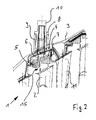
- FIG. 2 shows a schematic longitudinal section through the gap seal according to FIG. 1 with worn Honigwabendichtung 5.
- the annular gap seal is arranged radially adjustable over turbine blades 2 a low-pressure turbine 1.
- the adjusting nut 8 is fixed by a spacer 9 and screws 14 and a Verspannschraube 10 in the set position.
- a radial adjustment or readjustment of the sealing segments 4 takes place via the adjusting nut 8.
- the sealing segments 4 are guided in centering segments 7 and aligned with each other.
- the sealing segments are connected to each other in the circumferential direction via tongue and groove joints.
- the centering segments 7 are arranged offset in the circumferential direction to the sealing segments. Radially, the centering segments 7 are fixed at the front via the integral built-in clamp for the upstream guide blade and at the rear in the subsequent guide blade 11.
- the sealing segments 4 thus slide into each other when adjusting, so as to close tightly even with a smaller inner circumference.
- FIG. 3 shows a schematic cross section through a gap seal according to the invention in the new state
- FIG. 4 shows a schematic cross section according to FIG. 3 , but in the readjusted state.
- the inlet coverings ie, for example, honeycombs, omitted for reasons of clarity.
- the sealing studs 4 integrally radially outwardly projecting threaded pin 6 are shown. These threaded pins 6 have an external thread and a coaxial threaded hole. As shown on the right drawing edge, the sealing segments are fixed by means of the threaded pin 6 and the adjusting nuts 8 in its radial position and rigidly connected to the turbine housing 3.
- the adjusting nut 8 is connected via a spacer 9 and two screws 14 fixed to the housing 3. Further, a Verspannschraube 10 is screwed into the blind hole of the threaded pin 6 for backlash-free connection.
- the sealing segments 4 are latched together via tongue and groove joints 16. Furthermore, the sealing segments 4 are seated on the housing-side sealing in U-shaped centering segments 7, which are offset in the circumferential direction to the sealing segments 4.
- the centering 7 are held on the adjusting nut 8 of the sealing segments 4 and two systems 12.
- the systems 12 are designed such that the centering segments 7 remain axially freely movable and can align with the sealing segments 4.
- sealing strips 13 are provided in the rear area, which seal the space on the back of the sealing segments to the rear.
- FIG. 5 shows a detailed view of the adjusting nut 8 without threaded pin 6, without bracing screw 10 and without sealing segment 4.
- this is the connection of the adjusting nut 8 via the spacer 9 and the two screws 14 with the To recognize turbine housing 3.
- the fixation of the Zentriersegmente 7 can be seen in the circumferential direction by means of the investment pin 12, which abut against the lower extension of the adjusting nut 8.
- FIG. 6 shows a schematic representation of the assembly and disassembly of a sealing segment according to the invention.
Landscapes
- Engineering & Computer Science (AREA)
- Mechanical Engineering (AREA)
- General Engineering & Computer Science (AREA)
- Turbine Rotor Nozzle Sealing (AREA)
Applications Claiming Priority (1)
| Application Number | Priority Date | Filing Date | Title |
|---|---|---|---|
| DE200710042766 DE102007042766A1 (de) | 2007-09-07 | 2007-09-07 | Nachstellbares Dichtsegment |
Publications (2)
| Publication Number | Publication Date |
|---|---|
| EP2034133A2 true EP2034133A2 (fr) | 2009-03-11 |
| EP2034133A3 EP2034133A3 (fr) | 2011-02-23 |
Family
ID=39863073
Family Applications (1)
| Application Number | Title | Priority Date | Filing Date |
|---|---|---|---|
| EP08163839A Withdrawn EP2034133A3 (fr) | 2007-09-07 | 2008-09-08 | Segment d'étanchéité ajustable pour turbine à gaz |
Country Status (2)
| Country | Link |
|---|---|
| EP (1) | EP2034133A3 (fr) |
| DE (1) | DE102007042766A1 (fr) |
Cited By (1)
| Publication number | Priority date | Publication date | Assignee | Title |
|---|---|---|---|---|
| CN116357412A (zh) * | 2023-03-24 | 2023-06-30 | 清华大学 | 带冠涡轮叶顶间隙机械调整机构和具有其的燃气轮机 |
Citations (1)
| Publication number | Priority date | Publication date | Assignee | Title |
|---|---|---|---|---|
| US6382905B1 (en) | 2000-04-28 | 2002-05-07 | General Electric Company | Fan casing liner support |
Family Cites Families (5)
| Publication number | Priority date | Publication date | Assignee | Title |
|---|---|---|---|---|
| US2858104A (en) * | 1954-02-04 | 1958-10-28 | A V Roe Canada Ltd | Adjustable gas turbine shroud ring segments |
| GB2099515B (en) * | 1981-05-29 | 1984-09-19 | Rolls Royce | Shroud clearance control in a gas turbine engine |
| US5096375A (en) * | 1989-09-08 | 1992-03-17 | General Electric Company | Radial adjustment mechanism for blade tip clearance control apparatus |
| US5054997A (en) * | 1989-11-22 | 1991-10-08 | General Electric Company | Blade tip clearance control apparatus using bellcrank mechanism |
| DE102004037955A1 (de) * | 2004-08-05 | 2006-03-16 | Mtu Aero Engines Gmbh | Turbomaschine, insbesondere Gasturbine |
-
2007
- 2007-09-07 DE DE200710042766 patent/DE102007042766A1/de not_active Withdrawn
-
2008
- 2008-09-08 EP EP08163839A patent/EP2034133A3/fr not_active Withdrawn
Patent Citations (1)
| Publication number | Priority date | Publication date | Assignee | Title |
|---|---|---|---|---|
| US6382905B1 (en) | 2000-04-28 | 2002-05-07 | General Electric Company | Fan casing liner support |
Cited By (1)
| Publication number | Priority date | Publication date | Assignee | Title |
|---|---|---|---|---|
| CN116357412A (zh) * | 2023-03-24 | 2023-06-30 | 清华大学 | 带冠涡轮叶顶间隙机械调整机构和具有其的燃气轮机 |
Also Published As
| Publication number | Publication date |
|---|---|
| EP2034133A3 (fr) | 2011-02-23 |
| DE102007042766A1 (de) | 2009-03-12 |
Similar Documents
| Publication | Publication Date | Title |
|---|---|---|
| EP2960438B1 (fr) | Système d'aubes de guidage variables pour une turbine à gaz et turbine à gaz dotée d'un tel système | |
| DE10210866C1 (de) | Leitschaufelbefestigung in einem Strömungskanal einer Fluggasturbine | |
| EP1460237A1 (fr) | Carter pour une turbosoufflante | |
| DE1033965B (de) | Lader fuer Brennkraftmaschinen od. dgl. | |
| EP1656493A1 (fr) | Anneau de fixation segmente pour une turbine | |
| EP2918913B1 (fr) | Chambre de combustion d'une turbine à gaz | |
| EP2379846B1 (fr) | Structure de support d'aubes directrices pour turbomachine | |
| DE2914501A1 (de) | Gasturbine mit verstellbaren leitschaufeln | |
| EP2921778A1 (fr) | Chambre de combustion d'une turbine à gaz | |
| EP2342425A1 (fr) | Turbine à gaz avec plaque de fixation entre la base d'aube et le disque | |
| EP3954876B1 (fr) | Couronne directrice pour un turbocompresseur à gaz d'échappement | |
| EP2617947B1 (fr) | Turbine à gaz d'avion avec soufflante ajustable | |
| EP2054587B1 (fr) | Boîtier de turbine | |
| EP2194230A1 (fr) | Agencement d'aube directrice pour une turbomachine axiale | |
| EP2129875B1 (fr) | Turbomachine avec controle de jeu actif | |
| EP2526263B1 (fr) | Système de boîtier pour une turbomachine axiale | |
| EP2474744A1 (fr) | Canal d'écoulement annulaire pour un compresseur axial | |
| EP3176386B1 (fr) | Système de virole interne, virole interne, boîtier intermédiaire et turbomachine associés | |
| EP2808557A1 (fr) | Ensemble structurel pour une turbomachine | |
| EP1653049B1 (fr) | Couronne d'aubes directrices pour turbines à gaz et procédé pour sa modification | |
| EP2034133A2 (fr) | Segment d'étanchéité ajustable pour turbine à gaz | |
| EP3997310B1 (fr) | Segment d'aube directrice pourvu de nervure de section de support | |
| EP1960636B1 (fr) | Turbomachine | |
| EP2993305B1 (fr) | Turbine a gaz | |
| EP3921577B1 (fr) | Système de chambre de combustion à tubes et installation de turbine à gaz pourvue d'un tel système de chambre de combustion à tubes |
Legal Events
| Date | Code | Title | Description |
|---|---|---|---|
| PUAI | Public reference made under article 153(3) epc to a published international application that has entered the european phase |
Free format text: ORIGINAL CODE: 0009012 |
|
| AK | Designated contracting states |
Kind code of ref document: A2 Designated state(s): AT BE BG CH CY CZ DE DK EE ES FI FR GB GR HR HU IE IS IT LI LT LU LV MC MT NL NO PL PT RO SE SI SK TR |
|
| AX | Request for extension of the european patent |
Extension state: AL BA MK RS |
|
| PUAL | Search report despatched |
Free format text: ORIGINAL CODE: 0009013 |
|
| AK | Designated contracting states |
Kind code of ref document: A3 Designated state(s): AT BE BG CH CY CZ DE DK EE ES FI FR GB GR HR HU IE IS IT LI LT LU LV MC MT NL NO PL PT RO SE SI SK TR |
|
| AX | Request for extension of the european patent |
Extension state: AL BA MK RS |
|
| RIC1 | Information provided on ipc code assigned before grant |
Ipc: F01D 25/24 20060101ALI20110117BHEP Ipc: F01D 11/22 20060101AFI20081027BHEP |
|
| 17P | Request for examination filed |
Effective date: 20110812 |
|
| AKX | Designation fees paid |
Designated state(s): DE FR GB |
|
| STAA | Information on the status of an ep patent application or granted ep patent |
Free format text: STATUS: THE APPLICATION IS DEEMED TO BE WITHDRAWN |
|
| 18D | Application deemed to be withdrawn |
Effective date: 20140401 |