EP2034495A1 - Transformateur d'intensité, bloc de transformateur d'intensité, dispositif de réception et commutateur - Google Patents
Transformateur d'intensité, bloc de transformateur d'intensité, dispositif de réception et commutateur Download PDFInfo
- Publication number
- EP2034495A1 EP2034495A1 EP07017330A EP07017330A EP2034495A1 EP 2034495 A1 EP2034495 A1 EP 2034495A1 EP 07017330 A EP07017330 A EP 07017330A EP 07017330 A EP07017330 A EP 07017330A EP 2034495 A1 EP2034495 A1 EP 2034495A1
- Authority
- EP
- European Patent Office
- Prior art keywords
- current
- current transformer
- conductor
- plane surface
- transformers
- Prior art date
- Legal status (The legal status is an assumption and is not a legal conclusion. Google has not performed a legal analysis and makes no representation as to the accuracy of the status listed.)
- Granted
Links
- 239000004020 conductor Substances 0.000 claims abstract description 50
- 238000004519 manufacturing process Methods 0.000 description 7
- 230000000712 assembly Effects 0.000 description 5
- 238000000429 assembly Methods 0.000 description 5
- 238000009434 installation Methods 0.000 description 3
- 230000001419 dependent effect Effects 0.000 description 2
- 230000004048 modification Effects 0.000 description 2
- 238000012986 modification Methods 0.000 description 2
- 239000007858 starting material Substances 0.000 description 2
- 238000010276 construction Methods 0.000 description 1
- 230000000694 effects Effects 0.000 description 1
- 238000012423 maintenance Methods 0.000 description 1
- 239000000463 material Substances 0.000 description 1
Images



Classifications
-
- H—ELECTRICITY
- H01—ELECTRIC ELEMENTS
- H01F—MAGNETS; INDUCTANCES; TRANSFORMERS; SELECTION OF MATERIALS FOR THEIR MAGNETIC PROPERTIES
- H01F38/00—Adaptations of transformers or inductances for specific applications or functions
- H01F38/20—Instruments transformers
- H01F38/22—Instruments transformers for single phase AC
- H01F38/28—Current transformers
- H01F38/30—Constructions
Definitions
- the invention relates to a current transformer according to the preamble of claim 1.
- the invention further relates to a current transformer assembly having at least two such current transformers. It further relates to a receiving device for at least one such current transformer assembly and to a switching device with at least one such current transformer or at least one such current transformer assembly.
- Generic current transformers are well known and are often designed as a toroidal transformer. These current transformers are often planetary arranged in generally known power converter assemblies (e.g., toroidal transformer assemblies) on each of a power line extending perpendicularly through the power converter and arranged in staggered relationship within the power converter assembly. As a rule, the current transformers or current transformer assemblies are arranged in a receiving device and / or associated with an electrical switching device.
- a disadvantage of these known current transformers is a high space requirement.
- the current transformer assemblies is due to the planetary, successively staggered structure justified, also high space requirement disadvantageous, which also has a negative effect on the recording device for the current transformer or the current transformer assembly and possibly the switching device.
- the current transformer assemblies due to the arrangement of the current transformer at least two different embodiments of conductors needed, and two different connection parts with which the respective power conductors are connected, which also increases the material and labor and thus a production, installation and a Maintenance or repair more expensive.
- the invention is therefore based on the object of specifying an improved current transformer and an improved current transformer assembly. Furthermore, an improved recording device and an improved protection device should be specified.
- a current transformer with at least one inductance with a plane surface, with at least one conductor and with a perpendicular to the plane surface of the inductance arranged implementation for each one of the conductors, provided that at least a first, second and third section is comprised by the conductor.
- the first and second sections are at least partially arranged substantially parallel to the plane surface and the third section is at least partially guided through the implementation of the current transformer.
- the feedthroughs of at least two of the at least two current transformers are arranged substantially parallel to one another in a current transformer assembly having at least two current transformers of the type mentioned above or below.
- the bushings are arranged substantially on a common axis, in particular a common axis parallel to all normal axes of the inductances or a common axis which encloses an angle, in particular the same angle, with all normal axes.
- the object is achieved according to the invention by the features of claim 10 and with respect to the switching device by the features of claim 12.
- the recording device for at least one current transformer assembly of the type mentioned above or below provided that the current transformers along a common Axis are arranged.
- a reduced width, depth and / or height of the current transformer assembly is achieved.
- the object is achieved according to the invention by an assignment of at least one such current transformer or at least one such current transformer assembly for detecting currents to the switching device. Due to the smaller overall width (or overall depth, height or a combination thereof) can be used in a limited space such installation device available installation space or advantageously reduced the switching device.
- the conductor is a flat conductor. This results in an increased current carrying capacity at the same width perpendicular to the plane surface, a better deformability of the conductor and a reduction of the manufacturing effort and thus a cost reduction. Additionally or alternatively, it may be provided that the current conductor at least partially has a different cross-section, that is, e.g. at least partially a round conductor.
- a surface of the first, second or first and second portions of the flat conductor is arranged substantially parallel to the plane surface.
- first, second and third portions of the conductor are arranged substantially Z-shaped.
- a substantially right angle or a substantially obtuse angle may be included by the first and third portions, and by the second and third portions.
- the first and the second portion of the conductor are arranged on different sides of a plane perpendicular to the plane surface, which intersects the inductance substantially symmetrical.
- a contact device for producing an electrical contact of the power line comprises at least one conductor at least a portion of the second portion of the conductor, whereby a simplified construction of the current transformer and thus a cost reduction results.
- the current transformer assembly comprises at least two current transformers of the type described, wherein the bushings of at least two of the at least two current transformers are arranged substantially parallel to each other and substantially on a common axis, whereby a more compact design, a reduced width and / or a reduced height is achieved.
- the first and the second portion of the conductor are arranged substantially parallel.
- the power converter assembly may comprise three current transformers arranged on a common axis, an extension of the power converter assembly being disposed along an axis perpendicular to at least one of the plane surfaces, e.g. a width of the current transformer assembly, 45 mm does not substantially exceed.
- the respective current transformers of the current transformer assembly are substantially the same shape and the same orientation, whereby a cost in a production of the current transformer and the current transformer assembly or the receiving device is reduced. In addition to such an increase in efficiency also results in a cost reduction in the production, since, for example, one and the same production machine can be used for the production.
- At least one integrated current path for phase change is preferably provided.
- a structure of a device for phase application is simplified and minimized space requirements of the receiving device and achieved a cost reduction, for example, no additional connection devices for connecting the receiving connection or the power converter assembly with a separate device for phase application are needed.
- the receiving device comprises at least one contact point for switching a, generally known, electrical load.
- FIG. 1 shows a schematic representation of a current transformer assembly 10 according to the prior art, in which three current transformers 12a, 12b, 12c arranged planetary wheel. Two current transformers 12a, 12c are located in one plane. The third current transformer 12b is located substantially outside this plane.
- Each current transformer 12a, 12b, 12c in each case comprises an inductance 14a, 14b, 14c with a feedthrough 16a, 16b, 16c arranged perpendicular to a plane surface of the inductance 14a, 14b, 14c for a respective current conductor 18a, 18b, 18c.
- one of the current conductors 18a, 18b, 18c is guided vertically through the corresponding bushing 16a, 16b, 16c, and a contact device 20a, 20b, 20c contacts one of the current conductors 18a, 18b, 18c in each case.
- FIG. 2 shows a schematic representation of a recording device 22 with current transformer assembly 10 (in FIG. 1 ) according to the prior art with the contact devices 20a, 20b, 20c of the current conductors 18a, 18b, 18c and one of the current transformers 12a, 12b, 12c (in FIG. 1
- the receiving device 22 has due to the arrangement of in FIG. 1 shown current transformers 12a, 12b, 12c a large height, width and depth.
- FIG. 3 shows a schematic plan view of an embodiment of a current transformer assembly 10 according to the invention with three current transformers 12a, 12b, 12c, with substantially the same shape and the same orientation, in a receiving device 22.
- the current transformers 12a, 12b, 12c are arranged such that the inductances 14a, 14b, 14c lie on a common axis running perpendicular to the plane surfaces.
- Each current transformer 12a, 12b, 12c comprises an inductance 14a, 14b, 14c with a plane perpendicular to which the leadthrough 16a, 16b, 16c for one of the current conductors 18a, 18b, 18c, which are formed as a flat conductor, is arranged.
- the current conductors 18a, 18b, 18c each comprise a first portion 24a, 24b, 24c and a second portion 26a, 26b, 26c, which are arranged parallel to the plane surface of the inductance 14a, 14b, 14c. Additionally or alternatively, the second portion 26a, 26b, 26c may comprise the contact device 20a, 20b, 20c, and further the contact devices 20a, 20b, 20c may also be of substantially the same shape and orientation.
- a third section 28a, 28b, 28c located between the first and second sections 24a-c, 26a-c is from a first side of the planar surface to a second side of the planar surface through the passage 16a, 16b, 16c of the current transformer 12a, 12b , 12c led.
- FIG. 4 shows a schematic perspective view of the current transformer assembly 10 from FIG. 3 in disassembled condition, all for FIG. 3 having described elements. However, here is an arrangement of the third portion 28a-c which is in FIG. 3 due to the inductances 14a, 14b, 14c is partially not visible, clearly visible.
- the first, second and third sections 24a-c, 26a-c, 28a-c of the current conductors 18a, 18b, 18c are arranged in a substantially Z-shaped manner.
- FIG. 5 shows a schematic, perspective view of an alternative embodiment of a current transformer assembly 10 according to the invention, which in its basic features of in FIG. 3 represented corresponds.
- the three current transformers 12a, 12b, 12c of the current transformer assembly 10 are arranged such that the inductances 14a, 14b, 14c are arranged on a common axis designated by X. are, which with the parallel plane surfaces an angle, here an angle different from 90 °, includes.
- the connecting device 20a, 20b, 20c is mechanically and electrically conductively connected to the current conductor 18a, 18b, 18c by means of a recess 30a, 30b, 30c corresponding to a cross section of the current conductor 18a, 18b, 18c.
- a conductor contact 31a, 31b, 31c may be provided, with which the first portion 24a, 24b, 24c is electrically conductively connected and which may also be an integral part of the receiving device 22.
- FIG. 6 shows a further schematic perspective view of the current transformer assembly 10 from FIG. 5 ,
- a contact point 31d, 31e, 31f is integrated into the receiving device 22.
- the second portion 26a, 26b, 26c of the current conductor 18a, 18b, 18c is in electrical contact with the contact point 31d, 31e, 31f.
- the current conductor 18a, 18b, 18c can be firmly connected to the respective contact point 31d, 31e, 31f, eg by means of a soldered connection, screw connection or the like, or the contact point 31d, 31e, 31f can be encompassed by the current conductor 18a, 18b, 18c.
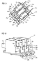
- FIG. 7 shows a schematic, perspective view of an embodiment of a receiving device 22 according to the invention for a current transformer assembly 10 to a phase change, which substantially the in FIG. 3 represented current transformer assembly 10 corresponds.
- the receiving device 22 is thereby formed for receiving in each case one, with one of the current conductors 18a, 18b, 18c corresponding first, second and third current path 32a, 32b, 32c.
- the current paths 32c, 32b, 32a include furthermore, in each case a third contact region 38c, 38b, 38a.
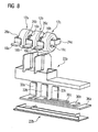
- FIG. 8 schematically shows the recording device FIG. 7 from another perspective and in disassembled state.
- a first part 22a of the receiving device 22 is designed to receive the inductors 14a, 14b, 14c and the current conductors 18a, 18b, 18c and to receive the current paths 32c, 32b, 32a corresponding to the current conductors 18a, 18b, 18c.
- the third contact areas 38c-a are accessible; for phase-shifting, the first current path 32a is passed around the second current path 32b and this in turn is led around the third current path 32c.
- a current transformer 12a, 12b, 12c with at least one inductance 14a, 14b, 14c with a plane surface, at least one current conductor 18a, 18b, 18c and with a perpendicular to the plane surface of the inductance 14a, 14b, 14c arranged bushing 16a, 16b, 16c for each one of the current conductors 18a, 18b, 18c, wherein of the current conductor 18a, 18b, 18c at least a first, second and third portion 24a, 24b, 24c, 26a, 26c, 26c, 28a, 28b, 28c is included, wherein the first and second portions 24a, 24b, 24c, 26a, 26b, 26c are at least partially disposed substantially parallel to the plane surface and wherein the third portion 28a, 28b, 28c at least partially through the passage 16a, 16b, 16c of the current transformer 12a, 12b, 12c is feasible, a current transformer assembly 10 with at least two such current transformers 12a
Landscapes
- Engineering & Computer Science (AREA)
- Power Engineering (AREA)
- Transformers For Measuring Instruments (AREA)
Priority Applications (1)
| Application Number | Priority Date | Filing Date | Title |
|---|---|---|---|
| EP20070017330 EP2034495B1 (fr) | 2007-09-04 | 2007-09-04 | Bloc de transformateur d'intensité, dispositif de réception et commutateur |
Applications Claiming Priority (1)
| Application Number | Priority Date | Filing Date | Title |
|---|---|---|---|
| EP20070017330 EP2034495B1 (fr) | 2007-09-04 | 2007-09-04 | Bloc de transformateur d'intensité, dispositif de réception et commutateur |
Publications (2)
| Publication Number | Publication Date |
|---|---|
| EP2034495A1 true EP2034495A1 (fr) | 2009-03-11 |
| EP2034495B1 EP2034495B1 (fr) | 2015-03-18 |
Family
ID=38917383
Family Applications (1)
| Application Number | Title | Priority Date | Filing Date |
|---|---|---|---|
| EP20070017330 Not-in-force EP2034495B1 (fr) | 2007-09-04 | 2007-09-04 | Bloc de transformateur d'intensité, dispositif de réception et commutateur |
Country Status (1)
| Country | Link |
|---|---|
| EP (1) | EP2034495B1 (fr) |
Citations (6)
| Publication number | Priority date | Publication date | Assignee | Title |
|---|---|---|---|---|
| DE1133817B (de) | 1961-02-06 | 1962-07-26 | Licentia Gmbh | Stromwandler mit aus zwei Stromschienen bestehender Primaerwicklung |
| GB905425A (en) * | 1958-09-22 | 1962-09-05 | Gardy Particip App | Improvements in and relating to polyphase current transformers |
| JPS60257111A (ja) | 1984-06-01 | 1985-12-18 | Hitachi Ltd | 貫通型変流器の一次導体支持装置 |
| EP1109192A2 (fr) | 1999-12-17 | 2001-06-20 | M. Schneider, Schaltgerätebau und Elektroinstallationen Gesellschaft m.b.H. | Conducteur pour un transformateur de courant dans un dispositif à fusible basse tension haute puissance ou de coupure en charge |
| DE10002800A1 (de) | 2000-01-24 | 2001-08-09 | Woehner Gmbh & Co Kg | NH-Sicherungsleiste |
| US20060066425A1 (en) | 2004-09-29 | 2006-03-30 | Gruner Klaus A | Multi-phase electromagnetic relay assembly and motor assembly |
-
2007
- 2007-09-04 EP EP20070017330 patent/EP2034495B1/fr not_active Not-in-force
Patent Citations (6)
| Publication number | Priority date | Publication date | Assignee | Title |
|---|---|---|---|---|
| GB905425A (en) * | 1958-09-22 | 1962-09-05 | Gardy Particip App | Improvements in and relating to polyphase current transformers |
| DE1133817B (de) | 1961-02-06 | 1962-07-26 | Licentia Gmbh | Stromwandler mit aus zwei Stromschienen bestehender Primaerwicklung |
| JPS60257111A (ja) | 1984-06-01 | 1985-12-18 | Hitachi Ltd | 貫通型変流器の一次導体支持装置 |
| EP1109192A2 (fr) | 1999-12-17 | 2001-06-20 | M. Schneider, Schaltgerätebau und Elektroinstallationen Gesellschaft m.b.H. | Conducteur pour un transformateur de courant dans un dispositif à fusible basse tension haute puissance ou de coupure en charge |
| DE10002800A1 (de) | 2000-01-24 | 2001-08-09 | Woehner Gmbh & Co Kg | NH-Sicherungsleiste |
| US20060066425A1 (en) | 2004-09-29 | 2006-03-30 | Gruner Klaus A | Multi-phase electromagnetic relay assembly and motor assembly |
Also Published As
| Publication number | Publication date |
|---|---|
| EP2034495B1 (fr) | 2015-03-18 |
Similar Documents
| Publication | Publication Date | Title |
|---|---|---|
| DE4222068C1 (fr) | ||
| EP1618580B1 (fr) | Appareil de commutation electromecanique | |
| DE102015107605B4 (de) | Induktives Bauelement für Leiterplattenmontage und Wechselrichter mit einem leiterplattenmontierten induktiven Bauelement | |
| EP3642858B1 (fr) | Condensateur de circuit intermédiaire | |
| EP3906609B1 (fr) | Machine électrique | |
| WO1993018528A1 (fr) | Bobine pour un transformeur haute tension | |
| EP2630709B1 (fr) | Procédé pour raccorder au moins deux câbles électriques et dispositif de raccordement, ensemble prêt-à-monter, moteur électrique et véhicule correspondants | |
| DE102006005046A1 (de) | Elektrische Maschine mit ungleichmäßigen Polzähnen | |
| EP1774545B1 (fr) | Support destine a un composant electrique | |
| DE69510317T2 (de) | Metallgekapselte gasisolierte Schaltvorrichtung | |
| DE4008417C2 (de) | Vorrichtung zur Verbindung der elektrischen Anschlüsse von Kondensatoren | |
| EP0221839A2 (fr) | Interrupteur de puissance comportant un boîtier isolant à ouverture frontale et une plaquette de circuit | |
| DE2850657A1 (de) | Drosselspule | |
| EP2034495B1 (fr) | Bloc de transformateur d'intensité, dispositif de réception et commutateur | |
| EP2428303A1 (fr) | Transformateur pour une pince de soudage | |
| EP0174385B1 (fr) | Dispositif de support pour conducteurs électriques | |
| DE29615563U1 (de) | Bewegbare Schaltkontaktanordnung mit Kontaktkraftfedern | |
| DE10061564A1 (de) | Anschlußeinheit für mehrpoligen Schalter | |
| EP3756201B1 (fr) | Transformateur d'alimentation basse tension pour applications de protection basse tension | |
| DE102004008961A1 (de) | Spulenkörper für geschlossenen magnetischen Kern und daraus hergestellte Entstördrossel | |
| DE2816356C2 (de) | Primärseitig umschaltbarer Stromwandler | |
| WO2005043567A1 (fr) | Transformateur rotatif | |
| EP1282142B1 (fr) | Système d'enroulement électrique | |
| DE102012215862B4 (de) | Oberflächenmontierbare Drossel | |
| EP2362510A2 (fr) | Agencement de fixation de jeux de barres |
Legal Events
| Date | Code | Title | Description |
|---|---|---|---|
| PUAI | Public reference made under article 153(3) epc to a published international application that has entered the european phase |
Free format text: ORIGINAL CODE: 0009012 |
|
| AK | Designated contracting states |
Kind code of ref document: A1 Designated state(s): AT BE BG CH CY CZ DE DK EE ES FI FR GB GR HU IE IS IT LI LT LU LV MC MT NL PL PT RO SE SI SK TR |
|
| AX | Request for extension of the european patent |
Extension state: AL BA HR MK RS |
|
| 17P | Request for examination filed |
Effective date: 20090608 |
|
| AKX | Designation fees paid |
Designated state(s): AT BE BG CH CY CZ DE DK EE ES FI FR GB GR HU IE IS IT LI LT LU LV MC MT NL PL PT RO SE SI SK TR |
|
| 17Q | First examination report despatched |
Effective date: 20120504 |
|
| RAP1 | Party data changed (applicant data changed or rights of an application transferred) |
Owner name: SIEMENS AKTIENGESELLSCHAFT |
|
| GRAP | Despatch of communication of intention to grant a patent |
Free format text: ORIGINAL CODE: EPIDOSNIGR1 |
|
| INTG | Intention to grant announced |
Effective date: 20141020 |
|
| GRAS | Grant fee paid |
Free format text: ORIGINAL CODE: EPIDOSNIGR3 |
|
| GRAA | (expected) grant |
Free format text: ORIGINAL CODE: 0009210 |
|
| AK | Designated contracting states |
Kind code of ref document: B1 Designated state(s): AT BE BG CH CY CZ DE DK EE ES FI FR GB GR HU IE IS IT LI LT LU LV MC MT NL PL PT RO SE SI SK TR |
|
| REG | Reference to a national code |
Ref country code: GB Ref legal event code: FG4D Free format text: NOT ENGLISH |
|
| REG | Reference to a national code |
Ref country code: CH Ref legal event code: EP |
|
| REG | Reference to a national code |
Ref country code: IE Ref legal event code: FG4D Free format text: LANGUAGE OF EP DOCUMENT: GERMAN |
|
| REG | Reference to a national code |
Ref country code: AT Ref legal event code: REF Ref document number: 717027 Country of ref document: AT Kind code of ref document: T Effective date: 20150415 |
|
| REG | Reference to a national code |
Ref country code: DE Ref legal event code: R096 Ref document number: 502007013795 Country of ref document: DE Effective date: 20150430 |
|
| REG | Reference to a national code |
Ref country code: NL Ref legal event code: VDEP Effective date: 20150318 |
|
| REG | Reference to a national code |
Ref country code: NL Ref legal event code: VDEP Effective date: 20150318 |
|
| PG25 | Lapsed in a contracting state [announced via postgrant information from national office to epo] |
Ref country code: LT Free format text: LAPSE BECAUSE OF FAILURE TO SUBMIT A TRANSLATION OF THE DESCRIPTION OR TO PAY THE FEE WITHIN THE PRESCRIBED TIME-LIMIT Effective date: 20150318 Ref country code: FI Free format text: LAPSE BECAUSE OF FAILURE TO SUBMIT A TRANSLATION OF THE DESCRIPTION OR TO PAY THE FEE WITHIN THE PRESCRIBED TIME-LIMIT Effective date: 20150318 Ref country code: SE Free format text: LAPSE BECAUSE OF FAILURE TO SUBMIT A TRANSLATION OF THE DESCRIPTION OR TO PAY THE FEE WITHIN THE PRESCRIBED TIME-LIMIT Effective date: 20150318 |
|
| REG | Reference to a national code |
Ref country code: LT Ref legal event code: MG4D |
|
| PG25 | Lapsed in a contracting state [announced via postgrant information from national office to epo] |
Ref country code: LV Free format text: LAPSE BECAUSE OF FAILURE TO SUBMIT A TRANSLATION OF THE DESCRIPTION OR TO PAY THE FEE WITHIN THE PRESCRIBED TIME-LIMIT Effective date: 20150318 Ref country code: GR Free format text: LAPSE BECAUSE OF FAILURE TO SUBMIT A TRANSLATION OF THE DESCRIPTION OR TO PAY THE FEE WITHIN THE PRESCRIBED TIME-LIMIT Effective date: 20150619 |
|
| PG25 | Lapsed in a contracting state [announced via postgrant information from national office to epo] |
Ref country code: NL Free format text: LAPSE BECAUSE OF FAILURE TO SUBMIT A TRANSLATION OF THE DESCRIPTION OR TO PAY THE FEE WITHIN THE PRESCRIBED TIME-LIMIT Effective date: 20150318 |
|
| PG25 | Lapsed in a contracting state [announced via postgrant information from national office to epo] |
Ref country code: PT Free format text: LAPSE BECAUSE OF FAILURE TO SUBMIT A TRANSLATION OF THE DESCRIPTION OR TO PAY THE FEE WITHIN THE PRESCRIBED TIME-LIMIT Effective date: 20150720 Ref country code: SK Free format text: LAPSE BECAUSE OF FAILURE TO SUBMIT A TRANSLATION OF THE DESCRIPTION OR TO PAY THE FEE WITHIN THE PRESCRIBED TIME-LIMIT Effective date: 20150318 Ref country code: RO Free format text: LAPSE BECAUSE OF FAILURE TO SUBMIT A TRANSLATION OF THE DESCRIPTION OR TO PAY THE FEE WITHIN THE PRESCRIBED TIME-LIMIT Effective date: 20150318 Ref country code: EE Free format text: LAPSE BECAUSE OF FAILURE TO SUBMIT A TRANSLATION OF THE DESCRIPTION OR TO PAY THE FEE WITHIN THE PRESCRIBED TIME-LIMIT Effective date: 20150318 Ref country code: ES Free format text: LAPSE BECAUSE OF FAILURE TO SUBMIT A TRANSLATION OF THE DESCRIPTION OR TO PAY THE FEE WITHIN THE PRESCRIBED TIME-LIMIT Effective date: 20150318 Ref country code: CZ Free format text: LAPSE BECAUSE OF FAILURE TO SUBMIT A TRANSLATION OF THE DESCRIPTION OR TO PAY THE FEE WITHIN THE PRESCRIBED TIME-LIMIT Effective date: 20150318 |
|
| PG25 | Lapsed in a contracting state [announced via postgrant information from national office to epo] |
Ref country code: IS Free format text: LAPSE BECAUSE OF FAILURE TO SUBMIT A TRANSLATION OF THE DESCRIPTION OR TO PAY THE FEE WITHIN THE PRESCRIBED TIME-LIMIT Effective date: 20150718 Ref country code: PL Free format text: LAPSE BECAUSE OF FAILURE TO SUBMIT A TRANSLATION OF THE DESCRIPTION OR TO PAY THE FEE WITHIN THE PRESCRIBED TIME-LIMIT Effective date: 20150318 |
|
| REG | Reference to a national code |
Ref country code: DE Ref legal event code: R097 Ref document number: 502007013795 Country of ref document: DE |
|
| PLBE | No opposition filed within time limit |
Free format text: ORIGINAL CODE: 0009261 |
|
| STAA | Information on the status of an ep patent application or granted ep patent |
Free format text: STATUS: NO OPPOSITION FILED WITHIN TIME LIMIT |
|
| PG25 | Lapsed in a contracting state [announced via postgrant information from national office to epo] |
Ref country code: DK Free format text: LAPSE BECAUSE OF FAILURE TO SUBMIT A TRANSLATION OF THE DESCRIPTION OR TO PAY THE FEE WITHIN THE PRESCRIBED TIME-LIMIT Effective date: 20150318 |
|
| 26N | No opposition filed |
Effective date: 20151221 |
|
| PG25 | Lapsed in a contracting state [announced via postgrant information from national office to epo] |
Ref country code: SI Free format text: LAPSE BECAUSE OF FAILURE TO SUBMIT A TRANSLATION OF THE DESCRIPTION OR TO PAY THE FEE WITHIN THE PRESCRIBED TIME-LIMIT Effective date: 20150318 |
|
| PG25 | Lapsed in a contracting state [announced via postgrant information from national office to epo] |
Ref country code: LU Free format text: LAPSE BECAUSE OF FAILURE TO SUBMIT A TRANSLATION OF THE DESCRIPTION OR TO PAY THE FEE WITHIN THE PRESCRIBED TIME-LIMIT Effective date: 20150904 Ref country code: MC Free format text: LAPSE BECAUSE OF FAILURE TO SUBMIT A TRANSLATION OF THE DESCRIPTION OR TO PAY THE FEE WITHIN THE PRESCRIBED TIME-LIMIT Effective date: 20150318 |
|
| REG | Reference to a national code |
Ref country code: CH Ref legal event code: PL |
|
| GBPC | Gb: european patent ceased through non-payment of renewal fee |
Effective date: 20150904 |
|
| REG | Reference to a national code |
Ref country code: IE Ref legal event code: MM4A |
|
| PG25 | Lapsed in a contracting state [announced via postgrant information from national office to epo] |
Ref country code: IE Free format text: LAPSE BECAUSE OF NON-PAYMENT OF DUE FEES Effective date: 20150904 Ref country code: CH Free format text: LAPSE BECAUSE OF NON-PAYMENT OF DUE FEES Effective date: 20150930 Ref country code: LI Free format text: LAPSE BECAUSE OF NON-PAYMENT OF DUE FEES Effective date: 20150930 Ref country code: GB Free format text: LAPSE BECAUSE OF NON-PAYMENT OF DUE FEES Effective date: 20150904 |
|
| REG | Reference to a national code |
Ref country code: FR Ref legal event code: PLFP Year of fee payment: 10 |
|
| REG | Reference to a national code |
Ref country code: AT Ref legal event code: MM01 Ref document number: 717027 Country of ref document: AT Kind code of ref document: T Effective date: 20150904 |
|
| PG25 | Lapsed in a contracting state [announced via postgrant information from national office to epo] |
Ref country code: AT Free format text: LAPSE BECAUSE OF NON-PAYMENT OF DUE FEES Effective date: 20150904 |
|
| PG25 | Lapsed in a contracting state [announced via postgrant information from national office to epo] |
Ref country code: MT Free format text: LAPSE BECAUSE OF FAILURE TO SUBMIT A TRANSLATION OF THE DESCRIPTION OR TO PAY THE FEE WITHIN THE PRESCRIBED TIME-LIMIT Effective date: 20150318 |
|
| PG25 | Lapsed in a contracting state [announced via postgrant information from national office to epo] |
Ref country code: BG Free format text: LAPSE BECAUSE OF FAILURE TO SUBMIT A TRANSLATION OF THE DESCRIPTION OR TO PAY THE FEE WITHIN THE PRESCRIBED TIME-LIMIT Effective date: 20150318 Ref country code: HU Free format text: LAPSE BECAUSE OF FAILURE TO SUBMIT A TRANSLATION OF THE DESCRIPTION OR TO PAY THE FEE WITHIN THE PRESCRIBED TIME-LIMIT; INVALID AB INITIO Effective date: 20070904 |
|
| PG25 | Lapsed in a contracting state [announced via postgrant information from national office to epo] |
Ref country code: CY Free format text: LAPSE BECAUSE OF FAILURE TO SUBMIT A TRANSLATION OF THE DESCRIPTION OR TO PAY THE FEE WITHIN THE PRESCRIBED TIME-LIMIT Effective date: 20150318 |
|
| PG25 | Lapsed in a contracting state [announced via postgrant information from national office to epo] |
Ref country code: BE Free format text: LAPSE BECAUSE OF NON-PAYMENT OF DUE FEES Effective date: 20150930 |
|
| PG25 | Lapsed in a contracting state [announced via postgrant information from national office to epo] |
Ref country code: TR Free format text: LAPSE BECAUSE OF FAILURE TO SUBMIT A TRANSLATION OF THE DESCRIPTION OR TO PAY THE FEE WITHIN THE PRESCRIBED TIME-LIMIT Effective date: 20150318 |
|
| REG | Reference to a national code |
Ref country code: FR Ref legal event code: PLFP Year of fee payment: 11 |
|
| REG | Reference to a national code |
Ref country code: FR Ref legal event code: PLFP Year of fee payment: 12 |
|
| PGFP | Annual fee paid to national office [announced via postgrant information from national office to epo] |
Ref country code: FR Payment date: 20200921 Year of fee payment: 14 |
|
| PGFP | Annual fee paid to national office [announced via postgrant information from national office to epo] |
Ref country code: IT Payment date: 20200924 Year of fee payment: 14 Ref country code: DE Payment date: 20201118 Year of fee payment: 14 |
|
| REG | Reference to a national code |
Ref country code: DE Ref legal event code: R119 Ref document number: 502007013795 Country of ref document: DE |
|
| PG25 | Lapsed in a contracting state [announced via postgrant information from national office to epo] |
Ref country code: FR Free format text: LAPSE BECAUSE OF NON-PAYMENT OF DUE FEES Effective date: 20210930 Ref country code: DE Free format text: LAPSE BECAUSE OF NON-PAYMENT OF DUE FEES Effective date: 20220401 |
|
| PG25 | Lapsed in a contracting state [announced via postgrant information from national office to epo] |
Ref country code: IT Free format text: LAPSE BECAUSE OF NON-PAYMENT OF DUE FEES Effective date: 20210904 |