EP2034573A2 - Elément de sécurité, dispositif et procédé de sécurisation de lignes aériennes - Google Patents
Elément de sécurité, dispositif et procédé de sécurisation de lignes aériennes Download PDFInfo
- Publication number
- EP2034573A2 EP2034573A2 EP08015348A EP08015348A EP2034573A2 EP 2034573 A2 EP2034573 A2 EP 2034573A2 EP 08015348 A EP08015348 A EP 08015348A EP 08015348 A EP08015348 A EP 08015348A EP 2034573 A2 EP2034573 A2 EP 2034573A2
- Authority
- EP
- European Patent Office
- Prior art keywords
- securing element
- guide
- roller
- tether
- securing
- Prior art date
- Legal status (The legal status is an assumption and is not a legal conclusion. Google has not performed a legal analysis and makes no representation as to the accuracy of the status listed.)
- Withdrawn
Links
Images



Classifications
-
- H—ELECTRICITY
- H02—GENERATION; CONVERSION OR DISTRIBUTION OF ELECTRIC POWER
- H02G—INSTALLATION OF ELECTRIC CABLES OR LINES, OR OF COMBINED OPTICAL AND ELECTRIC CABLES OR LINES
- H02G1/00—Methods or apparatus specially adapted for installing, maintaining, repairing or dismantling electric cables or lines
- H02G1/02—Methods or apparatus specially adapted for installing, maintaining, repairing or dismantling electric cables or lines for overhead lines or cables
- H02G1/04—Methods or apparatus specially adapted for installing, maintaining, repairing or dismantling electric cables or lines for overhead lines or cables for mounting or stretching
Definitions
- the invention relates to a fuse element, a device and a method for securing overhead lines, such as overhead power lines, during assembly, disassembly and / or during the execution of maintenance measures, in particular for the protection of crossover objects, with a comparatively complicated framework position and / or a shutdown affected overhead power transmission line to protect underlying, the respective overhead line crossing objects can be omitted.
- overhead lines such as overhead power lines
- An overhead line is an electrical line in which non-insulated conductor cables are used as conductors.
- a predetermined ground clearance is to be observed for overhead lines, which depends on the particular voltage of the overhead line, so at voltages up to 1 kV, a minimum ground clearance of 4 m must be observed.
- a power transmission line of, for example, 110 kV and more, a correspondingly greater ground clearance of approx. 18 m must be maintained.
- maintenance and / or expansion in particular also the transmission capacity and the associated communication paths of power transmission lines are for protection against crossing objects, ie located below the respective overhead line objects, such as underlying paths, roads, rivers, forests, railways, u communication links
- the affected overhead power lines usually turn off or shut down and / or appropriate protective scaffolding
- To set up or build which is connected to the respective network operator with considerable effort in particular also in terms of preparation time and costs, since he can not meet his network and thus also his mission even during the performance of maintenance.
- a shutdown of the respective supply network over a longer period is not possible.
- the invention is based on the object an efficient way to secure high voltage overhead lines to protect underlying intersection objects, which allows assembly / disassembly of overhead lines and the related implementation of maintenance measures with the least possible effort, especially while avoiding a shutdown of the respective supply network ,
- a securing element having the features of claim 1.
- a device for securing overhead lines, in particular high-voltage overhead lines, and an arrangement with a plurality of such devices and a corresponding method and advantageous refinements and developments of the invention are specified in further claims and the following description.
- the securing element according to the invention comprises a holding frame with at least one roller for receiving at least one overhead line, wherein at least a first holding means is provided, through which the securing element with at least one guide cable is connectable, and wherein at least a second holding means is provided, through which the securing element with at least a tether is connectable.
- the support frame can be V-shaped or Y-shaped or U-shaped and / or at least two legs between which arranged at least one roller and / or rotatable, for example, on / in a bearing or a bearing pin, supported or stored is.
- the securing element can be arranged by means of the at least one guide cable between two sub-conductors, in particular two live sub-conductors, at least one transmission system of a power transmission line, preferably one or two guide cables are used.
- the securing element can be fixed and / or positioned by means of the at least one tether relative to at least one fixed and / or anchor point, it being possible to determine via the tether length with which tensioning force or tensile force the securing element is acted upon and / or at what distance from the respective one Anchor or fixed point is held.
- the first holding means comprises a plurality of rotatably mounted guide rollers, in particular three or four guide rollers whose axes of rotation or bearings aligned perpendicular to the axis of rotation of the at least one roller and / or arranged or formed.
- the running surface of the respective guide roller may be concave or conical, so that a corresponding guide cable is well received and held, or the respective securing element can be safely carried and guided by the guide cable.
- the dimensions of the guide rollers of the at least one first holding means in particular circumference and / or diameter and / or tread, thereby adapted to the thickness or the diameter of the at least one to be used supporting cable or the respectively used guide cable, so that a Optimal seat of the fuse element on and given a secure connection with the supporting cable or guide rope or can be reached
- the respective securing element by means of the guide rollers of the at least one first holding means on the at least one guide cable can be placed and / or suspended.
- At least one closable securing bow and / or bolt for one or more guide rollers can be provided for safety-related reasons, by which in the closed state of the bracket / bolt, especially in sudden load peaks, such as sudden load absorption in the form of an overhead line, and / or in the case of cable vibrations and / or in comparatively tense winds, a spring-down of the securing element or a guide roller of at least one guide cable and / or a jumping off of at least one tether from the respective roller can be prevented and / or inhibited.
- the at least one first holding means to have at least one fastening eyelet and / or loop and / or hook on which at least one guide cable, in particular one guide cable, can be attached and / or fastened and / or by which at least one guide cable is feasible, for example, as another safety-related measure.
- the running surface of the at least one roller of the securing element may also be concave or conical and / or adapted to the diameter or thickness of the particular to be secured overhead line so that it can be well guided and / or taken in case of need.
- the second holding means has at least one, preferably rotatably mounted, guide roller whose axis of rotation is aligned and / or formed perpendicular to the axis of rotation of the at least one roller.
- the securing element can be further developed such that at least one closable securing bracket and / or bolt is provided for at least one guiding roller of the at least one second holding means, which, in particular in the case of suddenly occurring load peaks and / or cable vibrations, for example when stronger winds occur, a dropping down of at least prevents and / or inhibits a tether.
- the running surface of the at least one guide roller of the at least one second holding means can be concave or conical and / or adapted to the diameter of the at least one tether used.
- guide rollers in the region of the first and / or second holding means allows by applying tensile forces by means of at least one tether on the fuse element easy positioning and / or centering of the fuse element, for example, between two sub-conductors, in particular two live sub-conductors, at least one transmission system of a power transmission line ,
- the at least one first and / or one second holding means can also be designed such that at least one rail is provided for guiding and receiving the guide cable and / or the tether.
- This can also have a hollow profile, which is in particular concave auslagbar.
- at least one clamp in particular a screw clamp, is provided for fastening the at least one guide cable and / or the at least one tether to the safety element.
- the at least one second holding means has at least one fastening eyelet and / or loop and / or hook, through which at least one tether can be guided or to which one end of the respective tether can be attached and / or fastened.
- the at least one roller and / or at least one guide roller of the first holding means and / or at least one guide roller of the second holding means of electrically insulating material, in particular a plastic or a ceramic formed.
- a device for securing overhead lines in particular high-voltage overhead lines, which comprises at least one fuse element of the aforementioned type and at least two electrically insulating ropes, wherein at least one insulating rope as a guide cable for guiding is provided of the securing element and at least one insulating rope is provided as a tether for fixing and / or positioning of the securing element against at least one fixed or anchor point.
- the at least one guide cable is arranged between two partial conductors, in particular two voltage-carrying partial conductors, at least one transmission system of a high-voltage overhead line. Where the device is basically used for other applications.
- An attachment of the respective guide cable to the sub-conductor can be effected via a can be arranged at a free end of the respective guide cable terminal, which may be in particular a screw terminal at the terminal.
- the securing element by means of at least one tether against the at least one, in particular located on the ground, fixed or anchor point and by means of at least one guide cable against the at least two sub-conductors can be clamped.
- the length of the at least one guide cable and / or the at least one tether is adapted and / or dimensioned such that the permissible distance or required minimum distance between the at least one overhead line receiving fuse element and at least one crossing object and / or the respective Overhead line and at least one crossing object, especially the ground, is respected.
- the securing element is movable, in particular displaceable on or on the guide cable can be arranged.
- the distance to be maintained can be dimensioned as a function of the respective voltage value of the respective overhead line.
- the at least one insulating cable provided as a guide cable and / or the at least one insulating cable provided as a tether is designed in such a way that any leakage currents occurring do not exceed 500 ⁇ A each.
- the at least one first holding means and the at least one guide cable are aligned and / or arranged with respect to each other such that a dissolved overhead line can be guided or guided onto and / or along the respective guide cable onto the running surface of the roller.
- one or more of the aforementioned devices along an overhead line to each other can be arranged spaced apart to secure an overhead line, in particular, the distance between two devices is about 5m.
- the object is further achieved by a method for securing overhead lines, in particular high-voltage overhead lines, using at least one of the aforementioned devices, wherein at least one securing element by means of at least one designed as a guide rope, electrically insulating cable between two sub-conductors, in particular two live sub-conductors, at least a transmission system of a power transmission line is arranged, as well as the at least one fuse element is fixed and / or positioned by means of at least one designed as a tether electrically insulated cable opposite at least one crossing object and / or against at least one fixed or anchor point.
- a further development according to the method provides that a guide cable is used which is detachably connected to the two sub-conductors at its two free ends, preferably via clamps, or fastened thereto.
- the securing element is movably arranged on or on the at least one guide cable, whereby, even after mounting the at least one guide cable between two sub-conductors, a simple alignment and or positioning, in particular by means of at least one tether, is made possible.
- the attachment of the at least one guide cable to the sub-conductors, in particular the live sub-conductors is effected by driving the sub-conductors with suitable trunk vehicles and / or the use of suitable highly insulating aerial work platforms.
- the respective securing element can be braced in such a way that at least one crossing element and / or against at least one fixed or anchor point in such a way that the at least one guide cable, the securing element and the at least one tether a Have X and / or Y-form or structure.
- the respective overhead line gently and without damage to the at least one roller of the respective fuse element.
- this process is largely automatic.
- the present invention accordingly allows, also due to the simple and fast mounting option, an efficient backup of power transmission lines to perform at relatively low cost to protect underlying intersection objects, as complex scaffolding work can be avoided and in particular a shutdown of the respective supply network can be omitted.
- FIG. 1 is a device for securing overhead lines, in particular high-voltage overhead lines, for the protection of underlying intersection objects, such as roads, streets, buildings, railways, rivers or telephone lines shown.
- This device comprises a securing element 2 with a holding frame 4 with a roller 6 for receiving at least one to be mounted or disassembled overhead line.
- the holding frame 4 has substantially two legs 8, wherein each leg 8 has at its upper end in each case a recess or eyelet 9 for fixing in each case a guide cable 12, which form the first holding means 10, and at its lower end in each case a recess or Eyelet 11 for attachment of a respective tether 16, which form the second holding means 14 has.
- each guide cable 12 is detachably connected via respective terminals 18, each with a sub-line 20 of a transmission system of a power transmission line.
- the two secured to the securing element tethers 16 are clamped crosswise, each with a fixed or anchor point on the ground, wherein the fixed and / or anchor points 24 are flanking on opposite sides, the respective intersection object-
- the respective fixed and / or anchor point can be formed by an appropriate fastener such as ground anchor, Einschlagpfosten, concrete foundation with mounting lugs or hooks or the like more.
- the crossed tethers 16 a particularly stable orientation of the securing element 2 is achieved, with an attachment with non-crossed tethers 16 is basically possible. Due to the tensile force acted upon by the tethers 16 on the securing element 2 and the guide cables 12, the guide cables 12 form a kind of two-dimensional funnel or cone, whereby a dissolved overhead line, guided along the guide cables directly to the roller 6 or on their tread and / or directed becomes.
- the acting tensile forces, forces in the respective ropes, as well as the distance from the fuse element 2 to the respective intersection object can be regulated and / or adjusted.
- the position of the securing element 2 relative to the sub-conductors 20 and / or the respective crossing object can be determined via the respective length of the individual guide cables 12, wherein a horizontally centric (central) arrangement between the sub-conductors 20 due to the more favorable or more balanced load distribution is preferable.
- the guide cables 12 and the tethers 16 are formed from electrically insulating ropes, so that only working currents of not more than 500 ⁇ A can be formed.
- a plurality of such devices in order to protect extensive crossing objects, a plurality of such devices, even in combination of different variants, can be installed in series, wherein a suitable distance of a few meters must be maintained between the individual devices, which may be in particular about 5 m.
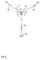
- FIG. 2 is also an exemplary configured device for securing overhead lines, in particular high-voltage overhead lines, specified, which differ from the in Fig. 1 embodiment shown mainly distinguishes in that the two tethers 16 are connected to each other, for example by means of cable ties, corresponding bands or clamps, are dimensioned equal in length and starting from the fuse element 2 vertically down to a common located on the ground fixed and / or anchor point 24th are guided. Since the device shown here in the other features with the FIG. 1 For the sake of further explanation, reference is made to the comments on Fig. 1 directed.
- Such an orientation of the tethers 16 may also be preferred, for example, when the object to be protected is not located centrally below the securing element 2 but, for example, to the left or to the right thereof.
- FIG. 3 is a clamped between two sub-conductors, exemplified device for securing overhead lines with a fuse element 2 with three eyelets 30,36 and two guide cables 12 and a tether 16 is shown.
- This device comprises a securing element 2 with a holding frame 4 with a roller 6 for receiving at least one to be mounted or disassembled overhead line.
- the holding frame 4 has substantially two legs 8, wherein each leg 8 at its upper end in each case has an eyelet 30 for fastening in each case a guide cable 12, which form the first holding means 10.
- a horizontally extending connecting element 34 such as a web 34, rigidly connected to each other.
- a second holding means 14 in the form of a downwardly directed (the ground and / or crossing object) directed eyelet 36 for attachment of a tether 16 is provided. Furthermore, both legs 8 of the holding frame 4 are still connected via a round web and / or bearing pin 22, on which the roller 6 rotatably mounted and / or supported is connected to each other.
- each guide cable 12 is detachably connected via respective terminals 18, each with a sub-line 20 of a transmission system of a power transmission line.
- the securing member 2, in particular attached to the eyelet 36 tether 16 is guided vertically down to a fixed and / or anchor point 24 located at the bottom.
- the respective fixed and / or anchor point can be formed by appropriate fasteners such as ground anchor, Einschlagpfosten, concrete foundation with mounting lugs or hooks or the like.
- Fig. 4 is one opposite Fig. 3 modified embodiment shown which a securing element 2 with a holding frame 4 with two eyelets 30, a guide roller 40 and two guide cables 12 and a tether 16, in a modification to Fig. 3 is provided as a second holding means 14, a guide roller 40 which on which the two legs at their lower (facing the ground) distal end connecting horizontal web 34 is arranged rotatably mounted.
- the tether 16 guided on the securing element 2 via the guide roller 40 is connected with its free ends in each case with a fixed or anchor point on the ground under train, wherein the fixed and / or anchor points 24 are flanking arranged on opposite sides, the respective intersection object.
- the respective fixed and / or anchor point can be formed by a corresponding fastening means such as ground anchor, Einschlagpfosten, concrete foundation with mounting lugs or hooks or the like.
- the at least one tether can also be connected crosswise to the corresponding fixed and / or anchor points.
- the axes of rotation of the roller and the guide roller are perpendicular to each other.
- a further alternative embodiment of a device according to the invention for securing overhead lines is shown, which comprises a securing element 2 with four guide rollers 40, 50a, b and a guide cable 12 and a tether 16.
- This includes a securing element 2 with a support frame 4 with a roller 6 for receiving at least one overhead line to be assembled or disassembled.
- the support frame 4 in this case has essentially two legs 8, which are rotatably mounted and / or supported on its lower (the ground facing) distal end via a horizontal web 34 and a round web and / or bearing pin 22 on which the roller 6 , are rigidly connected.
- the first holding means 10 for receiving and / or guiding the guide cable 12 comprises three guide rollers 50a, b, wherein in each case a guide roller 50a is rotatably mounted at the upper end of each leg 8 and wherein a third guide roller 50b centrally on the two legs connecting web 34th is arranged.
- a third leg 52 is provided, which is arranged centrally with its upper distal end on the web 34 and directed vertically downwards.
- the guide cable 12 is guided in each case via the guide rollers 50a at the ends of the legs 8 and guided under the third guide roller 50b on the web 34.
- a second holding means in the form of another, fourth guide roller 40 for receiving the tether 16 is provided on the third leg 52.
- the tether 16 guided on the securing element 2 via the fourth guide roller 40 of the second holding means 16 has its free ends in each case with a fixed or anchor point connected to the ground under train, wherein the fixed and / or anchor points 24 on opposite sides, the respective crossing object flanking, are arranged.
- the respective fixed and / or anchor point can be formed by a corresponding fastening means such as ground anchor, Einschlagpfosten, concrete foundation with mounting lugs or hooks or the like.
- the at least one tether can also be connected crosswise to the corresponding fixed and / or anchor points.
- the axis of rotation of the roller 6 is perpendicular to the axes of rotation of the guide rollers 40, 50a, aligned.
- the ropes used are made of insulating material, so that in every situation a current of not more than 500 ⁇ A can flow.
- the running surface of both the roller 6 and the guide rollers 40, 50a, b is concave and or conical in order to allow a better cable guide.
- the running surface is that surface of a roll which is in contact or comes into contact with the respective rope.
- the dimensions of the guide rollers 40, 50a, b are adapted to the thickness or the diameter of the at least one guide cable.
- a V-shaped securing element 2 with two legs 8 is shown, which enclose an angle of less than 90 ° and are rigidly connected to one another by at least one web and / or bearing pin 22 for the rotatable mounting of the roller.
- a first holding means 10 is provided in the form of a fastening eye 36.
- the two legs 8 converge in a point, in the region of a second holding means 14 for receiving / fixing a tether 16 is provided.
- a movable or displaceable on / on the guide cable arranged securing element 2 allows a simple positioning of the same, in particular from the ground and / or subsequently, that is even after mounting already done.
- the tether 15 can be tightened when needed a guide roller 40 if necessary in a simple manner from the ground and / or decreased.
- the present invention is by no means limited to the embodiments set forth here, but rather any combination of holding means, such as rollers and / or eyelets, and geometric configurations of the holding frame and / or the bearing is included.
Landscapes
- Suspension Of Electric Lines Or Cables (AREA)
Applications Claiming Priority (1)
| Application Number | Priority Date | Filing Date | Title |
|---|---|---|---|
| DE200710041763 DE102007041763A1 (de) | 2007-09-04 | 2007-09-04 | Sicherungselement, Vorrichtung und Verfahren zur Sicherung von Freileitungen |
Publications (2)
| Publication Number | Publication Date |
|---|---|
| EP2034573A2 true EP2034573A2 (fr) | 2009-03-11 |
| EP2034573A3 EP2034573A3 (fr) | 2011-01-05 |
Family
ID=40090483
Family Applications (1)
| Application Number | Title | Priority Date | Filing Date |
|---|---|---|---|
| EP08015348A Withdrawn EP2034573A3 (fr) | 2007-09-04 | 2008-08-29 | Elément de sécurité, dispositif et procédé de sécurisation de lignes aériennes |
Country Status (2)
| Country | Link |
|---|---|
| EP (1) | EP2034573A3 (fr) |
| DE (1) | DE102007041763A1 (fr) |
Family Cites Families (9)
| Publication number | Priority date | Publication date | Assignee | Title |
|---|---|---|---|---|
| AT233646B (de) * | 1961-07-17 | 1964-05-25 | Starkstrom Anlagen Elek Fizier | Montagewagen für Freileitungen mit Bündelleitern |
| FR1339937A (fr) * | 1962-11-26 | 1963-10-11 | Procédé et appareillage permettant d'enjamber des lignes électriques, des routes, des cours d'eau et analogues, au cours de l'installation de lignes électriques | |
| JPH0755011B2 (ja) * | 1987-10-30 | 1995-06-07 | 三和テッキ株式会社 | 自動開閉凧取器 |
| FR2675964B1 (fr) * | 1991-04-29 | 1995-03-10 | Electricite De France | Nacelle heliportee et procede de remplacement d'un manchon sur un cable aerien. |
| JPH0823610A (ja) * | 1994-07-05 | 1996-01-23 | Chubu Electric Power Co Inc | 電線工事用器具の吊下げ具 |
| GB2299351A (en) * | 1995-01-25 | 1996-10-02 | Edward Christopher Holt | Crossing equipment |
| GB2299219B (en) * | 1995-03-24 | 1999-06-30 | Manx Electricity Authority | Methods for use in installing overhead conductors |
| GB9724236D0 (en) * | 1997-11-18 | 1998-01-14 | Fleury Rejean | Bundle conductor supporting block |
| GB9817009D0 (en) * | 1998-08-06 | 1998-09-30 | Amec Power Limited | Replacement of overhead power lines |
-
2007
- 2007-09-04 DE DE200710041763 patent/DE102007041763A1/de not_active Withdrawn
-
2008
- 2008-08-29 EP EP08015348A patent/EP2034573A3/fr not_active Withdrawn
Also Published As
| Publication number | Publication date |
|---|---|
| DE102007041763A1 (de) | 2009-03-05 |
| EP2034573A3 (fr) | 2011-01-05 |
Similar Documents
| Publication | Publication Date | Title |
|---|---|---|
| DE102007041762B4 (de) | Sicherungselement, Vorrichtung und Verfahren zur Sicherung von Freileitungen | |
| EP2631107B1 (fr) | Dispositif de réglage de tension pour caténaires à bandes électriques | |
| EP2034573A2 (fr) | Elément de sécurité, dispositif et procédé de sécurisation de lignes aériennes | |
| DE102018114357A1 (de) | Vorrichtung zum Halten und Herabführen von Leiterseilen einer Freileitung | |
| DE19937003B4 (de) | Verfahren und Vorrichtung zur Demontage von Freileitungsseilen | |
| DE10240432B4 (de) | Führungsrolle für Fahrdrahtzug am Seitenhalter | |
| AT399618B (de) | Anordnung zum schutze gegen die folgen des brechens eines isolators von doppelisolatorenhängeketten von hochspannungs-freileitungen | |
| DE1934510A1 (de) | Anschluss- und Befestigungseinrichtung fuer Profilstromleiter | |
| DE102011001398A1 (de) | Freileitungseinrichtung, insbesondere für Hochspannungsfreileitungen | |
| DE102006010765B4 (de) | Bandhaken und Weidezaunbreitbandbefestigungsvorrichtung | |
| DE435746C (de) | In ein Kettenwerk eingebaute Vorrichtung zur Streckentrennung oder Nachspannung des Fahrdrahtes mit vom Fahrdraht abgezweigtem, nach aufwaerts gefuehrtem Beidraht | |
| DE102019218484B4 (de) | Isolator zum Halten eines länglichen, elektrisch leitenden Zaunelements | |
| DE390196C (de) | Vielfachaufhaengung unter Bauwerken geringer Hoehe | |
| DD223025A1 (de) | Anordnung zum halten von seilschlaufen oder steilverbindungen | |
| DD281061A1 (de) | Vorrichtung zur montage von leiterseilen | |
| DE4135120A1 (de) | Daempfungseinrichtung | |
| DE102015119357A1 (de) | Sicherungssystem zum Sichern von Personen auf Containern | |
| DE568245C (de) | Zusatzaufhaengung bzw. -abspannung fuer elektrische Freileitungen zur Daempfung mechanischer Schwingungen | |
| EP2384453A2 (fr) | Installation d'un guide d'ondes optique dans un dispositif de transmission d'énergie | |
| EP3118054A1 (fr) | Suspension de barrette de connexion sur des poutres | |
| DE3028037A1 (de) | Aufhaengung fuer ein luftkabel an einem freileitungsseil | |
| DE102022108802A1 (de) | Arbeitssitz, Haltevorrichtung und Verfahren zum Montieren und/oder Demontieren von Leiterseilen | |
| DE2461318A1 (de) | Rollengehaenge und verfahren zum verlegen und zum demontieren von freileitungsseilen | |
| DE10015132A1 (de) | Verfahren und Vorrichtung zur Stromübertragung | |
| DE202005010579U1 (de) | Freileitungsmast |
Legal Events
| Date | Code | Title | Description |
|---|---|---|---|
| PUAI | Public reference made under article 153(3) epc to a published international application that has entered the european phase |
Free format text: ORIGINAL CODE: 0009012 |
|
| AK | Designated contracting states |
Kind code of ref document: A2 Designated state(s): AT BE BG CH CY CZ DE DK EE ES FI FR GB GR HR HU IE IS IT LI LT LU LV MC MT NL NO PL PT RO SE SI SK TR |
|
| AX | Request for extension of the european patent |
Extension state: AL BA MK RS |
|
| PUAL | Search report despatched |
Free format text: ORIGINAL CODE: 0009013 |
|
| AK | Designated contracting states |
Kind code of ref document: A3 Designated state(s): AT BE BG CH CY CZ DE DK EE ES FI FR GB GR HR HU IE IS IT LI LT LU LV MC MT NL NO PL PT RO SE SI SK TR |
|
| AX | Request for extension of the european patent |
Extension state: AL BA MK RS |
|
| 17P | Request for examination filed |
Effective date: 20110119 |
|
| AKX | Designation fees paid |
Designated state(s): AT BE BG CH CY CZ DE DK EE ES FI FR GB GR HR HU IE IS IT LI LT LU LV MC MT NL NO PL PT RO SE SI SK TR |
|
| STAA | Information on the status of an ep patent application or granted ep patent |
Free format text: STATUS: THE APPLICATION IS DEEMED TO BE WITHDRAWN |
|
| 18D | Application deemed to be withdrawn |
Effective date: 20140301 |