EP2034604A1 - Dispositif de commande de machine rotation à courant alternatif - Google Patents
Dispositif de commande de machine rotation à courant alternatif Download PDFInfo
- Publication number
- EP2034604A1 EP2034604A1 EP06767607A EP06767607A EP2034604A1 EP 2034604 A1 EP2034604 A1 EP 2034604A1 EP 06767607 A EP06767607 A EP 06767607A EP 06767607 A EP06767607 A EP 06767607A EP 2034604 A1 EP2034604 A1 EP 2034604A1
- Authority
- EP
- European Patent Office
- Prior art keywords
- rotary machine
- axis
- command
- control
- current
- Prior art date
- Legal status (The legal status is an assumption and is not a legal conclusion. Google has not performed a legal analysis and makes no representation as to the accuracy of the status listed.)
- Withdrawn
Links
Images
Classifications
-
- H—ELECTRICITY
- H02—GENERATION; CONVERSION OR DISTRIBUTION OF ELECTRIC POWER
- H02P—CONTROL OR REGULATION OF ELECTRIC MOTORS, ELECTRIC GENERATORS OR DYNAMO-ELECTRIC CONVERTERS; CONTROLLING TRANSFORMERS, REACTORS OR CHOKE COILS
- H02P21/00—Arrangements or methods for the control of electric machines by vector control, e.g. by control of field orientation
-
- H—ELECTRICITY
- H02—GENERATION; CONVERSION OR DISTRIBUTION OF ELECTRIC POWER
- H02P—CONTROL OR REGULATION OF ELECTRIC MOTORS, ELECTRIC GENERATORS OR DYNAMO-ELECTRIC CONVERTERS; CONTROLLING TRANSFORMERS, REACTORS OR CHOKE COILS
- H02P5/00—Arrangements specially adapted for regulating or controlling the speed or torque of two or more electric motors
- H02P5/74—Arrangements specially adapted for regulating or controlling the speed or torque of two or more electric motors controlling two or more AC dynamo-electric motors
-
- H—ELECTRICITY
- H02—GENERATION; CONVERSION OR DISTRIBUTION OF ELECTRIC POWER
- H02P—CONTROL OR REGULATION OF ELECTRIC MOTORS, ELECTRIC GENERATORS OR DYNAMO-ELECTRIC CONVERTERS; CONTROLLING TRANSFORMERS, REACTORS OR CHOKE COILS
- H02P21/00—Arrangements or methods for the control of electric machines by vector control, e.g. by control of field orientation
- H02P21/14—Estimation or adaptation of machine parameters, e.g. flux, current or voltage
- H02P21/141—Flux estimation
-
- H—ELECTRICITY
- H02—GENERATION; CONVERSION OR DISTRIBUTION OF ELECTRIC POWER
- H02P—CONTROL OR REGULATION OF ELECTRIC MOTORS, ELECTRIC GENERATORS OR DYNAMO-ELECTRIC CONVERTERS; CONTROLLING TRANSFORMERS, REACTORS OR CHOKE COILS
- H02P21/00—Arrangements or methods for the control of electric machines by vector control, e.g. by control of field orientation
- H02P21/14—Estimation or adaptation of machine parameters, e.g. flux, current or voltage
- H02P21/18—Estimation of position or speed
-
- H—ELECTRICITY
- H02—GENERATION; CONVERSION OR DISTRIBUTION OF ELECTRIC POWER
- H02P—CONTROL OR REGULATION OF ELECTRIC MOTORS, ELECTRIC GENERATORS OR DYNAMO-ELECTRIC CONVERTERS; CONTROLLING TRANSFORMERS, REACTORS OR CHOKE COILS
- H02P21/00—Arrangements or methods for the control of electric machines by vector control, e.g. by control of field orientation
- H02P21/34—Arrangements for starting
-
- H—ELECTRICITY
- H02—GENERATION; CONVERSION OR DISTRIBUTION OF ELECTRIC POWER
- H02P—CONTROL OR REGULATION OF ELECTRIC MOTORS, ELECTRIC GENERATORS OR DYNAMO-ELECTRIC CONVERTERS; CONTROLLING TRANSFORMERS, REACTORS OR CHOKE COILS
- H02P25/00—Arrangements or methods for the control of AC motors characterised by the kind of AC motor or by structural details
- H02P25/02—Arrangements or methods for the control of AC motors characterised by the kind of AC motor or by structural details characterised by the kind of motor
- H02P25/022—Synchronous motors
- H02P25/024—Synchronous motors controlled by supply frequency
-
- H—ELECTRICITY
- H02—GENERATION; CONVERSION OR DISTRIBUTION OF ELECTRIC POWER
- H02P—CONTROL OR REGULATION OF ELECTRIC MOTORS, ELECTRIC GENERATORS OR DYNAMO-ELECTRIC CONVERTERS; CONTROLLING TRANSFORMERS, REACTORS OR CHOKE COILS
- H02P27/00—Arrangements or methods for the control of AC motors characterised by the kind of supply voltage
- H02P27/04—Arrangements or methods for the control of AC motors characterised by the kind of supply voltage using variable-frequency supply voltage, e.g. inverter or converter supply voltage
Definitions
- This invention relates to a control apparatus for an AC rotary machine wherein the AC rotary machine is controlled by employing a power inverter, and more particularly to a control apparatus for an AC rotary machine wherein a start control for starting the AC rotary machine in a free-run state or the like is performed.
- a cost and wiring which are required for the rotational angular velocity detector can be omitted. Since, however, the rotational angular velocity detector is not employed, the rotational velocity of the AC rotary machine cannot be known when the AC rotary machine starts in a free-run state, that is, in a state where the power inverter stops a power inversion operation and where the AC rotary machine is rotating at any desired rotational velocity, so that a stable start is difficult to be performed without generating large fluctuations in the torque and rotational velocity of the AC rotary machine.
- Patent Document 1 A start method wherein an induction motor is started without employing any rotational angular velocity detector is disclosed in JP 63-077397A (Patent Document 1).
- the instantaneous magnetic flux vector signal and instantaneous generation torque signal of the motor are calculated using switch state signals for commanding the respective phase output voltages of a power inverter, the voltage detection value of a DC voltage source and the current detection value of the motor, and three control flags are generated using the instantaneous magnetic flux vector signal and instantaneous generation torque signal of the motor.
- the switching state of the power inverter is designated so as to generate a voltage vector optimizing a torque response
- the generation torque of the motor is controlled so as to follow up a command value
- a magnetic flux vector is controlled so as to depict an approximate circular locus, so that the induction motor is started from a free-run state.
- the start control the angular frequency of an AC voltage in the power inverter is set higher than the highest angular frequency which arises in a normal operation, and a switch 4 on the DC input side of the power inverter is thereafter closed to pull in the motor.
- the instantaneous magnetic flux vector signal of the induction motor is calculated on the basis of a primary terminal voltage vector value, a primary terminal current vector and a primary winding resistance in the induction motor, and a voltage command for the power inverter is corrected so that this instantaneous magnetic flux vector signal may hold a desired value.
- the induction motor is arranged, for example, outdoors, its temperature fluctuates greatly, and by way of example, it is below the freezing point in midwinter and exceeds 100 °C in the overload continuous operation of the induction motor.
- a control apparatus in Patent Document 1 starts the induction motor by correcting the voltage command for the power inverter so that the instantaneous magnetic vector signal of the induction motor may hold the desired value under the temperature change of the induction motor.
- the temperature change of the induction motor however, a large change arises also in the amplitude of an AC phase current flowing through the induction motor, to incur the drawback that the AC phase current enlarges at the time of the start.
- a situation where a protective function is actuated occurs to bring about a situation where the start of the induction motor cannot be effected.
- the voltage command for the power inverter is corrected so that the instantaneous magnetic flux vector signal may hold the desired value, and hence, the disorder of the output torque of the induction motor arises at the time of the start on account of the delay of the correction, to incur the drawback that a shock and a rotation number fluctuation take place.
- This invention consists in proposing a control apparatus for an AC rotary machine as improves such drawbacks and as can effect a stable start.
- a control apparatus for an AC rotary machine comprises: control means for generating a voltage command on the basis of a current command, and for generating a switching command on the basis of the voltage command; a power inverter which generates an AC output voltage that has its amplitude and its angular frequency controlled on the basis of the switching command; at least one AC rotary machine which is connected to the power inverter; and a current detector which outputs a detection current on the basis of an AC phase current that flows from the power inverter to the AC rotary machine; wherein the control means are configured so as to perform controls including a start control for the AC rotary machine; the control means operate in the start control to calculate a resistance drop component corresponding to a resistance drop of the AC rotary machine on the basis of the detection current, and to adjust the angular frequency of the AC output voltage on the basis of a subtraction output obtained by subtracting the resistance drop component from the voltage command; and the control means simultaneously operate in the start control to adjust an amplitude of the AC output voltage so that an amplitude of
- control means operate in the start control to calculate the resistance drop component corresponding to the resistance drop of the AC rotary machine on the basis of the detection current, and to adjust the angular frequency of the AC output voltage on the basis of the subtraction output obtained by subtracting the resistance drop component from the voltage command, so that the angular frequency of the AC output command of the power inverter can be adjusted without involving a delay as in a prior-art control apparatus wherein a voltage command for a power inverter is corrected so that an instantaneous magnetic flux vector signal may hold a desired value.
- the amplitude of the AC output voltage of the power inverter is adjusted so that the amplitude of the AC phase current flowing from the power inverter to the AC rotary machine may change in conformity with the predetermined function, so that even under the temperature change of the AC rotary machine, the large change of the amplitude of the AC phase current is suppressed, and the AC rotary machine can be stably started.
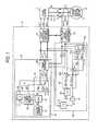
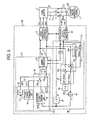
- FIG. 1 is a block diagram showing Embodiment 1 of a control apparatus for an AC rotary machine according to this invention.
- the control apparatus for the AC rotary machine in Embodiment 1 includes a power inverter 1, an AC rotary machine 2, a current detector 3, and control means 10.
- the power inverter 1 is, for example, a three-phase power inverter, which performs the power inversion between a DC power and a three phase AC power.
- the power inverter 1 includes three-phase inversion circuits U, V and W which are connected to a DC power source in parallel with one another.
- each of the inversion circuits U, V and W includes a pair of switches on a plus side and a minus side, and AC power feed lines 1u, 1v and 1w of the three phases are connected between the pairs of switches of the respective inversion circuits.
- the power inverter 1 is concretely configured as a three-phase power inverter of variable-voltage and variable-frequency type.
- This power inverter 1 receives switching commands Su*, Sv * and Sw* from the control means 10, and when it inverts the DC power into the three-phase AC power, it generates the three-phase AC power having controlled output voltage and controlled angular frequency, on the basis of the switching commands Su*, Sv* and Sw*.
- the switching commands Su*, Sv* and Sw* are respectively fed to the inversion circuits of the U-phase, V-phase and W-phase, and they turn ON and OFF the pairs of switches of the respective inversion circuits in controlled phases.
- the AC rotary machine 2 is an AC induction machine 2I, concretely an induction motor of the three phases, and it is connected to the power inverter 1 through the AC power feed lines 1u, 1v and 1w of the three phases.
- the current detector 3 is arranged in, for example, the AC power feed lines 1u and 1v, and it generates a detection current idet on the basis of AC phase currents flowing from the power inverter 1 to the AC induction machine 2I, that is, a U-phase current iu and a V-phase current iv.
- the detection current idet contains a U-phase detection current component iudet and a V-phase detection current component ivdet.
- the U-phase detection current component iudet corresponds to the U-phase current iu flowing through the U-phase AC power feed line 1u
- the V-phase detection current component ivdet corresponds to the V-phase current iv flowing through the V-phase AC power feed line 1v.
- the AC rotary machine 2 is the AC induction machine 2I, and hence, AC phase currents iu, iv and iw which flow from the power inverter 1 to the AC induction machine 21 in the start period of the AC rotary machine become excitation currents for the AC induction machine 2I.
- the control means 10 includes voltage command generation means 11, coordinate transformers 31 and 32, and phase signal generation means 40.
- the voltage command generation means 11 generate a voltage command v* on rotating two-axis coordinates which include a d-axis and a q-axis intersecting orthogonally.
- the voltage command v* contains a d-axis voltage command vd * and a q-axis voltage command vq *.
- the voltage command generation means 11 include start current command means 12, post-start current command means 15, changeover means 18, and a current controller 20.
- the start current command means 12 is used when the start control of the AC induction machine 2I is performed by the control means 10. At the time when the power inverter 1 stops a power inversion operation and when the AC induction machine 2I is in a free-run state, the start control is used for starting the power inverter 1 and beginning the power inversion operation thereof, so as to start the AC induction machine 21 by the power inverter 1.
- This start control is executed in that period of the start period SP before an armature magnetic flux ⁇ rises in the AC induction machine 2I.
- the start period SP is concretely several tens milliseconds to several hundred milliseconds, and it is set at, for example, 100 milliseconds, namely 100 (msec) in Embodiment 1.
- the start current command means 12 generates a start current command il * in the start period SP.
- the start current command means 12 includes a function generator 13 and a band-pass filter 14, and it generates the start current command il *.
- the start current command i * contains a d-axis start current command id1 * and a q-axis start current command iq1 * .
- the band-pass filter 14 is connected to the function generator 13, and it generates the d-axis start current command id1 * .
- the post-start current command means 15 is used instead of the start current command means 12 by changing-over the changeover means 18 after the completion of the start.
- the post-start current command means 15 generates a post-start current command i2 * .
- the post-start current command i2 * contains a d-axis current command id2 * and a q-axis current command iq2 *.
- the post-start current command means 15 have a d-axis current command unit 16 and a proportional gain multiplier 17.
- the d-axis current command unit 16 generates the post-start d-axis current command id2 *.
- the changeover means 18 perform changeover from the start current command means 12 to the post-start current command means 15 after the lapse of the start period SP.
- the changeover means 18 feeds the start current command i1 * as a current command I * from the start current command means 12 to the current controller 20, and after the lapse of the start period SP, it feeds the current command i2 * as the current command I * from the post-start current command means 15 to the current controller 20.
- the changeover means 18 includes a d-axis changeover switch 18d and a q-axis changeover switch 18q.
- the d-axis changeover switch 18d performs the changeover between the d-axis start current command id1 * and the post-start d-axis current command id2 * .
- the q-axis changeover switch 18q performs the changeover between the q-axis start current command iq1 * and the post-start q-axis current command iq2 *.
- the changeover switches 18d and 18q are changed-over in interlocking with each other.
- the changeover switch 18d selects the d-axis start current command id1 * and feeds this d-axis start current command id1 * to the current controller 20 as a d-axis current command id *
- the changeover switch 18q selects the q-axis start current command iq1 * and feeds this q-axis start current command iq1 * to the current controller 20 as a q-axis current command iq * .
- both the changeover switches 18d and 18q are changed-over, and the changeover switch 18d selects the post-start d-axis current command id2 * and feeds this d-axis current command id2 * to the current controller 20 as the d-axis current command id * , while the changeover switch 18q selects the post-start q-axis current command iq2 * and feeds this q-axis current command iq2 * to the current controller 20 as the q-axis current command iq * .
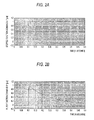
- FIG. 2A shows a stepped function command is which is output from the function generator 13 of the start current command means 12, while FIG. 2B exemplifies a filter function command if* which is output from the band-pass filter 14 on the basis of the stepped function command is * .
- the filter function command if * is output as the d-axis start current command id1 * .
- the axes of abscissas are a common time axis.
- the stepped function command is * from the function generator 13 is in a stepped waveform which rises at a time of 0.1 (second), but the filter function command if * which is output from the band-pass filter 14 decreases with the lapse of time.
- the control range of the angular frequency of the AC induction machine 2I has been set at 1 to 60 (Hz)
- the pass bandwidth of the band-pass filter 14 has been set at 1 to 60 (Hz) in conformity therewith.
- the stepped function command is * from the function generator 13 is fed to the current controller 20 as the d-axis start current command id 1 * .
- the AC rotary machine 2 is the AC induction machine 2I and where this AC induction machine 2I is started, it suffices to command a voltage and a current which contain the rotational angular frequency component of the AC induction machine 21, and the AC induction machine 2I can be started without feeding any frequency component other than the frequency necessary for the commands.
- the stepped function command is * from the function generator 13 as shown in FIG.
- the d-axis start current command id1 * of larger magnitude can be given by setting the filter function command if * from the band-pass filter 14 as the d-axis start current command id1 * , than by setting the stepped function command is from the function generator 13 as the d-axis start current command id1 * , whereby the precision of the detection current idet to be obtained from the AC rotary machine 2 is enhanced more. Also, the precision of the calculation of the angular frequency ⁇ by the phase signal generation means 40 can be enhanced more. In this manner, the band-pass filter 14 generates the filter function command if* with the unnecessary signal components cut, so that the AC rotary machine 2 can be efficiently started without feeding any wasteful current command component unnecessary for the start, in the start period SP.
- the function generator 13 has been described as generating the stepped function command is *
- an M-series signal or a pseudo-noise signal utilizing a random number table can also be generated instead of the stepped function command is * .
- the band-pass filter 14 passes only the frequency component necessary for the start and generates the filter function command if * , so that the start can be efficiently effected without feeding any wasteful current component for the start.
- the coordinate transformer 31 is a coordinate transformer from the rotating two-axis coordinates which include the d-axis and q-axis intersecting orthogonally, into the three-phase time coordinates, and it receives the voltage command v * and generates the switching commands Su * , Sv * and Sw * .
- the switching commands Su * , Sv * and Sw * are fed to the power inverter 1.
- the coordinate transformer 32 is a coordinate transformer from the three-phase time coordinates into the rotating two-axis coordinates which include the d-axis and q-axis intersecting orthogonally, and it receives the detection current idet from the current detector 3 and transforms them into a detection current i on the rotating two-axis coordinates which include the d-axis and q-axis intersecting orthogonally.
- the detection current i on the rotating two-axis coordinates contains a d-axis detection current id and a q-axis detection current iq,
- Both the d-axis detection current id and the q-axis detection current iq are fed to the current controller 20 of the voltage command generation means 11.
- the current controller 20 receives the d-axis detection current id and q-axis detection current iq together with the d-axis current command id * and q-axis current command iq * , and it generates the d-axis voltage command vd * and q-axis voltage command vq * so as to equalize the d-axis detection current id to the d-axis current command id * and to equalize the q-axis detection current iq to the q-axis current command iq * .
- the control means 10 uses the start current command means 12, it generates the voltage command v * on the basis of the start current command i1 * of the start current command means I2, and it generates the switching commands Su * , Sv * and Sw * by the coordinate transformer 31 on the basis of the voltage command v * , so as to start the power inverter 1.
- the AC phase currents iu, iv and iw which flow from the power inverter 1 to the AC induction machine 2I become the excitation currents for the AC induction machine 2I, and the amplitude of the AC phase currents iu, iv and iw is determined by the start current command i 1 * .
- the d-axis start current command id 1 * is set as the filter function command if* output from the band-pass filter 14, and the q-axis current command iq1 * is set at zero.
- ia a ⁇ id * 2 + iq * 2 1 / 2
- a denotes a constant.
- the amplitude of the AC phase currents iu, iv and iw is determined by the d-axis start current command id1 * as indicated by Formula (2).
- the AC rotary machine 2 such as the AC induction machine 21 is arranged, for example, outdoors, its temperature fluctuates greatly, and by way of example, it is below the freezing point in midwinter and exceeds 100 °C in an overload continuous operation of the AC rotary machine 2, so that the armature resistance R of the AC rotary machine 2 fluctuates greatly with the change of the temperature.
- the amplitude of the AC phase currents iu, iv and iw is determined by the d-axis start current command id1 * in the start period SP, thereby to perform a current control by the current controller 20, so that the temperature change of the AC rotary machine 2 is not influential.
- the start period SP accordingly, the amplitude of the AC phase currents iu, iv and iw does not change greatly with the temperature change of the AC rotary machine 2, a situation where a protective function operates does not occur, and the AC rotary machine 2 can be stably started.
- This phase signal generation means 40 includes means 41 for calculating the resistance drop of the AC rotary machine 2, subtraction means 43, an integrator 45, a divider 46, and an integrator 47.
- the resistance drop calculation means 41 includes a d-axis resistance drop calculator 41d, and a q-axis resistance drop calculator 41q.
- the d-axis resistance drop calculator 41 d is fed with the d-axis detection current id from the coordinate transformer 32, and it multiplies this d-axis detection current id by the armature resistance R of the AC rotary machine 2, thereby to output a d-axis resistance drop component (R ⁇ id).
- the q-axis resistance drop calculator 41 q is fed with the q-axis detection current iq from the coordinate transformer 32, and it multiplies this q-axis detection current iq by the armature resistance R of the AC rotary machine 2, thereby to output a q-axis resistance drop component (R ⁇ iq).
- the subtraction means 43 includes a d-axis subtractor 43d, and a q-axis subtractor 43q.
- the d-axis subtractor 43d is fed with the d-axis voltage command vd * from the current controller 20, and with the d-axis resistance drop component (R ⁇ id) from the d-axis resistance drop calculator 41d.
- This d-axis subtractor 43d subtracts the d-axis resistance drop component (R ⁇ id) from the d-axis voltage command vd * , thereby to deliver the subtraction output (vd * - R ⁇ id) between them.
- the q-axis subtractor 43q is fed with the q-axis voltage command vq * from the current controller 20, and with the q-axis resistance drop component (R ⁇ iq) from the q-axis resistance drop calculator 41q.
- This q-axis subtractor 43q subtracts the q-axis resistance drop component (R ⁇ iq) from the d-axis voltage command vq * , thereby to deliver the subtraction output (vd * - R ⁇ iq) between them.
- the integrator 45 is fed with the subtraction output (vd * - R ⁇ id) from the d-axis subtractor 43d.
- the integrator 45 integrates this subtraction output (vd * - R ⁇ id), and delivers an integral output ⁇ d.
- This integral output ⁇ d corresponds to a d-axis component ⁇ d at the time when the armature magnetic flux ⁇ of the AC rotary machine 2 is decomposed into the d-axis component ⁇ d and a q-axis component ⁇ q on the rotating two-axis coordinates which include the d-axis and q-axis intersecting orthogonally, and when the q-axis component ⁇ q is made zero.
- the divider 46 is fed with the subtraction output (vq * - R ⁇ iq) from the q-axis subtractor 43q, and with the integral output ⁇ d from the integrator 45.
- the divider 46 divides the subtraction output (vq * - R ⁇ iq) by the integral output ⁇ d, thereby to generate a division output ⁇ .
- the integrator 47 is fed with the division output ⁇ from the divider 46, and it integrates this division output ⁇ , thereby to generate a phase signal ⁇ .
- This division output ⁇ corresponds to the phase ⁇ of the AC output voltage which is output from the power inverter 1 when the q-axis component ⁇ q of the armature magnetic flux ⁇ of the AC rotary machine 2 is made zero.
- This phase signal ⁇ is fed to the coordinate transformers 31 and 32.
- the coordinate transformer 31 transforms the voltage command v * on the rotating two-axis coordinates which include the d- and q-axes intersecting orthogonally, into the switching commands Su * , Sv * and Sw * on the three-phase time coordinates, and using the phase signal ⁇ , the coordinate transformer 32 transforms the detection currents iudet and ivdet on the three-phase time axis, into the detection currents id and iq on the d- and q-axes of the rotating two-axis coordinates which include the d- and q-axes intersecting orthogonally.
- the d-axis resistance drop component (R ⁇ id) and q-axis resistance drop component (R ⁇ iq) of the AC rotary machine 2 are calculated on the basis of the detection current idet detected by the current detector 3, the d-axis resistance drop component (R ⁇ id) and q-axis resistance drop component (R ⁇ iq) are respectively subtracted from the d-axis voltage command vd * and q-axis voltage command vq * , and the angular frequency ⁇ of the AC phase currents iu, iv and iw flowing to the AC rotary machine 2 is calculated on the basis of the subtraction outputs (vd * - R ⁇ id) and (vq * - R ⁇ iq), so that the angular frequency of the AC output voltage to be output from the power inverter 1 can be adjusted so as to agree with the angular frequency of the AC phase currents iu, iv
- vd * and vq * denote the voltage commands on the rotating two-axis coordinates as are generated by the current controller 20 of the voltage command generation means 11
- id and iq denote the detection currents obtained in such a way that the detection currents iudet and iv
- ⁇ m Pm ⁇ ⁇ d ⁇ iq - ⁇ q ⁇ id
- Pm denotes the number of pair poles of the AC rotary machine 2.
- the phase signal generation means 40 calculates the angular frequency ⁇ in conformity with Formulas (7), (8) and (9).
- the d-axis subtractor 43d calculates (vd * - R ⁇ id) in Formula (7), and the integrator 45 calculates the d-axis component ⁇ d of the armature magnetic flux ⁇ as is expressed by Formula (7).
- the q-axis subtractor 43q calculates (vq * - R ⁇ iq) in Formula (9), and the divider 47 calculates the angular frequency ⁇ expressed by Formula (9).
- the phase signal ⁇ is calculated on the basis of the angular frequency ⁇ , and it controls the coordinate transforms of the coordinate transformers 31 and 32.
- the angular frequency of the AC output voltage to be output from the power inverter 1 is controlled so as to equalize to the rotational angular frequency of the rotating two-axis coordinates, in correspondence with the rotational angular frequency ⁇ of the rotating two-axis coordinates, so that the angular frequency of the AC output voltage to be output from the power inverter 1 is adjusted so as to agree with the angular frequency of the AC phase currents iu, iv and iw flowing to the AC rotary machine.
- the angular frequency ⁇ of the rotating two-axis coordinates is controlled by the phase signal ⁇ for the coordinate transformers 31 and 32, so that the angular frequency of the AC output voltage to be output from the power inverter 1 can be brought into agreement with the angular frequency of the AC phase currents iu, iv and iw flowing to the AC rotary machine 2, without any delay.
- the output torque ⁇ m of the AC rotary machine 2 is made zero, and the AC rotary machine 2 in a free-run state is started, whereby the output torque of the AC rotary machine 2 is prevented from fluctuating in the start period SP, and the occurrences of a shock and a rotation number fluctuation in the AC rotary machine 2 can be suppressed.
- the angular frequency of the output voltage of the power inverter is corrected on the basis of the angular frequency ⁇ , and hence, a shaft deviation arises due to the delay of the correction.
- the shaft deviation ascribable to the delay of the correction is eliminated, and the AC rotary machine 2 can be started with the shock and the rotation number fluctuation suppressed.
- the start current command i1* to be fed to the current controller 20 is afforded from the start current command means 12 irrespective of the armature resistance R of the AC rotary machine 2, so as to determine the amplitude of the AC phase currents iu, iv and iw. Accordingly, even when the armature resistance R of the AC rotary machine 2 has changed depending upon the temperature condition of the AC rotary machine 2, the start current command i1 * is not influenced by the armature resistance R.
- the start is effected in such a way that the q-axis start current command iq1 * in the start period SP is held at zero by the start current command means 12, and that the initial value of the q-axis voltage command vq * in the start period SP as is generated by the current controller 20 is made zero.
- the subtraction output (vq * - R ⁇ iq) of the q-axis subtractor 43q becomes zero, and also the division output ⁇ of the divider 46 becomes zero.
- the angular frequency ⁇ becomes zero at the start time point of the start period SP, and this angular frequency ⁇ rises with the lapse of the start period SP.
- the angular frequency of the power inverter is set to be higher than the highest angular frequency which arises in the normal operation of the power inverter.
- the angular frequency of the power inverter needs to be set at the frequency higher than the highest angular frequency after it is set to be either plus or minus, with the result that a start response becomes different in accordance with the rotating direction of the AC rotary machine.
- the start is performed by making the angular frequency ⁇ of the power inverter 1 zero at the start time point of the start period SP, so that the stable start can be always effected irrespective of the rotating direction of the AC rotary machine 2.
- the q-axis start current command iq1 * is held at zero in the start period SP in Embodiment 1, a similar advantage can be obtained even when the q-axis start current command iq1 * is held at a predetermined value other than zero in the start period SP.
- the d-axis component ⁇ d of the armature magnetic flux ⁇ enlarges from zero with the increase of the d-axis start current command id1 *
- the output torque ⁇ m of the AC rotary machine 2 enlarges with the increase of the d-axis component ⁇ d of the armature magnetic flux.
- the d-axis start current command id1 * enlarges from zero, with the result that also the output torque ⁇ m of the AC rotary machine 2 enlarges from zero, and the AC rotary machine 2 can be stably started with a large shock and a sudden rotation number fluctuation suppressed.
- Embodiment 1 consists in starting the AC rotary machine 2 when the AC rotary machine 2 is in its free-run state
- Embodiment 2 consists in starting the AC rotary machine 2 when whether the AC rotary machine 2 is in its free-run state or its stop state cannot be discriminated.
- the control means 10 have the same configuration as in Embodiment 1, and it starts the power inverter 1 so as to start the AC rotary machine 2.
- a start control at the time when the AC rotary machine 2 is in the free-run state is the same as in Embodiment 1, and also in a case where the AC rotary machine 2 is in the stop state, a stable start can be effected in the same manner as in Embodiment 1.
- the rotational angular frequency of the AC rotary machine 2 is zero at the start time point of the start period SP, and also the angular frequency ⁇ calculated by the phase signal generation means 40 becomes zero, but with the start of the power inverter 1, the armature magnetic flux ⁇ of the AC rotary machine 2 rises gradually, and the stable start can be effected.
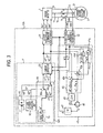
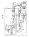
- FIG. 3 is a block diagram showing Embodiment 3 of a control apparatus for an AC rotary machine according to this invention.
- Embodiment 3 is such that the control means 10 in Embodiment 1 are replaced with control means 10A, in which the start current command means 12 in Embodiment 1 are replaced with start current command means 12A.
- a band-pass filter 14 is removed, and a stepped function command is * is fed from the function generator 13 to the current controller 20 through the d-axis changeover switch 18d of changeover means 18 as the d-axis start current command id1 * .
- the others are the same in configuration as in Embodiment 1 or 2.
- Embodiment 3 the wasteful component of the start current command id1 * cannot be cut by the band-pass filter 14, but the same advantages as in Embodiment 1 or Embodiment 2 can be obtained as to the others.
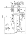
- FIG. 4 is a block diagram showing Embodiment 4 of a control apparatus for an AC rotary machine according to this invention.
- a synchronous machine 2S is used as the AC rotary machine 2.
- This synchronous machine 2S is concretely a three-phase synchronous motor by way of example.
- the q-axis start current command iq1 * 0 is fed to the current controller 20 through the q-axis changeover switch 18q of the changeover means in the same manner as in Embodiment 1.
- the others are the same in configuration as in Embodiment 1.
- the AC rotary machine 2 is the induction machine 2I in Embodiment 1, and for starting the induction machine 2I which is in the free-run state, it is necessary to feed the voltage and current of the rotational angular velocity component to the induction machine 2I.
- an induced voltage caused by a rotor is generated in the synchronous machine 2S, and hence, the voltage and current of the rotational angular velocity component need not be fed from the power inverter 1, so that the d-axis start current command id1 * is held at zero.
- phase signal generation means 40 calculates the angular frequency ⁇ on the basis of the AC phase currents iu, iv and iw, and the angular frequency of the AC output voltage of the power inverter 1 is controlled on the basis of the angular frequency ⁇ .
- the d-axis start current command id1 * is made zero, whereby the synchronous machine 2S can be efficiently started without feeding any wasteful current to the synchronous machine 2S.
- the q-axis start current command iq1 * is made zero in the same manner as in Embodiment 1, it can also be made a predetermined value other than zero.
- FIG. 5 is a block diagram showing Embodiment 5 of a control apparatus for an AC rotary machine according to this invention. Also Embodiment 5 uses a synchronous machine 2S as the AC rotary machine 2, likewise to Embodiment 4.
- control means 10B in Embodiment 4 is replaced with control means 10C, in which the start current command means 12B in Embodiment 4 is replaced with start current command means 12C.
- start current command means 12C a d-axis start current command unit 19 is used, and the d-axis start current command unit 19 is fed from this d-axis start current command id1 * to the current controller 20 through the d-axis changeover switch 18d of changeover means 18.
- the others are the same in configuration as in Embodiment 4.
- the d-axis start current command unit 19 brings the d-axis start current command id1 * to (A - B/ ⁇ ), namely on the basis of the external command io.
- this d-axis start current command unit 19 when the absolute value of the angular frequency ⁇ is smaller than ⁇ BASE, the synchronous machine 2S is efficiently started without feeding any wasteful current to the synchronous machine 2S in order to start this synchronous machine 2S, and when the absolute value of the angular frequency ⁇ is equal to or larger than ⁇ BASE, a magnetic flux weakening control is performed by setting (A - B/ ⁇ ) at a negative value, whereby the voltage saturation of a power inverter 1 can be prevented.
- the q-axis start current command iq1 * is made zero in the same manner as in Embodiment 1, it can also be made a predetermined value other than zero.
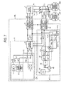
- FIG. 6 is a block diagram showing Embodiment 6 of a control apparatus for an AC rotary machine according to this invention.
- Embodiment 6 is such that two AC rotary machines, concretely two induction machines 2I1 and 2I2 are connected to a power inverter 1 in parallel with each other.
- the induction machines 2I1 and 2I2 are three-phase induction motors whose ratings are equal to each other, and they are carried on, for example, an electric car so as to drive the electric car.
- the induction machines 2I1 and 2I2 have armature resistances R which are equal to each other. Since these induction machines 2I1 and 212 are connected to the power inverter 1 in parallel to each other, the combined armature resistance thereof as seen from the power inverter 1 becomes (R/2).
- the control means 10 in Embodiment 1 is replaced with control means 10D, in which the phase signal generation means 40 in Embodiment 1 is replaced with phase signal generation means 40D.
- This phase signal generation means 40D has a resistance drop calculation circuit 41D, which has a d-axis resistance drop calculator 411d and a q-axis resistance drop calculator 411q.
- the others are the same in configuration as in Embodiment 1.
- the d-axis resistance drop calculator 41 1d is fed with the d-axis detection current id from the coordinate transformer 32, and it multiplies this d-axis detection current id by (R/2) so as to output a d-axis resistance drop ⁇ (R/2) ⁇ id ⁇ .
- the q-axis resistance drop calculator 411 q is fed with the q-axis detection current iq from the coordinate transformer 32, and it multiplies this q-axis detection current iq by (R/2) so as to output a q-axis resistance drop ⁇ (R/2) ⁇ iq ⁇ .
- the d-axis subtractor 43d delivers a subtraction output ⁇ vd * - (R/2) ⁇ id ⁇
- the q-axis subtractor 43q delivers a subtraction output ⁇ vq * - (R/2) ⁇ iq ⁇
- the phase signal generation means 40D in Embodiment 6 calculates the angular frequency ⁇ in conformity with Formula (11), and the angular frequency of the AC output voltage of the power inverter 1 is controlled so as to become equal to this angular frequency ⁇ . Also in Embodiment 6, the two induction machines 2I1 and 2I2 in free-run states can be stably started in the same manner as in Embodiment 1. In a case where three or more induction machines are connected to the power inverter 1 in parallel, the multiplication coefficient in the resistance drop calculation circuit 41D is adjusted in accordance with the number of the connected machines, whereby the three or more induction machines in free-run states can be stably started similarly.
- FIG. 7 is a block diagram showing Embodiment 7 of a control apparatus for an AC rotary machine according to this invention.
- Embodiment 7 is such that two AC rotary machines, concretely two synchronous machines 2S1 and 2S2 are connected to a power inverter 1 in parallel with each other.
- the synchronous machines 2S1 and 2S2 are, for example, three-phase synchronous motors whose ratings are equal to each other.
- the control means 10D in Embodiment 6 is replaced with control means 10E, in which the start current command means 12 of the control means 10D is replaced with start current command means 12B.
- This start current command means 12B is the same as in Embodiment 4.
- the others are the same in configuration as in Embodiment 6.
- any circulating current does not flow between these synchronous machines 2S1 and 2S2. If the synchronous machines 2S1 and 2S2 have no load in the case of starting the synchronous machines 2S1 and 2S2 which are in the free-run states, a state where the circulating current does not flow between these synchronous machines 2S1 and 2S2 is a stable state, and the synchronous machines 2S1 and 2S2 are started in this stable state.
- a combined armature resistance seen from the power inverter 1 becomes (R/2), and hence, the two synchronous machines 2S1 and 2S2 being in the free-run states can be stably started in the same manner as in Embodiment 4, by employing the same phase signal generation means 40 as in Embodiment 6.
- the multiplication coefficient in the resistance drop calculation circuit 41D is adjusted in accordance with the number of the connected machines, whereby the three or more synchronous machines in free-run states can be stably started similarly.
- a control apparatus for an AC rotary machine according to this invention is applied to a control apparatus for the AC rotary machine such as an induction machine or a synchronous machine.
Landscapes
- Engineering & Computer Science (AREA)
- Power Engineering (AREA)
- Control Of Ac Motors In General (AREA)
Applications Claiming Priority (1)
| Application Number | Priority Date | Filing Date | Title |
|---|---|---|---|
| PCT/JP2006/312990 WO2008001445A1 (fr) | 2006-06-29 | 2006-06-29 | Dispositif de commande de machine rotation à courant alternatif |
Publications (2)
| Publication Number | Publication Date |
|---|---|
| EP2034604A1 true EP2034604A1 (fr) | 2009-03-11 |
| EP2034604A4 EP2034604A4 (fr) | 2012-11-14 |
Family
ID=38845220
Family Applications (1)
| Application Number | Title | Priority Date | Filing Date |
|---|---|---|---|
| EP06767607A Withdrawn EP2034604A4 (fr) | 2006-06-29 | 2006-06-29 | Dispositif de commande de machine rotation à courant alternatif |
Country Status (8)
| Country | Link |
|---|---|
| US (1) | US8022660B2 (fr) |
| EP (1) | EP2034604A4 (fr) |
| JP (1) | JP4757306B2 (fr) |
| KR (1) | KR101037519B1 (fr) |
| CN (1) | CN101443995B (fr) |
| CA (1) | CA2654432C (fr) |
| TW (1) | TWI345364B (fr) |
| WO (1) | WO2008001445A1 (fr) |
Cited By (3)
| Publication number | Priority date | Publication date | Assignee | Title |
|---|---|---|---|---|
| EP2779417A3 (fr) * | 2013-03-12 | 2015-06-10 | Semiconductor Components Industries, LLC | Procédé de commande et dispositif correspondant |
| EP2600518A4 (fr) * | 2010-07-27 | 2016-12-28 | Mitsubishi Electric Corp | Appareil de commande pour une machine tournante à courant alternatif |
| EP3171508A1 (fr) * | 2015-11-19 | 2017-05-24 | ENEL-PC Spólka z orgraniczona odpowiedzialnoscia | Procédé pour la commande de scalaire d'un moteur à induction, en particulier au fonctionnement à faible vitesse, et système de commande scalaire destiné à un moteur à induction |
Families Citing this family (25)
| Publication number | Priority date | Publication date | Assignee | Title |
|---|---|---|---|---|
| JP4631936B2 (ja) * | 2008-06-18 | 2011-02-16 | トヨタ自動車株式会社 | 動力出力装置およびその制御方法並びに車両 |
| JP5159465B2 (ja) * | 2008-06-24 | 2013-03-06 | 株式会社東芝 | モータ制御装置および半導体集積回路装置 |
| EP2327015B1 (fr) | 2008-09-26 | 2018-09-19 | Sonova AG | Mise à jour sans fil de dispositifs auditifs |
| WO2010125637A1 (fr) * | 2009-04-27 | 2010-11-04 | 三菱電機株式会社 | Dispositif de conversion de puissance |
| US8415835B2 (en) * | 2010-02-26 | 2013-04-09 | The Invention Science Fund I, Llc | Plug-in power line conditioner |
| JP5043981B2 (ja) * | 2010-04-26 | 2012-10-10 | 三菱電機株式会社 | 電動パワーステアリング装置 |
| JP5534935B2 (ja) * | 2010-05-20 | 2014-07-02 | 株式会社東芝 | 回転センサレス制御装置 |
| JP5707761B2 (ja) * | 2010-07-20 | 2015-04-30 | 日産自動車株式会社 | 欠相診断装置及び欠相診断方法 |
| MX2013000965A (es) * | 2010-07-23 | 2013-04-24 | Mitsubishi Electric Corp | Aparato de control y metodo de control para maquina giratoria de ca. |
| KR101190360B1 (ko) * | 2011-03-08 | 2012-10-16 | 엘에스산전 주식회사 | 유도 전동기의 제동 장치 |
| CN103548253B (zh) * | 2011-05-24 | 2016-04-06 | 三菱电机株式会社 | 电机控制装置 |
| JP5382069B2 (ja) * | 2011-07-04 | 2014-01-08 | 株式会社安川電機 | インバータ装置および電動機ドライブシステム |
| JP5656775B2 (ja) * | 2011-08-31 | 2015-01-21 | 日立オートモティブシステムズ株式会社 | 電力変換装置 |
| JP2013162623A (ja) * | 2012-02-03 | 2013-08-19 | Toshiba Corp | 給電システム |
| EP2752330B1 (fr) * | 2013-01-04 | 2018-03-07 | Visedo Oy | Machine de travail mobile avec control de tension du circuit intermediair |
| JP6375757B2 (ja) * | 2014-07-29 | 2018-08-22 | 株式会社安川電機 | 電動機制御装置、電動機の磁束推定装置および電動機の磁束推定方法 |
| US9948224B1 (en) | 2016-10-17 | 2018-04-17 | General Electric Company | System and method for sensorless control of electric machines using magnetic alignment signatures |
| CN107482987A (zh) * | 2017-08-18 | 2017-12-15 | 迪百仕电机科技(苏州)有限公司 | 一种交流电机控制系统 |
| CN111919377B (zh) | 2018-03-30 | 2024-03-08 | 三菱电机株式会社 | 电机驱动装置以及冷冻循环应用设备 |
| US12525866B2 (en) * | 2021-03-19 | 2026-01-13 | Mitsubishi Electric Corporation | Control device and power conversion device |
| CN116648848B (zh) * | 2021-05-20 | 2025-04-04 | 三菱电机株式会社 | 旋转机控制装置、机器学习装置及推断装置 |
| US12500534B2 (en) * | 2021-08-24 | 2025-12-16 | Mitsubishi Electric Corporation | Rotary machine control device |
| JP2024022952A (ja) * | 2022-08-08 | 2024-02-21 | 株式会社東芝 | 電動機の駆動装置、電動機の駆動方法及び電動機の駆動プログラム |
| JP2024165742A (ja) * | 2023-05-18 | 2024-11-28 | ミネベアパワーデバイス株式会社 | モータ制御装置およびモータ制御方法 |
| CN118646313B (zh) * | 2024-05-23 | 2025-11-04 | 比亚迪股份有限公司 | 一种马达振动频率校准方法、控制器及计算设备 |
Family Cites Families (17)
| Publication number | Priority date | Publication date | Assignee | Title |
|---|---|---|---|---|
| JPH0667273B2 (ja) | 1986-09-17 | 1994-08-24 | 東洋電機製造株式会社 | 誘導電動機の再起動方法 |
| JPH054797U (ja) * | 1991-04-05 | 1993-01-22 | 三菱電機株式会社 | 駆動制御装置 |
| JP3422101B2 (ja) | 1994-11-04 | 2003-06-30 | 富士電機株式会社 | 速度センサレスベクトル制御方法 |
| JPH09140200A (ja) * | 1995-11-13 | 1997-05-27 | Hitachi Ltd | 速度センサレスベクトル制御装置 |
| JP2000253505A (ja) | 1999-02-25 | 2000-09-14 | Railway Technical Res Inst | 速度センサレス制御を用いた電気車制御装置 |
| EP1195611B1 (fr) | 2000-03-27 | 2007-03-07 | Mitsubishi Denki Kabushiki Kaisha | Capteur concu pour detecter l'etat de rotation d'une machine synchrone et procede de detection de l'etat de rotation d'une machine synchrone |
| JP4249916B2 (ja) * | 2000-09-18 | 2009-04-08 | エドワーズ株式会社 | ブラシレスモータの制御回路、ブラシレスモータ装置、及び真空ポンプ装置 |
| JP4380089B2 (ja) | 2001-06-07 | 2009-12-09 | 富士電機システムズ株式会社 | 自由回転中の誘導電動機の回転速度検出方法と再起動方法 |
| JP3672876B2 (ja) * | 2002-02-26 | 2005-07-20 | 株式会社東芝 | ベクトル制御インバータ装置及び回転駆動装置 |
| JP2003259699A (ja) | 2002-03-06 | 2003-09-12 | Toshiba Corp | 電力変換装置 |
| JP4202055B2 (ja) * | 2002-06-13 | 2008-12-24 | 株式会社東芝 | インバータ装置及び洗濯機 |
| JP4198415B2 (ja) * | 2002-08-06 | 2008-12-17 | 株式会社東芝 | ベクトル制御インバータ装置 |
| JP4076882B2 (ja) * | 2003-03-06 | 2008-04-16 | 三菱電機株式会社 | 電気車制御装置 |
| JP4342878B2 (ja) * | 2003-09-03 | 2009-10-14 | 株式会社東芝 | 電気車制御装置 |
| JP3900358B2 (ja) * | 2003-12-15 | 2007-04-04 | 三菱電機株式会社 | 電気車制御装置 |
| CN1283041C (zh) | 2004-09-17 | 2006-11-01 | 清华大学 | 无速度传感器永磁同步电机-空调压缩机系统的控制方法 |
| JP4519864B2 (ja) * | 2007-01-29 | 2010-08-04 | 三菱電機株式会社 | 交流回転機の電気的定数測定方法およびこの測定方法の実施に使用する交流回転機の制御装置 |
-
2006
- 2006-06-29 KR KR1020087030085A patent/KR101037519B1/ko not_active Expired - Fee Related
- 2006-06-29 CA CA2654432A patent/CA2654432C/fr active Active
- 2006-06-29 JP JP2008522248A patent/JP4757306B2/ja active Active
- 2006-06-29 WO PCT/JP2006/312990 patent/WO2008001445A1/fr not_active Ceased
- 2006-06-29 US US12/295,909 patent/US8022660B2/en not_active Expired - Fee Related
- 2006-06-29 CN CN2006800546438A patent/CN101443995B/zh active Active
- 2006-06-29 EP EP06767607A patent/EP2034604A4/fr not_active Withdrawn
- 2006-12-12 TW TW095146387A patent/TWI345364B/zh not_active IP Right Cessation
Cited By (3)
| Publication number | Priority date | Publication date | Assignee | Title |
|---|---|---|---|---|
| EP2600518A4 (fr) * | 2010-07-27 | 2016-12-28 | Mitsubishi Electric Corp | Appareil de commande pour une machine tournante à courant alternatif |
| EP2779417A3 (fr) * | 2013-03-12 | 2015-06-10 | Semiconductor Components Industries, LLC | Procédé de commande et dispositif correspondant |
| EP3171508A1 (fr) * | 2015-11-19 | 2017-05-24 | ENEL-PC Spólka z orgraniczona odpowiedzialnoscia | Procédé pour la commande de scalaire d'un moteur à induction, en particulier au fonctionnement à faible vitesse, et système de commande scalaire destiné à un moteur à induction |
Also Published As
| Publication number | Publication date |
|---|---|
| CN101443995A (zh) | 2009-05-27 |
| WO2008001445A1 (fr) | 2008-01-03 |
| KR101037519B1 (ko) | 2011-05-26 |
| TW200803147A (en) | 2008-01-01 |
| CA2654432C (fr) | 2012-06-05 |
| CN101443995B (zh) | 2011-04-27 |
| TWI345364B (en) | 2011-07-11 |
| US20090251083A1 (en) | 2009-10-08 |
| JPWO2008001445A1 (ja) | 2009-11-26 |
| JP4757306B2 (ja) | 2011-08-24 |
| US8022660B2 (en) | 2011-09-20 |
| CA2654432A1 (fr) | 2008-01-03 |
| EP2034604A4 (fr) | 2012-11-14 |
| HK1129264A1 (en) | 2009-11-20 |
| KR20090009967A (ko) | 2009-01-23 |
Similar Documents
| Publication | Publication Date | Title |
|---|---|---|
| EP2034604A1 (fr) | Dispositif de commande de machine rotation à courant alternatif | |
| JP5098439B2 (ja) | 永久磁石同期電動機のセンサレス制御装置 | |
| US7095209B2 (en) | Method and apparatus to regulate torque provided to loads | |
| WO2016121237A1 (fr) | Dispositif de commande d'onduleur et système d'attaque de moteur | |
| JP5717808B2 (ja) | 同期電動機の電流制御装置 | |
| CA3011360C (fr) | Systemes et procede de commande de machines electrodynamiques a entrainement a frequence variable | |
| JP2022043417A (ja) | 系統併入装置 | |
| JP2013187931A (ja) | モータ制御装置 | |
| JP4402600B2 (ja) | 同期電動機の駆動システム及び同期電動機の駆動方法 | |
| JPH0880098A (ja) | 電動機のベクトル制御装置 | |
| JP2006352957A (ja) | 同期モータの制御装置 | |
| JP4583257B2 (ja) | 交流回転機の制御装置 | |
| JP4651087B2 (ja) | 電動機制御装置 | |
| JP4219362B2 (ja) | 回転機の制御装置 | |
| EP3683958A1 (fr) | Dispositif de commande et procédé de commande pour moteur électrique synchrone | |
| JP5517983B2 (ja) | 交流回転機の制御装置 | |
| JPH08298796A (ja) | 永久磁石形電動機制御方法及び制御装置 | |
| JP2008086098A (ja) | 永久磁石同期電動機の駆動装置 | |
| HK1129264B (en) | Ac rotating machine controller | |
| JP2004180494A (ja) | モータ制御装置 | |
| JP2002152914A (ja) | リニアインダクションモータ電気車の制御装置 | |
| JPH04265684A (ja) | サイクロコンバータによる同期電動機の運転方法および装置 | |
| JP2001169598A (ja) | 同期電動機の制御装置 | |
| KR20050104332A (ko) | 회전기의 제어 장치 |
Legal Events
| Date | Code | Title | Description |
|---|---|---|---|
| PUAI | Public reference made under article 153(3) epc to a published international application that has entered the european phase |
Free format text: ORIGINAL CODE: 0009012 |
|
| 17P | Request for examination filed |
Effective date: 20081217 |
|
| AK | Designated contracting states |
Kind code of ref document: A1 Designated state(s): AT BE BG CH CY CZ DE DK EE ES FI FR GB GR HU IE IS IT LI LT LU LV MC NL PL PT RO SE SI SK TR |
|
| AX | Request for extension of the european patent |
Extension state: AL BA HR MK RS |
|
| DAX | Request for extension of the european patent (deleted) | ||
| A4 | Supplementary search report drawn up and despatched |
Effective date: 20121012 |
|
| RIC1 | Information provided on ipc code assigned before grant |
Ipc: H02P 27/04 20060101ALI20121008BHEP Ipc: H02P 25/02 20060101ALI20121008BHEP Ipc: H02P 21/00 20060101AFI20121008BHEP Ipc: H02P 5/74 20060101ALI20121008BHEP Ipc: H02P 21/14 20060101ALI20121008BHEP |
|
| 17Q | First examination report despatched |
Effective date: 20131010 |
|
| GRAP | Despatch of communication of intention to grant a patent |
Free format text: ORIGINAL CODE: EPIDOSNIGR1 |
|
| RIC1 | Information provided on ipc code assigned before grant |
Ipc: H02P 21/18 20160101ALI20170308BHEP Ipc: H02P 21/34 20160101AFI20170308BHEP Ipc: H02P 21/14 20160101ALI20170308BHEP Ipc: H02P 25/024 20160101ALI20170308BHEP Ipc: H02P 5/74 20060101ALI20170308BHEP |
|
| INTG | Intention to grant announced |
Effective date: 20170324 |
|
| STAA | Information on the status of an ep patent application or granted ep patent |
Free format text: STATUS: THE APPLICATION IS DEEMED TO BE WITHDRAWN |
|
| 18D | Application deemed to be withdrawn |
Effective date: 20170804 |
|
| RIC1 | Information provided on ipc code assigned before grant |
Ipc: H02P 21/14 20160101ALI20170308BHEP Ipc: H02P 21/34 20160101AFI20170308BHEP Ipc: H02P 25/024 20160101ALI20170308BHEP Ipc: H02P 5/74 20060101ALI20170308BHEP Ipc: H02P 21/18 20160101ALI20170308BHEP |
|
| RIC1 | Information provided on ipc code assigned before grant |
Ipc: H02P 5/74 20060101ALI20170308BHEP Ipc: H02P 25/024 20160101ALI20170308BHEP Ipc: H02P 21/14 20160101ALI20170308BHEP Ipc: H02P 21/34 20160101AFI20170308BHEP Ipc: H02P 21/18 20160101ALI20170308BHEP |