EP2039855A2 - Schlagbolzen für ein Fahrzeugöffnungs- bzw. schließungsglied und Herstellungsverfahren - Google Patents
Schlagbolzen für ein Fahrzeugöffnungs- bzw. schließungsglied und Herstellungsverfahren Download PDFInfo
- Publication number
- EP2039855A2 EP2039855A2 EP20080014514 EP08014514A EP2039855A2 EP 2039855 A2 EP2039855 A2 EP 2039855A2 EP 20080014514 EP20080014514 EP 20080014514 EP 08014514 A EP08014514 A EP 08014514A EP 2039855 A2 EP2039855 A2 EP 2039855A2
- Authority
- EP
- European Patent Office
- Prior art keywords
- striker
- post
- base plate
- rod member
- groove
- Prior art date
- Legal status (The legal status is an assumption and is not a legal conclusion. Google has not performed a legal analysis and makes no representation as to the accuracy of the status listed.)
- Granted
Links
- 238000004519 manufacturing process Methods 0.000 title claims description 8
- 229910000831 Steel Inorganic materials 0.000 claims abstract description 22
- 239000010959 steel Substances 0.000 claims abstract description 22
- 230000002093 peripheral effect Effects 0.000 claims description 5
- 238000000034 method Methods 0.000 claims 1
- 238000010438 heat treatment Methods 0.000 description 13
- 230000008878 coupling Effects 0.000 description 8
- 238000010168 coupling process Methods 0.000 description 8
- 238000005859 coupling reaction Methods 0.000 description 8
- 230000000694 effects Effects 0.000 description 6
- 238000007747 plating Methods 0.000 description 5
- 239000007787 solid Substances 0.000 description 5
- 238000001816 cooling Methods 0.000 description 4
- 238000003825 pressing Methods 0.000 description 4
- 238000010273 cold forging Methods 0.000 description 3
- 238000005242 forging Methods 0.000 description 2
- 239000011810 insulating material Substances 0.000 description 2
- 239000000463 material Substances 0.000 description 2
- QNRATNLHPGXHMA-XZHTYLCXSA-N (r)-(6-ethoxyquinolin-4-yl)-[(2s,4s,5r)-5-ethyl-1-azabicyclo[2.2.2]octan-2-yl]methanol;hydrochloride Chemical compound Cl.C([C@H]([C@H](C1)CC)C2)CN1[C@@H]2[C@H](O)C1=CC=NC2=CC=C(OCC)C=C21 QNRATNLHPGXHMA-XZHTYLCXSA-N 0.000 description 1
- 229910000975 Carbon steel Inorganic materials 0.000 description 1
- 239000010962 carbon steel Substances 0.000 description 1
- 239000000470 constituent Substances 0.000 description 1
- 230000005611 electricity Effects 0.000 description 1
- 238000010791 quenching Methods 0.000 description 1
- 238000010079 rubber tapping Methods 0.000 description 1
- 230000008646 thermal stress Effects 0.000 description 1
Images


Classifications
-
- B—PERFORMING OPERATIONS; TRANSPORTING
- B21—MECHANICAL METAL-WORKING WITHOUT ESSENTIALLY REMOVING MATERIAL; PUNCHING METAL
- B21K—MAKING FORGED OR PRESSED METAL PRODUCTS, e.g. HORSE-SHOES, RIVETS, BOLTS OR WHEELS
- B21K25/00—Uniting components to form integral members, e.g. turbine wheels and shafts, caulks with inserts, with or without shaping of the components
-
- E—FIXED CONSTRUCTIONS
- E05—LOCKS; KEYS; WINDOW OR DOOR FITTINGS; SAFES
- E05B—LOCKS; ACCESSORIES THEREFOR; HANDCUFFS
- E05B77/00—Vehicle locks characterised by special functions or purposes
- E05B77/36—Noise prevention; Anti-rattling means
- E05B77/40—Lock elements covered by silencing layers, e.g. coatings
-
- E—FIXED CONSTRUCTIONS
- E05—LOCKS; KEYS; WINDOW OR DOOR FITTINGS; SAFES
- E05B—LOCKS; ACCESSORIES THEREFOR; HANDCUFFS
- E05B85/00—Details of vehicle locks not provided for in groups E05B77/00 - E05B83/00
- E05B85/04—Strikers
- E05B85/045—Strikers for bifurcated bolts
-
- E—FIXED CONSTRUCTIONS
- E05—LOCKS; KEYS; WINDOW OR DOOR FITTINGS; SAFES
- E05B—LOCKS; ACCESSORIES THEREFOR; HANDCUFFS
- E05B17/00—Accessories in connection with locks
- E05B17/0004—Lock assembling or manufacturing
-
- Y—GENERAL TAGGING OF NEW TECHNOLOGICAL DEVELOPMENTS; GENERAL TAGGING OF CROSS-SECTIONAL TECHNOLOGIES SPANNING OVER SEVERAL SECTIONS OF THE IPC; TECHNICAL SUBJECTS COVERED BY FORMER USPC CROSS-REFERENCE ART COLLECTIONS [XRACs] AND DIGESTS
- Y10—TECHNICAL SUBJECTS COVERED BY FORMER USPC
- Y10T—TECHNICAL SUBJECTS COVERED BY FORMER US CLASSIFICATION
- Y10T29/00—Metal working
- Y10T29/49—Method of mechanical manufacture
- Y10T29/4998—Combined manufacture including applying or shaping of fluent material
- Y10T29/49993—Filling of opening
-
- Y—GENERAL TAGGING OF NEW TECHNOLOGICAL DEVELOPMENTS; GENERAL TAGGING OF CROSS-SECTIONAL TECHNOLOGIES SPANNING OVER SEVERAL SECTIONS OF THE IPC; TECHNICAL SUBJECTS COVERED BY FORMER USPC CROSS-REFERENCE ART COLLECTIONS [XRACs] AND DIGESTS
- Y10—TECHNICAL SUBJECTS COVERED BY FORMER USPC
- Y10T—TECHNICAL SUBJECTS COVERED BY FORMER US CLASSIFICATION
- Y10T292/00—Closure fasteners
- Y10T292/68—Keepers
Definitions
- the present invention relates to striker which is used for a vehicular opening/closing member and its manufacturing method.
- JP-A-8-25965 discloses a striker which is used for a vehicular opening/closing member of a background art.
- the striker includes a base plate made of steel penetrated with two post holes, and a post projected from the base plate by being burn-caulked in a state in which one end and other end of a rod member made of steel folded to bend substantially in a U-like shape are inserted to the respective post holes.
- the striker of the background art having such a constitution is provided from one side of a door constituting a vehicular opening/closing member and a vehicular main body, engaged with a door latch constituting a lock apparatus of a well-known constitution provided on other side of the door and the vehicular main body and can maintain the door in a closed state.
- the striker of the background art is applied to a vehicle and always receives an impact in running or an impact in opening or closing the opening/closing member, and therefore, there is a case of bringing about rattle in coupling the post to the base plate by a long period of time of use. Therefore, the striker is requested to promote durability.
- the invention has been carried out in view of the actual situation of the background art and it is a problem thereof to be resolved to provide a striker further excellent in durability.
- a striker which is used for a vehicular opening/closing member of the invention, and which comprises:
- the end portion of the rod member clamps the surface side edge and the back face side edge of the post hole and is made to plastically flow at inside of the groove formed at the inner face of the post hole, and therefore, coupling of the post to the base plate becomes further solid. Therefore, rattle is difficult be brought about in the coupling of the post to the base plate even when an impact in running a vehicle or an impact in opening and closing the opening/closing member is always received.
- the striker for the vehicular opening/closing member of the invention can achieve excellent durability.
- the striker is frequently subjected to a heat treatment or a plating treatment after the end portion of the rod member is caulked in a state of being inserted to the post hole.
- a steel member having a strength comparatively higher than that of the general steel member used in the base plate is used for the post, and therefore, in heating or cooling by the heat treatment or the plating treatment, rattle caused by a difference between linear thermal expansion coefficients of the post and the base plate is easy to be brought about.
- the striker of the invention as described above, the coupling of the post to the base plate becomes further solid, and therefore, the striker is difficult to be effected with an influence of heating and cooling and a rate of bringing about rattle can be reduced.
- the striker of the invention can also realize a high yield.
- caulking for example, there can be adopted burn caulking (hot forging, precast forging) for pressing an end portion of a rod member while heating to soften the end portion thereof by high-frequency heating or the like, or caulking (cold forging) for pressing the rod member without heating the rod member.
- burn caulking hot forging, precast forging
- caulking cold forging
- the striker for the vehicular opening/closing member of the invention that the base plate is penetrated with the two post holes, and the post is constituted by folding to bend the rod member substantially in a U-like shape.
- Such a striker is frequently applied to a large-sized opening/closing member of a bonnet hood, a tail gate or the like, and therefore, cases of receiving large load or impact are many, the rattle is easy to be brought about. Further, when there is such a striker, operation and effect of the invention can firmly be enjoyed.
- a groove of a general shape of a screw groove, a V-groove, a rectangular groove, a semicircular groove or the like can be adopted.
- the groove is a screw groove or a groove turning around an inner face thereof.
- the groove is the screw groove
- the screw groove can easily be worked by general tapping.
- the groove is the groove turning around the inner face
- the groove can easily be worked by general boring.
- a plurality of grooves may be formed in a thickness direction of the base plate.
- the striker for the vehicular opening/closing member of the invention that the end portion of the rod member includes a stepped portion butted to be stored by a peripheral edge of the post hole when the post is inserted to the post hole.
- the striker can further firmly achieve operation and effect of the invention since the end portion of the rod member can further firmly clamp the surface side edge and the back face side edge of the post hole.
- the stepped portion may be constituted by a flange-like shape. Further, a side of a large diameter of the stepped portion may continue to a bottom portion of the rod member folded to bend substantially in the U-like shape while maintaining an outer diameter thereof.
- a method of manufacturing a striker which is used for a vehicular opening/closing member of the invention , and which comprises:
- the striker According to the method of manufacturing a striker of the invention having such steps, the striker achieving the above-descried operation and effect can easily be manufactured.
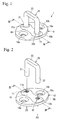
- Fig. 1 is a perspective view of a striker for a vehicular opening/closing member of Embodiment 1.
- Fig. 2 is a perspective view related to the striker for a vehicular opening/closing member of Embodiment 1, showing a state before inserting one end and other end of a rod member substantially in a U-like shape to respective post holes.
- Fig. 3 is a sectional view related to the striker for a vehicular opening/closing member of Embodiment 1, showing a III-III section of Fig. 2 .
- Fig. 4 is a sectional view related to the striker for a vehicular opening/closing member of Embodiment 1, showing a state (state of arranging step) after inserting the one end and the other end of the rod member substantially in the U-like shape to the respective post holes (showing the III-III section of Fig. 2 ).
- Fig. 5 is a sectional view related to the striker for a vehicular opening/closing member of Embodiment 1, showing a state (state of arranging step) immediately before starting a burn-quenching step (showing a section of making V-V section of Fig. 4 upside down).
- Fig. 6 is a sectional view related to the striker for a vehicular opening/closing member of Embodiment 1, showing a state of finishing the burn-caulking step (showing the section of making the V-V section of Fig. 4 upside down).
- Fig. 7 is a sectional view related to the striker for a vehicular opening/closing member of Embodiment 1, showing a VII-VII section of Fig. 1 .
- Fig. 8 is a sectional view of a base plate related to a striker for a vehicular opening/closing member of Embodiment 2, showing grooves turning around inner faces of respective post holes (showing the III-III section of Fig. 2 ).
- Fig. 9 is a sectional view related to a striker for a vehicular opening/closing member of Embodiment 3, showing a rod member having stepped portions at one end and other end thereof (showing the III-III section of Fig. 2 ).
- Fig. 10 is a sectional view related to the striker for a vehicular opening/closing member of Embodiment 3, showing a modified example of a rod member (showing the III-III section of Fig. 2 ).
- Fig. 11 is a perspective view showing a striker for a vehicular opening/closing member of a modified example.
- a striker 1 which is used for a vehicular opening/closing member of Embodiment 1 includes a base plate 10, and a post 20 substantially in a U-like shape projected to a side of a surface 10a of the base plate 10.
- the striker 1 is provided on one side of a vehicular opening/closing member of a door or the like and engaged with a lock apparatus provided on other side of the vehicular opening/closing member and a vehicular main body for maintaining the vehicular opening/closing member to stay to be in a closed state.
- a well-known one of the lock apparatus can be adopted, and therefore, an explanation thereof will be omitted and the striker 1 will be explained in details.
- the striker 1 is manufactured by a manufacturing method including a preparing step, a groove forming step, an arranging step, and a burn-caulking step. The respective steps will be explained successively as follows.
- the base plate 10 and a rod member 29 are prepared.
- the base plate 10 is constituted by pressing a plate member made of steel in a rhombic shape.
- a general hot-rolled steel plate or the like is used as a material of the base plate 10.
- FIG. 2 As shown by Fig. 2 , at the base plate 10 before the post 20 is projected therefrom, two attaching holes 19a and 19b are penetrated at vicinities of two corners opposed to each other of four corners of substantially a rhombus.
- the attaching holes 19a and 19b are utilized when the striker 1 is fastened to be fixed to the vehicular opening/closing member or the vehicular main body.
- the base plate 10 is formed with a projected portion 18 slenderly raised to a side of the surface 10a on a diagonal line connecting other two corners opposed to each other.
- the projected portion 18 is formed by pressing, and therefore, as shown by Fig. 3 , a portion on a side of a back face 10b of the base plate 10 in correspondence with the projected portion 18 is considerably recessed. Both end sides of a long side of the projected portion 18 are penetrated with two post holes 11 and 12.
- the rod member 29 is to constitute the post 20 as shown by Fig. 1 and Fig. 7 at a stage of finishing the method of manufacturing the striker 1.
- the rod member 29 is constituted by folding to bend a round bar made of steel substantially in a U-like shape as shown by Fig. 2 and Fig. 3 .
- As a material of the rod member 29, carbon steel, allow steel or the like is generally used since a strength higher than that of the base plate 10 is requested.
- inner face of the respective post holes 11 and 12 are respectively formed with single streaks of screw grooves 11a and 12a recessed in outer directions of diameters relative to axis centers O1 and 02 of the respective post holes.
- the screw grooves 11a and 12a can easily be formed by using a general screwing tool of a tap or the like.
- inner diameters of the respective screw grooves 11a and 12a are made to be slightly larger than outer diameters of one end 21 and other end 22 to be able to insert the one end 21 and the other end 22 constituting end portions of the rod member 29.
- the one end 21 and the other end 22 of the rod member 29 are brought into a state of being inserted to the respective post holes 11 and 12. Further, as shown by Fig. 5 , by a burn-caulking apparatus 90, the base plate 10 and the rod member 29 are held to stay in the state shown in Fig. 4 by making upside down ( Fig. 5 shows sectional view of making the V-V section of Fig. 4 upside down).
- the burn-caulking apparatus 90 includes a back face side electrode 91 disposed on a side of the back face 10b of the base plate 10 (upper side of paper face of Fig. 5 ) and brought into contact with the one end 21 and the other end 22 of the rod member 29, and a surface side electrode 92 disposed on a side of the surface 10a of the base plate 10 (lower side of paper face of Fig. 5 ) and brought into contact with a bottom portion 23 substantially in the U-like shape of the rod member 29.
- the one end 21 is disposed on a depth side of paper face of other end 22 and the post hole 11 is disposed on depth side of paper face of the post hole 12.
- the burn-caulking apparatus 90 includes a pair of movable electrodes 93a and 93b disposed between the surface 10a of the base plate 10 and the surface side electrode 92 for clamping a middle portion of the rod member 29 from two side directions (left and right direction of paper face of Fig. 5 ).
- the movable electrodes 93a and 93b are constituted to clamp the middle portion of the rod member 29 by being proximate to each other from a state of being remote from each other to left and right sides.
- the burn-caulking apparatus 90 includes rails 94a and 94b made of an insulating material brought into contact with peripheral edges on the side of the surface 10a of the base plate 10, and holding portions 95a and 95b made of an insulating material brought into contact with peripheral edges on the side of the back face 10b of the base plate 10.
- the rails 94a and 94b are supported movably to a lower side by straight moving guides 96a and 96b arranged at side faces of the surface side electrode 92 and coil springs 96c and 96d.
- the holding portions 95a and 95b are supported movably to the upper side by straight moving guides 97a and 97b arranged at side faces of the back face side electrode 91 and coil springs 97c and 97d.
- the base plate 10 and the rod member 29 are restricted to a predetermined relative positional relationship by clamping the base plate 10 by the rails 94a and 94b and the holding portions 95a and 95b.
- portions of the one end 21 and the other end 22 of the rod member 29 disposed between the surface 10a of the base plate 10 and end faces of the movable electrodes 93a and 93b opposed to the base plate 10 are referred to as surface side caulking ball volume portions 21m and 22m.
- the surface side caulking ball volume portion 21m is disposed on depth side of paper face of the surface side caulking ball volume portion 22m.
- portions of the one end 21 and the other 22 of the rod member 29 disposed between the back face 10a of the base plate 10 and end faces of the back face side electrode 91 opposed to the base plate 10 are referred to as back face side caulking ball volume portions 21n and 22n.
- the back face side caulking ball volume portion 21n is disposed on depth side of paper face of the back face side caulking ball volume portion 22n.
- the back face side electrode 91 and the surface side electrode 92 are pressed to be proximate to each other to constitute a predetermined distance therebetween by a press-apparatus, not illustrated, under the state. Then, the relative positional relationship between the back face side electrode 91 and the surface side electrode 92 and the movable electrodes 93a and 93b is displaced from a state shown in Fig. 5 to a state shown in Fig. 6 .
- the coil springs 96c, 96d, 97c, and 97d are compressed and also the rails 94a and 94b and the holding portions 95a and 95b are displaced while clamping the base plate 10. Further, end faces of the rails 94a and 94b opposed to the movable electrodes 93a and 93b are butted to and stopped by the movable electrodes 93a and 93b.
- the surface side caulking ball volume portions 21m and 22m and the back face side caulking ball volume portions 21n and 22n and the middle portions therebetween which are softened are plastically made to flow to deform.
- the surface side caulking ball volume portions 21m and 22m and the back face side caulking ball volume portions 21n and 22n become surface side caulking ball portions 21p and 22p and back face side caulking ball portions 21q and 22q in a shape crashed to a flange-like shape.
- the middle portions of the surface side caulking ball volume portions 21m and 22m and the back face side caulking ball volume portions 21n and 22n are made to flow plastically to be brought into a state of being filled in the screw grooves 11a and 12a.
- the rod member 29 constitutes the post 20 projected from the base plate 10 by burning to caulk the one end 21 and the other end 22. Further, the striker 1 shown in Fig. 1 and Fig. 7 is taken out from the burn-caulking apparatus 90.
- the surface side caulking ball portions 21p and 22p and the back face side caulking ball portions 21q and 22q formed at the one end 21 and the other end 22 clamp surface side edges and back face side edges of the respective post holes 11 and 12.
- portions of the one end 21 and the other end 22 are made to plastically flow to constitute a state of being filled at inside of the screw grooves 11a and 12a formed at the inner faces of the post holes 11 and 12. Therefore, coupling of the post 20 to the base plate 10 becomes further solid. Therefore, rattle is difficult to be brought about in the coupling of the post 20 to the base plate 10 even when the impact in running the vehicle and the impact in opening or closing, the opening/closing member are always received.
- the striker 1 for the vehicular opening/closing member of Embodiment 1 can achieve excellent durability.
- the striker 1 is subjected to a heat treatment or a plating treatment after the burn-caulking step.
- a steel member having a strength comparatively higher than that of a general steel member used in the base plate 10 is used, and therefore, in heating or cooling by the heat treatment or the plating treatment, a thermal stress owing to a difference between linear expansion coefficients is generated between the post and the base plate.
- the striker 1 is made to be difficult to be effected with the influence of heating and cooling since the coupling of the post 20 to the base plate 10 is made to be further solid, and a rate of bringing about rattle can be reduced. As a result, the striker 1 can also realize a high yield.
- the grooves 211a and 212a are formed to be recessed in outer directions of diameters relative to the axis centers O1 and 02 of the respective post holes 11 and 12 and to turn around inner faces of the respective post holes 11 and 12.
- the grooves 211a and 212a can easily be worked by general boring.
- the striker of Embodiment 2 constructing such a constitution can achieve the excellent durability by reason similar to that of the striker 1 of Embodiment 1.
- the grooves 211a and 212a are respectively provided singly, the respective grooves may be formed in plural in a thickness direction of the base plate 10.
- a striker of Embodiment 3 with regard to the rod member 29 of the striker 1 of Embodiment 1, as shown by Fig. 9 , the one end 21 and the other end 22 are changed to include stepped portions 21f and 22f.
- Other constitution is the same as that of the striker 1 of Embodiment 1, and therefore, the same notations are attached to constitutions the same as those of Embodiment 1 and an explanation thereof will be omitted.
- the one end 21 and the other end 22 of the rod member 29 include the stepped portions 21f and 22f in a flange-like shape.
- outer diameters of which are made to be sufficiently larger than diameters of valleys of the screw grooves 11a and 12a such that the stepped portions 21f and 22f are brought into contact with peripheral edges of the respective post holes 11 and 12 on the side of the surface 10a of the base plate 10 when inserted to the respective post holes 11 and 12.
- the stepped portions 21f and 22f are previously formed, and therefore, caulking ball portions larger than the surface side caulking ball portions 21p and 22p of the striker 1 of Embodiment 1 are formed. Therefore, according to the striker of Embodiment 3, the one end 21 and the other end 22 can further firmly clamp surface side edges and back face side edges of the respective post holes 11 and 12, and therefore, operation and effect of the invention can further firmly be achieved.
- the rod member 29 may be constituted by a shape in which large diameter sides of the stepped portions 21f and 22f are continued to the bottom portion 23 substantially in the U-like shape while maintaining outer diameters thereof.
- working of the rod member 29 in a prestage of folding to bend the rod member 29 substantially in the U-like shape can be simplified more than the case shown in Fig. 9 (only both ends of a bold rob member may be made to be machined to a small diameter).
- the striker of Embodiment 3 it is comparatively easy to adopt cold forging of caulking the one end 21 and the other end 22 of the rod member 29 without heating the rod member 29. That is, the stepped portions 21f and 22f in correspondence with the surface side caulking ball portions 21p and 22p of the striker 1 of Embodiment 1 are previously formed, and therefore, when the one end 21 and the other end 22 are caulked by cold forging to form the back face side caulking ball portions 21q and 22q and the one end 21 and the other end 22 are made to plastically flow in the screw grooves 11a and 12a, operation and effect of the invention can be achieved.
- Embodiments 1 through 3 Although an explanation has been given of the invention based on Embodiments 1 through 3 as described above, the invention is not limited to Embodiments 1 through 3 mentioned above but naturally applicable by being changed in the range not deviated from the gist.
- the burn-caulking apparatus 90 is not limited to the one shown in Fig. 5 and Fig. 6 but may be constituted by making upside down or constituent elements and operation thereof may differ.
- the method of manufacturing the striker 1 may include a step other than the preparing step, the groove forming step, the arranging step and the burn-caulking step described above.
- the invention is applicable to a striker 100 including a base plate 110 made of a steel penetrated with one post hole and a post 120 projected from the base plate 110 by caulking an end portion of a rod member made of a steel in a state of being inserted to the post hole.
- the invention can be utilized in a lock apparatus of a vehicular opening/closing member.
Landscapes
- Engineering & Computer Science (AREA)
- Mechanical Engineering (AREA)
- Lock And Its Accessories (AREA)
- Heat Treatment Of Articles (AREA)
Applications Claiming Priority (1)
| Application Number | Priority Date | Filing Date | Title |
|---|---|---|---|
| JP2007246345A JP5015709B2 (ja) | 2007-09-24 | 2007-09-24 | 車両用開閉体のストライカ及びその製造方法 |
Publications (3)
| Publication Number | Publication Date |
|---|---|
| EP2039855A2 true EP2039855A2 (de) | 2009-03-25 |
| EP2039855A3 EP2039855A3 (de) | 2009-10-14 |
| EP2039855B1 EP2039855B1 (de) | 2011-12-14 |
Family
ID=40261962
Family Applications (1)
| Application Number | Title | Priority Date | Filing Date |
|---|---|---|---|
| EP20080014514 Ceased EP2039855B1 (de) | 2007-09-24 | 2008-08-14 | Schlagbolzen für ein Fahrzeugöffnungs- bzw. schließungsglied und Herstellungsverfahren |
Country Status (4)
| Country | Link |
|---|---|
| US (1) | US20090079208A1 (de) |
| EP (1) | EP2039855B1 (de) |
| JP (1) | JP5015709B2 (de) |
| CN (1) | CN101439655A (de) |
Cited By (1)
| Publication number | Priority date | Publication date | Assignee | Title |
|---|---|---|---|---|
| DE102009051121A1 (de) * | 2009-10-28 | 2011-05-05 | Audi Ag | Schlossbügelanordnung eines Fahrzeugschlosses, inbesondere für eine Fronthaube |
Families Citing this family (15)
| Publication number | Priority date | Publication date | Assignee | Title |
|---|---|---|---|---|
| US8439317B2 (en) * | 2009-02-27 | 2013-05-14 | Franklin Fastener Company | Grommeted clamp assembly |
| JP5285524B2 (ja) | 2009-07-22 | 2013-09-11 | 株式会社アンセイ | 車両用ドアロック装置 |
| JP5373535B2 (ja) * | 2009-10-07 | 2013-12-18 | テイ・エス テック株式会社 | ロック装置およびロック装置の組立方法 |
| JP5725154B2 (ja) | 2011-03-16 | 2015-05-27 | 株式会社アンセイ | 車両用ドアロック装置 |
| JP5141795B2 (ja) * | 2011-06-20 | 2013-02-13 | 株式会社豊田自動織機 | 車両用バッテリユニット装着装置 |
| JP5382374B2 (ja) * | 2011-06-22 | 2014-01-08 | アイシン精機株式会社 | 車両用ドアハンドル |
| WO2013046317A1 (ja) | 2011-09-27 | 2013-04-04 | 株式会社アンセイ | 車両用ドアロック装置 |
| DE102016110688B4 (de) * | 2016-06-10 | 2024-07-18 | Kiekert Aktiengesellschaft | Verfahren zur Herstellung einer Schließbügelanordnung und zugehörige Schließbügelanordnung |
| US10407964B2 (en) * | 2017-04-19 | 2019-09-10 | Nissan North America, Inc. | Door striker assembly |
| CN111434875A (zh) * | 2019-01-15 | 2020-07-21 | 北京宝沃汽车有限公司 | 发动机盖锁扣总成和车辆 |
| CN111434876A (zh) * | 2019-01-15 | 2020-07-21 | 北京宝沃汽车有限公司 | 发动机盖锁扣总成和车辆 |
| EP3942132A4 (de) * | 2019-03-22 | 2023-01-04 | Amanda Manufacturing, LLC | Hochfester türanschlag und verfahren zur herstellung |
| US11608663B2 (en) * | 2019-05-10 | 2023-03-21 | Kawasaki Motors, Ltd. | Door striker attaching structure and utility vehicle including the same |
| CN115815435A (zh) * | 2022-10-15 | 2023-03-21 | 广东顺德朗途精密制造有限公司 | 一种开关类的银触点与铜柱的结合铆接工艺 |
| DE102023123600A1 (de) * | 2023-07-05 | 2025-01-09 | Magna BÖCO GmbH | Verschlussvorrichtung |
Citations (1)
| Publication number | Priority date | Publication date | Assignee | Title |
|---|---|---|---|---|
| JPH0825965A (ja) | 1994-07-14 | 1996-01-30 | Mitsui Mining & Smelting Co Ltd | 車両扉用ストライカー装置およびその製造方法 |
Family Cites Families (11)
| Publication number | Priority date | Publication date | Assignee | Title |
|---|---|---|---|---|
| US3591225A (en) * | 1970-02-24 | 1971-07-06 | Atwood Vacuum Machine Co | Striker for use with a vehicle latch |
| JPS4824117U (de) * | 1971-07-29 | 1973-03-20 | ||
| JPS5679562U (de) * | 1979-11-22 | 1981-06-27 | ||
| JPS582282U (ja) * | 1981-06-29 | 1983-01-08 | 株式会社大井製作所 | ドアロック用ストライカ |
| JPH0639013Y2 (ja) * | 1987-05-29 | 1994-10-12 | 株式会社大井製作所 | 車両用ストライカ |
| JPH0860905A (ja) * | 1994-08-17 | 1996-03-05 | Aoyama Seisakusho:Kk | ドアロックストライカー及びその製造方法 |
| DE29713784U1 (de) * | 1997-08-02 | 1997-11-20 | GRIWE Innovative Umformtechnik GmbH, 56457 Westerburg | Haltevorrichtung |
| JPH11350815A (ja) * | 1998-06-09 | 1999-12-21 | Mitsui Mining & Smelting Co Ltd | 車両用ストライカ |
| JP2002201830A (ja) * | 2000-12-30 | 2002-07-19 | Mitsui Mining & Smelting Co Ltd | 車両ドアラッチ装置のストライカとその製造方法 |
| US20070001468A1 (en) * | 2004-03-29 | 2007-01-04 | Burton John E | Bent wire door striker |
| US7159289B1 (en) * | 2004-05-20 | 2007-01-09 | Ankara Industries, Inc. | Fastener forming apparatus and method for making a fastener of metal |
-
2007
- 2007-09-24 JP JP2007246345A patent/JP5015709B2/ja active Active
-
2008
- 2008-08-12 US US12/190,120 patent/US20090079208A1/en not_active Abandoned
- 2008-08-14 EP EP20080014514 patent/EP2039855B1/de not_active Ceased
- 2008-08-21 CN CNA2008101308796A patent/CN101439655A/zh active Pending
Patent Citations (1)
| Publication number | Priority date | Publication date | Assignee | Title |
|---|---|---|---|---|
| JPH0825965A (ja) | 1994-07-14 | 1996-01-30 | Mitsui Mining & Smelting Co Ltd | 車両扉用ストライカー装置およびその製造方法 |
Cited By (2)
| Publication number | Priority date | Publication date | Assignee | Title |
|---|---|---|---|---|
| DE102009051121A1 (de) * | 2009-10-28 | 2011-05-05 | Audi Ag | Schlossbügelanordnung eines Fahrzeugschlosses, inbesondere für eine Fronthaube |
| DE102009051121B4 (de) * | 2009-10-28 | 2012-01-19 | Audi Ag | Schlossbügelanordnung eines Fahrzeugschlosses, inbesondere für eine Fronthaube |
Also Published As
| Publication number | Publication date |
|---|---|
| JP2009074324A (ja) | 2009-04-09 |
| US20090079208A1 (en) | 2009-03-26 |
| EP2039855B1 (de) | 2011-12-14 |
| EP2039855A3 (de) | 2009-10-14 |
| CN101439655A (zh) | 2009-05-27 |
| JP5015709B2 (ja) | 2012-08-29 |
Similar Documents
| Publication | Publication Date | Title |
|---|---|---|
| EP2039855A2 (de) | Schlagbolzen für ein Fahrzeugöffnungs- bzw. schließungsglied und Herstellungsverfahren | |
| EP1316492B1 (de) | Hohle Zahnstange für Fahrzeuglenkung und Verfahran zu ihrer Herstellung | |
| US5054195A (en) | Process for the production of a valve | |
| EP0619419B1 (de) | Ultraleichtes Ventil für Brennkraftmaschine | |
| US9919356B2 (en) | Punch-riveting die | |
| US20140356101A1 (en) | Weld Rivet Joint | |
| US7748743B2 (en) | Structural or chassis component for a motor vehicle, and method of making such a structural or chassis component | |
| CN1938120A (zh) | 在一个或多个连接点对两个或多个型材件或金属板进行机械连接和压焊的方法 | |
| WO2008109649A2 (en) | Fracture resistant friction stir welding tool | |
| DE10049660A1 (de) | Verfahren zum Herstellen lokal verstärkter Blechumformteile | |
| US7955035B2 (en) | Rivet | |
| CN102202812A (zh) | 铝热交换器集流箱的成型方法 | |
| JP2007505789A (ja) | 複合ステアリングラック | |
| CN114502453A (zh) | 车辆底板及相应的生产方法 | |
| US20080012302A1 (en) | Fitting and method for manufacturing a fitting | |
| JP2008055483A (ja) | 突合せ接合方法、メカニカルクリンチ装置、接合ロッドおよびシリンダ装置の製造方法 | |
| US6938816B2 (en) | Methods of manufacturing diffusion bonded products and products manufactured by such methods | |
| Golovashchenko | Electromagnetic forming and joining for automotive applications | |
| JP2010535998A (ja) | 駆動クラッチ用クラッチリンクおよび製造方法 | |
| GB2330096A (en) | A process for producing a tubular structural element | |
| US20050091825A1 (en) | Method of manufacturing hollow structural elements | |
| JP2009544887A (ja) | シャフト−ハブ接続を形成するための方法及び装置 | |
| EP1631402B1 (de) | Verfahren zur herstellung hohler bauelemente | |
| US7617584B1 (en) | Method of making a fastener of metal | |
| EP1795280B1 (de) | Vorrichtung und Verfahren zur Herstellung eines Gehäuseteils mit Flansch |
Legal Events
| Date | Code | Title | Description |
|---|---|---|---|
| PUAI | Public reference made under article 153(3) epc to a published international application that has entered the european phase |
Free format text: ORIGINAL CODE: 0009012 |
|
| AK | Designated contracting states |
Kind code of ref document: A2 Designated state(s): AT BE BG CH CY CZ DE DK EE ES FI FR GB GR HR HU IE IS IT LI LT LU LV MC MT NL NO PL PT RO SE SI SK TR |
|
| AX | Request for extension of the european patent |
Extension state: AL BA MK RS |
|
| PUAL | Search report despatched |
Free format text: ORIGINAL CODE: 0009013 |
|
| AK | Designated contracting states |
Kind code of ref document: A3 Designated state(s): AT BE BG CH CY CZ DE DK EE ES FI FR GB GR HR HU IE IS IT LI LT LU LV MC MT NL NO PL PT RO SE SI SK TR |
|
| AX | Request for extension of the european patent |
Extension state: AL BA MK RS |
|
| 17P | Request for examination filed |
Effective date: 20091209 |
|
| 17Q | First examination report despatched |
Effective date: 20100113 |
|
| AKX | Designation fees paid |
Designated state(s): DE |
|
| AXX | Extension fees paid |
Extension state: BA Payment date: 20100414 Extension state: AL Payment date: 20100414 Extension state: RS Payment date: 20100414 Extension state: MK Payment date: 20100414 |
|
| GRAP | Despatch of communication of intention to grant a patent |
Free format text: ORIGINAL CODE: EPIDOSNIGR1 |
|
| GRAS | Grant fee paid |
Free format text: ORIGINAL CODE: EPIDOSNIGR3 |
|
| GRAA | (expected) grant |
Free format text: ORIGINAL CODE: 0009210 |
|
| AK | Designated contracting states |
Kind code of ref document: B1 Designated state(s): DE |
|
| REG | Reference to a national code |
Ref country code: DE Ref legal event code: R096 Ref document number: 602008011902 Country of ref document: DE Effective date: 20120209 |
|
| PLBE | No opposition filed within time limit |
Free format text: ORIGINAL CODE: 0009261 |
|
| STAA | Information on the status of an ep patent application or granted ep patent |
Free format text: STATUS: NO OPPOSITION FILED WITHIN TIME LIMIT |
|
| 26N | No opposition filed |
Effective date: 20120917 |
|
| REG | Reference to a national code |
Ref country code: DE Ref legal event code: R097 Ref document number: 602008011902 Country of ref document: DE Effective date: 20120917 |
|
| PGFP | Annual fee paid to national office [announced via postgrant information from national office to epo] |
Ref country code: DE Payment date: 20210809 Year of fee payment: 14 |
|
| REG | Reference to a national code |
Ref country code: DE Ref legal event code: R119 Ref document number: 602008011902 Country of ref document: DE |
|
| PG25 | Lapsed in a contracting state [announced via postgrant information from national office to epo] |
Ref country code: DE Free format text: LAPSE BECAUSE OF NON-PAYMENT OF DUE FEES Effective date: 20230301 |