EP2042076B1 - Structure orientable du type catheter ou endoscope - Google Patents
Structure orientable du type catheter ou endoscope Download PDFInfo
- Publication number
- EP2042076B1 EP2042076B1 EP08163918.9A EP08163918A EP2042076B1 EP 2042076 B1 EP2042076 B1 EP 2042076B1 EP 08163918 A EP08163918 A EP 08163918A EP 2042076 B1 EP2042076 B1 EP 2042076B1
- Authority
- EP
- European Patent Office
- Prior art keywords
- structure according
- actuator
- longitudinal body
- longitudinal
- catheter
- Prior art date
- Legal status (The legal status is an assumption and is not a legal conclusion. Google has not performed a legal analysis and makes no representation as to the accuracy of the status listed.)
- Active
Links
Images


Classifications
-
- A—HUMAN NECESSITIES
- A61—MEDICAL OR VETERINARY SCIENCE; HYGIENE
- A61B—DIAGNOSIS; SURGERY; IDENTIFICATION
- A61B1/00—Instruments for performing medical examinations of the interior of cavities or tubes of the body by visual or photographical inspection, e.g. endoscopes; Illuminating arrangements therefor
- A61B1/005—Flexible endoscopes
- A61B1/0051—Flexible endoscopes with controlled bending of insertion part
- A61B1/0055—Constructional details of insertion parts, e.g. vertebral elements
-
- A—HUMAN NECESSITIES
- A61—MEDICAL OR VETERINARY SCIENCE; HYGIENE
- A61B—DIAGNOSIS; SURGERY; IDENTIFICATION
- A61B1/00—Instruments for performing medical examinations of the interior of cavities or tubes of the body by visual or photographical inspection, e.g. endoscopes; Illuminating arrangements therefor
- A61B1/005—Flexible endoscopes
- A61B1/0058—Flexible endoscopes using shape-memory elements
-
- A—HUMAN NECESSITIES
- A61—MEDICAL OR VETERINARY SCIENCE; HYGIENE
- A61M—DEVICES FOR INTRODUCING MEDIA INTO, OR ONTO, THE BODY; DEVICES FOR TRANSDUCING BODY MEDIA OR FOR TAKING MEDIA FROM THE BODY; DEVICES FOR PRODUCING OR ENDING SLEEP OR STUPOR
- A61M25/00—Catheters; Hollow probes
- A61M25/0043—Catheters; Hollow probes characterised by structural features
- A61M25/0054—Catheters; Hollow probes characterised by structural features with regions for increasing flexibility
-
- A—HUMAN NECESSITIES
- A61—MEDICAL OR VETERINARY SCIENCE; HYGIENE
- A61M—DEVICES FOR INTRODUCING MEDIA INTO, OR ONTO, THE BODY; DEVICES FOR TRANSDUCING BODY MEDIA OR FOR TAKING MEDIA FROM THE BODY; DEVICES FOR PRODUCING OR ENDING SLEEP OR STUPOR
- A61M25/00—Catheters; Hollow probes
- A61M25/01—Introducing, guiding, advancing, emplacing or holding catheters
- A61M25/0105—Steering means as part of the catheter or advancing means; Markers for positioning
- A61M25/0133—Tip steering devices
- A61M25/0158—Tip steering devices with magnetic or electrical means, e.g. by using piezo materials, electroactive polymers, magnetic materials or by heating of shape memory materials
-
- G—PHYSICS
- G01—MEASURING; TESTING
- G01M—TESTING STATIC OR DYNAMIC BALANCE OF MACHINES OR STRUCTURES; TESTING OF STRUCTURES OR APPARATUS, NOT OTHERWISE PROVIDED FOR
- G01M13/00—Testing of machine parts
- G01M13/02—Gearings; Transmission mechanisms
- G01M13/028—Acoustic or vibration analysis
-
- G—PHYSICS
- G01—MEASURING; TESTING
- G01N—INVESTIGATING OR ANALYSING MATERIALS BY DETERMINING THEIR CHEMICAL OR PHYSICAL PROPERTIES
- G01N27/00—Investigating or analysing materials by the use of electric, electrochemical, or magnetic means
- G01N27/72—Investigating or analysing materials by the use of electric, electrochemical, or magnetic means by investigating magnetic variables
- G01N27/82—Investigating or analysing materials by the use of electric, electrochemical, or magnetic means by investigating magnetic variables for investigating the presence of flaws
- G01N27/90—Investigating or analysing materials by the use of electric, electrochemical, or magnetic means by investigating magnetic variables for investigating the presence of flaws using eddy currents
- G01N27/904—Investigating or analysing materials by the use of electric, electrochemical, or magnetic means by investigating magnetic variables for investigating the presence of flaws using eddy currents with two or more sensors
-
- G—PHYSICS
- G01—MEASURING; TESTING
- G01N—INVESTIGATING OR ANALYSING MATERIALS BY DETERMINING THEIR CHEMICAL OR PHYSICAL PROPERTIES
- G01N29/00—Investigating or analysing materials by the use of ultrasonic, sonic or infrasonic waves; Visualisation of the interior of objects by transmitting ultrasonic or sonic waves through the object
- G01N29/04—Analysing solids
- G01N29/043—Analysing solids in the interior, e.g. by shear waves
-
- G—PHYSICS
- G01—MEASURING; TESTING
- G01N—INVESTIGATING OR ANALYSING MATERIALS BY DETERMINING THEIR CHEMICAL OR PHYSICAL PROPERTIES
- G01N2291/00—Indexing codes associated with group G01N29/00
- G01N2291/26—Scanned objects
- G01N2291/263—Surfaces
- G01N2291/2636—Surfaces cylindrical from inside
-
- G—PHYSICS
- G01—MEASURING; TESTING
- G01N—INVESTIGATING OR ANALYSING MATERIALS BY DETERMINING THEIR CHEMICAL OR PHYSICAL PROPERTIES
- G01N2291/00—Indexing codes associated with group G01N29/00
- G01N2291/26—Scanned objects
- G01N2291/269—Various geometry objects
- G01N2291/2693—Rotor or turbine parts
-
- G—PHYSICS
- G02—OPTICS
- G02B—OPTICAL ELEMENTS, SYSTEMS OR APPARATUS
- G02B23/00—Telescopes, e.g. binoculars; Periscopes; Instruments for viewing the inside of hollow bodies; Viewfinders; Optical aiming or sighting devices
- G02B23/24—Instruments or systems for viewing the inside of hollow bodies, e.g. fibrescopes
- G02B23/2476—Non-optical details, e.g. housings, mountings, supports
Definitions
- the present invention relates to a steerable structure of the catheter or endoscope type intended for the internal exploration of a three-dimensional system, such as for example a turbomachine.
- Current catheters or endoscopes are in the form of long rigid or elastically deformable tubes having an end orientable relative to their longitudinal axis to select a particular angle of view and facilitate the progression of the catheter or endoscope.
- actuators in the form of wire shape memory material, which are connected to means of heating by Joule effect. Indeed, these actuators are reduced in length by the effect of an increase in temperature, which induces a change in the curvature of the catheter or the endoscope in the areas where the actuators are located.
- the control of the various actuators distributed along the length of the endoscope or catheter makes it possible to position its distal end in a three-dimensional space.
- the diameter of the distal end is generally of the order of 5 to 8 mm in order to avoid sagging under the effect of gravity. This too large end diameter makes it impossible to explore certain critical areas.
- Current devices also suffer from limitations due mainly to lack of mobility and maneuverability in geometrically complex or cramped spaces. Indeed, during the contraction of an actuator, the locally caused bending of the device has a substantially constant radius of curvature since the rigidity of the device is substantially constant over its entire length. Therefore, it is not possible to inspect complex three-dimensional cavities having passages of reduced dimensions and requiring different successive orientation changes.
- the document EP0199870 discloses a steerable structure for scanning organs of the human body, comprising a longitudinal body carrying shape memory material elements that can slide relative to the longitudinal body when one of the shape memory material elements is heated by Joule effect to be brought into a predetermined configuration.
- the document EP0279316 discloses a mechanism for bending a longitudinal body, comprising an elongated body having a flexible portion having a longitudinal variation of its elastic modulus.
- An optical fiber extends within the longitudinal body and is in contact with a shape memory material arranged within the flexible portion.
- the present invention relates to a structure of the type described above, which avoids the aforementioned drawbacks of the prior art simply, efficiently and economically, and provides access to parts of a system inaccessible by the known means.
- a steerable structure of the catheter or endoscope type intended for the observation or the treatment of a masked object, accessible through a narrow and / or sinuous passage, comprising an elastically deformable longitudinal body comprising at least one actuator of shape memory type material longitudinally integrated with the longitudinal body and Joule effect heating means for longitudinally contracting the actuator to cause bending of the longitudinal body, characterized in that the actuator extends over at least a variable rigidity portion of the longitudinal body.
- variable rigidity of the longitudinal body thus allows a weak deflection in the areas where the rigidity is important and a greater deflection in the areas of lower stiffness which allows to obtain a profile of curvature of the structure with variable radii of curvature along the structure.
- variable rigidity part of the structure comprises at least one material thickness, which makes it possible to increase the rigidity in this zone with respect to the zones without extra thickness, and to create a radius profile. of variable curvature during the contraction of the actuator.
- variable stiffness of the longitudinal body can be determined to achieve, by contraction of the actuator, a modification and / or an inversion of the longitudinal or transverse curvature of the longitudinal body.
- the longitudinal body and the extra thickness may be made of similar materials such as for example one or polymers.
- the longitudinal body comprises at least one tube whose diameter is for example of the order of 2 to 6 mm, and the actuator extends longitudinally on an inner or outer wall of the tube, on at least part of the length of it
- the longitudinal body comprises an elongated cross-sectional blade and two parallel actuators are incorporated in the blade and extend along a longitudinal face of the blade.
- the blade can have a thickness of about 1 to 2 mm for a width of about 1 cm and a length of about 5 to 10 cm.
- the areas to be explored have a strong axial symmetry. Therefore, the passages that the structure must take are often sections of low height but wide so that one can consider the use of structures of elongated cross section, for example rectangular.
- the use of such a form of structure makes it possible to pass additional tools such as clamps, optical fibers, various connections, through channels extending longitudinally in the structure.
- an elongated cross-section structure is more resistant to transverse stress applied in the large dimension of this section.
- the number of actuators can also be increased because of the larger space available in the cross section, which improves the control of the curvature given to the structure.
- the actuator used to bend the endoscope may be a nickel-titanium alloy wire, the diameter of which is, for example, from about 0.1 to 0.5 millimeters.
- the structure is of the telescopic type and comprises a plurality of elastically deformable bodies provided with actuators and engaged in each other.
- this structure comprises at its distal end resilient means exerting a longitudinal thrust force and connected to a head provided with non-destructive control means.
- the distal end of the structure is not rigidly connected to the elastic body, but is attached thereto by thrust means which make it possible to ensure permanent contact between the surface of the part to be studied and the non-destructive control means carried by the head of the structure.
- the thrust means may be springs, at least some of which are of shape memory contractile material and are connected to heating means by Joule effect.
- springs of contractile material makes it possible to vary their stiffness to better adjust the pressure exerted on the surface of the examined part.
- the non-destructive testing means may be eddy current probes or ultrasonic probes, for example.
- a transverse dimension of the structure may vary between 8 mm at its proximal end and about 1 mm at its distal end. Furthermore, this structure may comprise means for attachment or support to surrounding fixed elements.
- the progression of the structure within a system, achieved by successive interlocking of several individual structures orientable can lead to a displacement of its distal end by deflection of the structure.
- the attachment or support means then allow precise positioning on intermediate fixed elements in order to limit the effect of gravity on the structure and improve the control of the positioning and orientation of its end. .
- This also allows for structures of the catheter or endoscope type longer and thinner.
- the power supply means of the actuators, causing them to be heated, can be controlled automatically, which makes it possible, in the case of a system of known geometry, to carry out the movement of the structure inside the automatically explored system. and thus to overcome the many difficulties inherent in the continuous control of actuators based on contractile material.
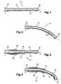
- FIG 1 is a schematic view of a steerable structure 10 of the catheter or endoscope type according to the prior art, comprising a tubular flexible body 12 having a longitudinal axis 14 and comprising an actuator 16 made of a contractile material, for example of the shape memory type ( hereinafter referred to as AMF) arranged along the tubular structure and inside thereof.
- This actuator 16 is in the form of a wire connected to power supply means (not shown).
- the steerable structure 10 includes a fixed proximal end 18 and a steerable distal end 20.
- the Joule heating of the AMF wire induces a rearrangement of the atoms constituting the wire (when the activation temperature is reached), leading to a contraction (with a response time of less than one second) and thus a decrease in its length.
- the wire 16 attached to a wall of the tube 12 induces a distortion of its distal end 20 in a direction perpendicular to the axis 14 ( figure 2 ).
- the structure 10 thus bent adopts a circular arc profile of substantially constant radius of curvature insofar as the rigidity along the tube 12 is substantially constant.
- Such a catheter allows angular orientation of its distal end 20 only a few degrees about the longitudinal axis 14 if it is necessary to limit the relative lateral displacement between the two ends 18, 20 of the catheter.
- a change in the larger angular orientation results in an increase in the lateral displacement of the distal end of the catheter.
- Such a structure can therefore only be used in systems where the passages are narrow and with small angular changes or in systems having sufficiently large passages to allow a large lateral deflection, which represents a strong limitation to the exploration internal systems very complex and cramped as they exist in aeronautics, for example.
- Stopping the Joule heating of the wire leads to a cooling of the wire 16 and a return to the longitudinal initial state of the structure 10 by elastic effect.
- the structure 21 comprises a flexible body 22 comprising at least a variable rigidity portion on which the wire 16 MFA extends.
- This variation of rigidity is obtained by arranging or forming thicknesses of material on the outer surface of the tube 22.
- a first thickness of material 24 is disposed around the tube 22 and a second thickening 26 of axial dimension more small that the first is disposed around the first extra thickness 24.
- the flexible body has its proximal end 18 towards its distal end 20 a decreasing rigidity.
- the tube is bent according to a variable radius of curvature ( figure 4 ). Indeed, the tube bends weakly in its part having a high rigidity and curve more importantly in the lower stiffness zone. It is also noted that the lateral deflection is lower and therefore the size reduced compared to the prior art for the same angular orientation of the distal end 20.
- the diameter of the wire 16 is of the order of 0.5 to 0.1 millimeters and its longitudinal contraction, obtained by heating Joule effect (produced by an electric power of about 0.5 watts), is order of 5 to 6% of its length.
- the tube 22 has a diameter of the order of 2 to 6 millimeters and is made of polymer material, like the existing medical catheters. Adjusting the intensity of the electric current passing through the actuators also makes it possible to adjust the contraction and thus the curvature of the body 22.
- the passages taken by the endoscopes or catheters for the inspection of machines are often in the form of narrow slots, in particular in axially symmetric systems as in turbomachines. It is therefore not necessary that the catheter is tubular and it can adopt another form.
- the invention can therefore also be applied to a longitudinal flexible body 28 of elongated cross section such as that represented in FIG. figure 5 where the body 28 is in the form of a blade of substantially rectangular section.
- the catheter 27 comprises a flexible body 28 having layers of material arranged in excess thickness in order to modify the rigidity of the blade in the longitudinal direction. These additional layers of material are formed of lamellae of equally rectangular section.
- the structure here comprises four layers of material or slats added, of width identical to that of the blade 28.
- a first blade 30 is positioned on one face of the body 28 while another blade 32 of the same length as the first is positioned on the opposite face, at the other end of the longitudinal body 28.
- Two other strips 34, 36 of equal length are respectively disposed on each of the first two strips 30, 32 and are of shorter lengths than the strips 30 and 32.
- Two parallel son 38 contractile or AMF are incorporated in the blade 28 and extend parallel to its longitudinal faces in its median plane.
- the structure of the figure 7 represents a "bowl" shape.
- a shape can be obtained by adding a slat 40 in excess of the flexible body 28 at each of its ends, these two slats being disposed on the same face while the opposite face comprises two slats 42 aligned along the body 28 and arranged between end plates 40.
- This type of structure can be used to stabilize an endoscope or catheter by pressing on surrounding fixed elements 44, which limits the effects of gravity on the entire structure and makes it possible to use longer and thinner catheters than if they consisted of self-supporting structures only.
- the attachment or support means may also be particularly useful during a non-destructive testing operation, described later, which requires a stable position of the distal end of the catheter.
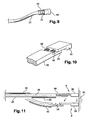
- the "hook" shaped structure of the figure 8 can be obtained using three layers of material 46, 48, 50 of different lengths stacked on each other on the same face of the blade 28.
- the proximal end 18 of the longitudinal body 28 undergoes only a slight deflection while the majority of the deflection is concentrated at its distal end 20, which allows to obtain an angular displacement of the distal end 20 which can be greater than 90 ° while maintaining a low lateral deflection.
- catheters or endoscopes may comprise elastic means exerting longitudinal thrust force on a head provided with non-destructive control means.
- These elastic means comprise for example helical springs.
- a helical spring 52 is wound around the distal end 20 of the flexible body 22 and is supported on a flange of the longitudinal body 22, the other end of the spring 52 being supported on the bottom of a shaped element cap 54 surrounding the spring 52.
- the flexible body 28 ( figure 10 ) is of elongated cross section, for example rectangular
- its distal end 20 may comprise a rectangular recess on which is guided a head 56 of complementary shape.
- the head 56 is connected to the longitudinal body 28 by two springs 58 arranged in parallel.
- the springs 52, 58 make it possible to keep the head 54, 56 in contact with the surface for the time necessary for examination of the coin by the means non-destructive testing.
- the springs 52, 58 may be made of contractile material or shape memory in the case where the control of the stiffness of the spring or the force applied is interesting. Such springs can also make it possible to control with great precision the distance between the end of the head and the surface.
- the figure 11 represents two positions of a catheter or endoscope according to the invention, one (A) corresponding to the initial state before elastic deformation and the other (B) corresponding to the state after elastic deformation.
- the catheter is of the elongate cross-sectional type and comprises two material layers 60, 62 disposed on opposite sides of the ends of the flexible body 28 and two AMF wires 38 as described for the figure 5 and one or more springs 58 connecting the head 56 to the elastic body 28, the head 56 being in contact with a surface of a part of interest 64.
- the catheter adopts an "S" shape according to the principle described above, which allows a shift of the distal end perpendicular to the longitudinal axis without changing its orientation.
- the spring or springs 58 serve to keep the head in permanent contact with the surface of the workpiece 64.
- Non-destructive testing means such as eddy current probes or ultrasonic probes may be particularly useful for detecting surface cracks.
- the figure 12 represents a stage of a turbomachine comprising an alternation of moving blades 66 and fixed blades 68 surrounded by an outer casing 70.
- the blades 68 have their inner end radially aligned with wipers 72 mounted on a portion of the rotor 74. These wipers 72 make it possible to avoid any air circulation between a fixed blade 68 and the rotor 74. It is therefore important to be able to check the state of wear of these parts to avoid any reduction in the performance of the turbomachine.
- the catheters or endoscopes used for this purpose are of the telescopic type that is to say that they consist of a plurality of bodies elastically deformable with contractile actuators and engaged in each other.
- a catheter according to the invention makes it possible to control these wipers 72 in a simple and fast manner.
- a first rigid tubular body 76 is introduced into an endoscopic orifice 78 opening between two adjacent fixed vanes 68 and a second flexible body 80 of shaped form.
- S is introduced inside the first body.
- the heating means of the actuators allow this catheter 80 to be shaped in the space between two fixed blades 68.
- a third flexible body 82 having a single direction of curvature is introduced inside the first two catheters 78, 80 and is controlled so that its head can be placed in contact with a wiper 72.
- the rotor of the turbomachine is then rotated which allows through the non-destructive testing means placed at the head of the catheter 82 to examine the surface condition of the part over 360 °.
- the head can be connected to a spring as previously described to ensure permanent contact.
- the total length of the catheter is relatively large, for example about 60 centimeters, and may induce misalignment of its distal end.
- the vanes 68 may be used as fulcrum and attachment points of the intermediate catheter 80 using elements such as deployable tongs or trellis to stabilize the telescopic catheter assembly.
- variable rigidity configuration makes it possible to maneuver the catheter to inaccessible areas that require it to travel in small passages.
- the elongate cross section catheters may be solid as shown in the drawings or hollow. In the case of solid telescopic catheters, it is possible to provide guiding means such as rails situated along the longitudinal bodies.
- the invention is also not limited to the type of AMF actuators used in the embodiments shown in the drawings, namely single-effect AMF wires, that is to say whose mode of action is limited to one direction. It is also possible to use other actuators such as AMF blades, possibly having two memorized positions in order to obtain a quicker return to the orientable structure. It is also possible to produce a return to the initial state faster to dispose of AMF son along the elastic body and in the opposite position, and to actuate successively.
- the invention described above is particularly useful in the field of three-dimensional exploration of complex industrial devices, it can also be used in other fields and in particular in the biomedical field where the maneuverability of catheters is a key point of a successful anatomical and functional exploration.
- the invention also relates to a catheter or endoscope comprising automatic control means connected to each of the contractile actuators.
- This is particularly interesting in the case of perfectly known geometry systems. By using the system planes, it is possible to precisely define the path to follow and the shape to be given to the structure, and to program the control of the actuators from the introduction of the structure into an endoscopic orifice.
- the invention authorizes the manufacture of dedicated catheters for the exploration of systems of a given type and non-destructive testing of a single type of parts.
- the contractile material may be for example an alloy of titanium and nickel.
- the elastic body and the layers of material may be made of spring steel or a polymer such as polyethyletherketone, epoxy, polyethylene or polyurethane depending on the desired rigidity.
- the invention is not limited to catheters of rectangular or circular section and also applies to catheters of any cross section, for example oval, square, triangular, etc.
Landscapes
- Health & Medical Sciences (AREA)
- Life Sciences & Earth Sciences (AREA)
- Physics & Mathematics (AREA)
- General Health & Medical Sciences (AREA)
- Animal Behavior & Ethology (AREA)
- Biophysics (AREA)
- Veterinary Medicine (AREA)
- Public Health (AREA)
- Pathology (AREA)
- Engineering & Computer Science (AREA)
- Biomedical Technology (AREA)
- Heart & Thoracic Surgery (AREA)
- Surgery (AREA)
- Chemical & Material Sciences (AREA)
- General Physics & Mathematics (AREA)
- Analytical Chemistry (AREA)
- Biochemistry (AREA)
- Immunology (AREA)
- Pulmonology (AREA)
- Anesthesiology (AREA)
- Hematology (AREA)
- Acoustics & Sound (AREA)
- Radiology & Medical Imaging (AREA)
- Molecular Biology (AREA)
- Optics & Photonics (AREA)
- Medical Informatics (AREA)
- Nuclear Medicine, Radiotherapy & Molecular Imaging (AREA)
- Chemical Kinetics & Catalysis (AREA)
- Electrochemistry (AREA)
- Endoscopes (AREA)
- Media Introduction/Drainage Providing Device (AREA)
- Instruments For Viewing The Inside Of Hollow Bodies (AREA)
- Investigating Or Analyzing Materials By The Use Of Ultrasonic Waves (AREA)
- Investigating Or Analyzing Materials By The Use Of Magnetic Means (AREA)
Description
- La présente invention concerne une structure orientable du type cathéter ou endoscope destinée à l'exploration interne d'un système tridimensionnel, tel que par exemple une turbomachine.
- Les cathéters ou endoscopes actuels se présentent sous la forme de longs tubes rigides ou élastiquement déformables ayant une extrémité orientable par rapport à leur axe longitudinal pour choisir un angle de vue particulier et faciliter la progression du cathéter ou de l'endoscope.
- Afin de courber de manière adéquate une zone particulière du cathéter ou de l'endoscope, il est connu de disposer le long de sa structure des actionneurs se présentant sous la forme de fil en matériau à mémoire de forme, lesquels sont reliés à des moyens de chauffage par effet Joule. En effet, ces actionneurs voient leur longueur réduite sous l'effet d'une augmentation de la température, ce qui induit une modification de la courbure du cathéter ou de l'endoscope dans les zones où sont localisés les actionneurs. La commande des différents actionneurs répartis sur la longueur de l'endoscope ou cathéter permet de positionner son extrémité distale dans un espace tridimensionnel.
- Cependant, ce type de dispositif présente plusieurs inconvénients. Le diamètre de l'extrémité distale est en général de l'ordre de 5 à 8 mm afin d'éviter des fléchissements sous l'effet de la gravité. Ce diamètre d'extrémité trop important rend impossible l'exploration de certaines zones critiques. Pour obtenir l'orientation angulaire voulue de l'extrémité du cathéter ou de l'endoscope, il est nécessaire de modifier des paramètres tels que la longueur et le diamètre des fils d'actionneurs ce qui est long et compliqué. Les dispositifs actuels souffrent également de limitations dues principalement au manque de mobilité et de manoeuvrabilité dans des espaces géométriquement complexes ou exigus. En effet, lors de la contraction d'un actionneur, le fléchissement provoqué localement du dispositif a un rayon de courbure sensiblement constant puisque la rigidité du dispositif est sensiblement constante sur toute sa longueur. Des lors, il n'est pas possible d'inspecter des cavités tridimensionnelles complexes ayant des passages de dimensions réduites et nécessitant différents changements d'orientation successifs.
- Il en résulte que certaines zones d'une machine par exemple, restent inaccessibles lorsque l'on souhaite effectuer des contrôles non destructifs classiques telles que ceux réalisés par courants de Foucault ou par ultrasons, du fait de la complexité d'accessibilité, de cheminement et des faibles dimensions des passages à emprunter. Enfin, ces dispositifs connus ne sont pas pilotables automatiquement, ce qui complique d'autant la procédure d'exploration qui doit être effectuée manuellement.
- Le document
EP0199870 , décrit une structure orientable pour l'exploration d'organes du corps humain, comprenant un corps longitudinal portant des éléments en matériau à mémoire de forme qui peuvent glisser par rapport au corps longitudinal lorsque l'un des éléments en matériau à mémoire de forme est chauffé par effet Joule pour être amené dans une configuration prédéterminée. - Le document
EP0279316 , décrit un mécanisme pour courber un corps longitudinal, comprenant un corps allongé dont une partie flexible présente une variation longitudinale de son module élastique. Une fibre optique s'étend à l'intérieur du corps longitudinal et est en contact avec un matériau à mémoire de forme agencé à l'intérieur de la partie flexible. - La présente invention a pour objet une structure du type décrit ci-dessus, qui évite les inconvénients précités de la technique antérieure de façon simple, efficace et économique, et permet d'accéder à des parties d'un système inaccessibles par les moyens connus.
- Elle propose à cet effet, une structure orientable du type cathéter ou endoscope, destinée à l'observation ou au traitement d'un objet masqué, accessible par un passage étroit et/ou sinueux, comprenant un corps longitudinal élastiquement déformable comportant au moins un actionneur en matériau du type à mémoire de forme intégré longitudinalement au corps longitudinal et des moyens de chauffage par effet Joule permettant de contracter longitudinalement l'actionneur pour provoquer une flexion du corps longitudinal, caractérisée en ce que l'actionneur s'étend sur au moins une partie à rigidité variable du corps longitudinal.
- Selon l'invention, la rigidité variable du corps longitudinal autorise ainsi un fléchissement faible dans les zones où la rigidité est importante et un fléchissement plus important dans les zones de rigidité plus faible ce qui permet d'obtenir un profil de courbure de la structure avec des rayons de courbure variables le long de la structure.
- En adaptant la rigidité de la partie de la structure portant l'actionneur à la courbure désirée, on peut imposer l'orientation angulaire de l'extrémité distale de la structure, ce qui est plus simple et plus précis que dans la technique antérieure.
- Selon une autre caractéristique de l'invention, la partie à rigidité variable de la structure comprend au moins une surépaisseur de matière, ce qui permet d'augmenter la rigidité dans cette zone par rapport aux zones sans surépaisseur, et de créer un profil à rayon de courbure variable lors de la contraction de l'actionneur.
- La rigidité variable du corps longitudinal peut être déterminée pour réaliser, par contraction de l'actionneur, une modification et/ou une inversion de la courbure longitudinale ou transversale du cops longitudinal.
- Le corps longitudinal et la surépaisseur peuvent être réalisés dans des matériaux semblables tels que par exemple un ou des polymères.
- Dans un mode de réalisation, le corps longitudinal comprend au moins un tube dont le diamètre est par exemple de l'ordre de 2 à 6 mm, et l'actionneur s'étend longitudinalement sur une paroi interne ou externe du tube, sur au moins une partie de la longueur de celui-ci
- Dans une autre variante de réalisation, le corps longitudinal comprend une lame à section transversale allongée et deux actionneurs parallèles sont incorporés à la lame et s'étendent le long d'une face longitudinale de la lame. La lame peut avoir une épaisseur d'environ 1 à 2 mm pour une largeur d'environ 1 cm et une longueur d'environ 5 à 10 cm.
- Dans des systèmes tels que les turbomachines, les zones à explorer présentent une forte symétrie axiale. De ce fait, les passages que la structure doit emprunter ont souvent des sections de faible hauteur mais de grande largeur si bien que l'on peut envisager l'utilisation de structures à section transversale allongée, par exemple rectangulaire. L'utilisation d'une telle forme de structure permet de faire passer des outils supplémentaires tels que des pinces, fibres optiques, connexions diverses..., par l'intermédiaire de canaux s'étendant longitudinalement dans la structure. De plus, une structure à section transversale allongée résiste mieux à une sollicitation transversale appliquée dans le sens de la grande dimension de cette section.
- Le nombre d'actionneurs peut également être augmenté du fait de la plus grande place disponible dans la section transversale, ce qui permet d'améliorer le contrôle de la courbure donnée à la structure.
- L'actionneur utilisé pour fléchir l'endoscope peut être un fil en alliage de titane et de nickel, dont le diamètre est par exemple d'environ de 0,1 à 0,5 millimètre.
- De façon plus générale, on peut utiliser pour ces actionneurs des matériaux ayant la propriété de se contracter et de diminuer de longueur quand ils sont chauffés, et notamment des matériaux tels que ceux appelés matériaux à mémoire de forme.
- Selon une autre caractéristique de l'invention, la structure est du type télescopique et comprend plusieurs corps élastiquement déformables munis d'actionneurs et engagés les uns dans les autres.
- Avantageusement, cette structure comprend à son extrémité distale des moyens élastiques exerçant une force longitudinale de poussée et reliés à une tête pourvue de moyens de contrôle non destructif.
- Dans cette configuration, l'extrémité distale de la structure n'est pas liée de manière rigide au corps élastique, mais lui est rattachée par des moyens de poussée qui permettent d'assurer un contact permanent entre la surface de la pièce à étudier et les moyens de contrôle non destructif portés par la tête de la structure.
- Les moyens de poussée peuvent être des ressorts dont certains au moins sont en matériau contractile à mémoire de forme et sont reliés à des moyens de chauffage par effet Joule.
- L'utilisation de ressorts en matériau contractile permet de faire varier leur raideur pour régler au mieux la pression exercée sur la surface de la pièce examinée.
- Les moyens de contrôle non destructif peuvent être des sondes à courants de Foucault ou des sondes à ultrasons, par exemple.
- Une dimension transversale de la structure peut varier entre environ 8 mm à son extrémité proximale et environ 1 mm à son extrémité distale. Par ailleurs, cette structure peut comprendre des moyens d'accrochage ou d'appui à des éléments fixes environnants.
- En effet, la progression de la structure à l'intérieur d'un système, réalisée par emboîtements successifs de plusieurs structures individuelles orientables peut conduire à un déplacement de son extrémité distale par fléchissement de la structure. Les moyens d'accrochage ou d'appui permettent alors de se positionner de façon précise sur des éléments fixes intermédiaires afin de limiter l'effet de la gravité sur la structure et d'améliorer le contrôle du positionnement et de l'orientation de son extrémité. Cela permet aussi de réaliser des structures du type cathéter ou endoscope plus longues et plus fines.
- Les moyens d'alimentation électrique des actionneurs, provoquant leur chauffage, peuvent être pilotés automatiquement, ce qui permet dans le cas d'un système de géométrie connue, d'effectuer le déplacement de la structure à l'intérieur du système exploré de manière automatique et ainsi de s'affranchir des nombreuses difficultés inhérentes au contrôle continu des actionneurs à base de matériau contractile.
- L'invention sera mieux comprise et d'autres détails, avantages et caractéristiques de l'invention apparaîtront à la lecture de la description suivante faite à titre d'exemple non limitatif, en référence aux dessins annexés dans lesquels :
- la
figure 1 est une vue schématique en coupe axiale d'une structure tubulaire orientable comprenant un actionneur en matériau contractile selon la technique antérieure ; - la
figure 2 est une vue schématique en coupe axiale de la structure selon lafigure 1 , courbée par chauffage du matériau contractile ; - la
figure 3 est une vue schématique en coupe axiale d'une structure tubulaire orientable à rigidité variable selon l'invention ; - la
figure 4 est une vue schématique de la structure tubulaire de lafigure 3 , courbée par chauffage du matériau contractile ; - la
figure 5 est une vue schématique en perspective d'une structure à section transversale allongée et à rigidité variable ; - la
figure 6 est une vue de la structure de lafigure 5 , courbée par chauffage du matériau contractile ; - les
figures 7 et 8 sont des vues schématiques en coupe axiale d'une structure courbée en forme de « S » et d'une structure en forme de crochet selon l'invention ; - les
figures 9 et 10 sont des vues schématiques en perspective de structures comprenant des ressorts de poussée à leur extrémité distale ; - la
figure 11 est une vue schématique en coupe axiale d'une structure orientable à rigidité variable dont l'extrémité distale comprend des ressorts de poussée ; - la
figure 12 est une vue schématique en coupe axiale d'une partie d'une turbomachine destinée à être explorée à l'aide d'une structure orientable selon l'invention. - On se réfère d'abord à la
figure 1 qui est une vue schématique d'une structure orientable 10 du type cathéter ou endoscope selon la technique antérieure, comprenant un corps flexible tubulaire 12 d'axe longitudinal 14 et comportant un actionneur 16 en matériau contractile, par exemple du type à mémoire de forme (ci-après dénommé AMF) disposé le long de la structure tubulaire et à l'intérieur de celle-ci. Cet actionneur 16 se présente sous la forme d'un fil relié à des moyens d'alimentation électrique (non représentés). La structure orientable 10 comprend une extrémité proximale 18 fixe et une extrémité distale 20 orientable. - Le chauffage par effet Joule du fil en AMF, induit un réarrangement des atomes constituant le fil (lorsque la température d'activation est atteinte), conduisant à une contraction (avec un temps de réponse inférieur à une seconde) et donc à une diminution de sa longueur. Le fil 16 fixé à une paroi du tube 12 induit un fléchissement de son extrémité distale 20 dans une direction perpendiculaire à l'axe 14 (
figure 2 ). La structure 10 ainsi fléchie adopte un profil en arc de cercle, de rayon de courbure sensiblement constant dans la mesure où la rigidité le long du tube 12 est sensiblement constante. Un tel cathéter ne permet une orientation angulaire de son extrémité distale 20 que de quelques degrés autour de l'axe longitudinal 14 s'il faut limiter le déplacement latéral relatif entre les deux extrémités 18, 20 du cathéter. Une modification de l'orientation angulaire plus importante conduit à une augmentation du déplacement latéral de l'extrémité distale 20 du cathéter. Une telle structure ne peut donc être utilisée que dans des systèmes où les passages sont étroits et avec des modifications angulaires faibles ou bien dans des systèmes ayant des passages suffisamment grands pour autoriser un important débattement latéral, ce qui représente une forte limitation à l'exploration interne de systèmes très complexes et exigus tels qu'ils existent en aéronautique, par exemple. - L'arrêt du chauffage par effet Joule du fil conduit à un refroidissement du fil 16 et à un retour à l'état initial longitudinal de la structure 10 par effet élastique.
- Selon l'invention, et comme représenté en
figure 3 , la structure 21 comprend un corps flexible 22 comportant au moins une partie à rigidité variable sur laquelle s'étend le fil 16 en AMF. Cette variation de rigidité est obtenue en disposant ou en formant des surépaisseurs de matière sur la surface extérieure du tube 22. Dans l'exemple représenté, une première surépaisseur de matière 24 est disposée autour du tube 22 puis une deuxième surépaisseur 26 de dimension axiale plus petite que la première est disposée autour de la première surépaisseur 24. Ainsi le corps flexible présente de son extrémité proximale 18 vers son extrémité distale 20 une rigidité décroissante. - Lors de la contraction du fil 16 par chauffage par effet Joule, le tube est fléchi selon un rayon de courbure variable (
figure 4 ). En effet, le tube se courbe faiblement dans sa partie présentant une importante rigidité et se courbe de manière plus importante dans la zone de rigidité plus faible. On constate également que le débattement latéral est plus faible et donc l'encombrement réduit par rapport à la technique antérieure pour une même orientation angulaire de l'extrémité distale 20. - Ainsi, il est possible d'obtenir des changements d'orientation de l'extrémité distale atteignant 90° par rapport à l'axe longitudinal 14 pour un faible débattement latéral. Ceci est réalisable dans la mesure où le tube 22 ne présente pas un diamètre trop important au regard des dimensions du fil 16 en AMF.
- Typiquement, le diamètre du fil 16 est de l'ordre de 0,5 à 0,1 millimètres et sa contraction longitudinale, obtenue par chauffage par effet Joule (produit par une puissance électrique d'environ 0,5 Watt), est de l'ordre de 5 à 6 % de sa longueur. Le tube 22 a un diamètre de l'ordre de 2 à 6 millimètres et est en matériau polymère, à l'image des cathéters médicaux existants. Le réglage de l'intensité du courant électrique passant dans les actionneurs permet aussi de régler la contraction et donc la courbure du corps 22.
- Les passages empruntés par les endoscopes ou cathéters pour l'inspection de machines ont souvent la forme de fentes étroites, notamment dans les systèmes à symétrie axiale comme dans les turbomachines. Il n'est donc pas nécessaire que le cathéter soit tubulaire et il peut adopter une autre forme. L'invention peut donc également être appliquée à un corps flexible longitudinal 28 de section transversale allongée tel que celui représenté en
figure 5 , où le corps 28 se présente sous la forme d'une lame de section sensiblement rectangulaire. - De manière similaire au mode de réalisation précédent, le cathéter 27 comprend un corps flexible 28 comportant des couches de matière disposées en surépaisseur afin de modifier la rigidité de la lame dans la direction longitudinale. Ces couches supplémentaires de matière sont formées de lamelles de section également rectangulaire. La structure comprend ici quatre couches de matière ou lamelles ajoutées, de largeur identique à celle de la lame 28. Une première lamelle 30 est positionnée sur une face du corps 28 tandis qu'une autre lamelle 32 de même longueur que la première est positionnée sur la face opposée, à l'autre extrémité du corps longitudinal 28. Deux autres lamelles 34, 36 de même longueur sont disposées respectivement sur chacune des deux premières lamelles 30, 32 et sont de longueurs inférieures aux lamelles 30 et 32.
- Deux fils 38 parallèles contractiles ou en AMF sont incorporés à la lame 28 et s'étendent parallèlement à ses faces longitudinales dans son plan médian.
- Par chauffage par effet Joule des fils 38, on obtient une structure courbée en forme de « S » (
figure 6 ) puisque de l'extrémité proximale 18 jusqu'à l'extrémité distale 20 du corps longitudinal, la rigidité est décroissante puis constante sur une face de la lame 28, et inversement sur l'autre face. Cette structure peut être particulièrement utile lorsqu'il s'agit de réaliser un décalage de l'extrémité distale 20, perpendiculairement à l'axe longitudinal, sans modifier son orientation angulaire, ou plus généralement, lorsqu'il faut non seulement modifier la courbure du corps longitudinal, mais aussi l'inverser dans une certaine zone. - La structure de la
figure 7 représente une forme en « cuvette ». Une telle forme peut être obtenue en ajoutant une lamelle 40 en surépaisseur du corps flexible 28 à chacune de ses extrémités, ces deux lamelles étant disposées sur la même face tandis que la face opposée comprend deux lamelles 42 alignées le long du corps 28 et disposées entre les lamelles d'extrémité 40. Ce type de structure peut être utilisé afin de stabiliser un endoscope ou un cathéter par appui sur des éléments fixes environnants 44, ce qui limite les effets de la gravité sur l'ensemble de la structure et permet d'utiliser des cathéters plus longs et plus fins que s'ils étaient constitués de structures uniquement autoporteuses. Les moyens d'accrochage ou d'appui peuvent également se révéler particulièrement utiles lors d'une opération de contrôle non destructif, décrite ultérieurement, qui nécessite une position stable de l'extrémité distale 20 du cathéter. - La structure en forme de « crochet » de la
figure 8 peut être obtenue en utilisant trois couches de matière 46, 48, 50 de longueurs différentes empilées les unes sur les autres sur une même face de la lame 28. Ainsi, l'extrémité proximale 18 du corps longitudinal 28 ne subit qu'un faible fléchissement tandis que la majorité du fléchissement est concentrée à son extrémité distale 20, ce qui permet d'obtenir un déplacement angulaire de l'extrémité distale 20 qui peut être supérieur à 90° tout en conservant un débattement latéral faible. - Comme représenté aux
figures 9 et 10 , les cathéters ou endoscopes peuvent comprendre des moyens élastiques exerçant une force longitudinale de poussée sur une tête pourvue de moyens de contrôle non destructif. Ces moyens élastiques comprennent par exemple des ressorts hélicoïdaux. - Dans le cas d'un endoscope ou cathéter tubulaire (
figure 9 ), un ressort hélicoïdal 52 est enroulé autour de l'extrémité distale 20 du corps flexible 22 et est en appui sur un rebord du corps longitudinal 22, l'autre extrémité du ressort 52 étant en appui sur le fond d'un élément en forme de capuchon 54 entourant le ressort 52. - Dans le cas où le corps flexible 28 (
figure 10 ) est à section transversale allongée, par exemple rectangulaire, son extrémité distale 20 peut comprendre un décrochement rectangulaire sur lequel est guidée une tête 56 de forme complémentaire. La tête 56 est reliée au corps longitudinal 28 par deux ressorts 58 disposés en parallèle. - Lorsque le cathéter est amené à proximité de la surface d'une pièce d'intérêt, les ressorts 52, 58 permettent de maintenir la tête 54, 56 en contact avec la surface pendant le temps nécessaire à l'examen de la pièce par les moyens de contrôle non destructif.
- Les ressorts 52, 58 peuvent être réalisés en matériau contractile ou à mémoire de forme dans le cas où le contrôle de la raideur du ressort ou bien de la force appliquée s'avère intéressant. De tels ressorts peuvent également permettre de contrôler avec une grande précision la distance entre l'extrémité de la tête et la surface.
- La
figure 11 représente deux positions d'un cathéter ou endoscope selon l'invention, l'une (A) correspondant à l'état initial avant déformation élastique et l'autre (B) correspondant à l'état après déformation élastique. Le cathéter est du type à section transversale allongée et comprend deux couches de matière 60, 62 disposées sur des faces opposées aux extrémités du corps flexible 28 et deux fils 38 en AMF comme décrit pour lafigure 5 ainsi qu'un ou des ressorts 58 reliant la tête 56 au corps élastique 28, la tête 56 étant en contact avec une surface d'une pièce d'intérêt 64. - Lors du chauffage par effet Joule, le cathéter adopte une forme en « S » selon le principe décrit précédemment, ce qui permet un décalage de l'extrémité distale perpendiculairement à l'axe longitudinal sans modifier son orientation. Le ou les ressorts 58 ont pour fonction de maintenir la tête en contact permanent avec la surface de la pièce 64.
- Grâce à ce dispositif et en plaçant des moyens de contrôle non destructif au niveau de la tête 56, il est possible de réaliser une exploration par balayage de l'intérieur de la pièce 64, en effectuant un déplacement rectiligne de la tête 56 par actionnement répétitif des fils 38 en AMF.
- Des moyens de contrôle non destructif tels que des sondes à courants de Foucault ou des sondes à ultrasons peuvent s'avérer particulièrement utiles pour détecter des criques de surfaces.
- La
figure 12 représente un étage d'une turbomachine comportant une alternance d'aubes mobiles 66 et d'aubes fixes 68 entourées par un carter externe 70. Les aubes fixes 68 ont leur extrémité interne radialement alignée avec des léchettes 72 montées sur une partie du rotor 74. Ces léchettes 72 permettent d'éviter toute circulation d'air entre une aube fixe 68 et le rotor 74. Il est donc important de pouvoir contrôler l'état d'usure de ces pièces pour éviter toute diminution des performances de la turbomachine. - Les cathéters ou endoscopes utilisés à cette fin sont du type télescopique c'est-à-dire qu'ils sont constitués d'une pluralité de corps élastiquement déformables munis d'actionneurs contractiles et engagés les uns dans les autres.
- Un cathéter selon l'invention permet de contrôler de manière simple et rapide ces léchettes 72. Pour cela un premier corps rigide tubulaire 76 est introduit dans un orifice endoscopique 78 débouchant entre deux aubes fixes adjacentes 68 et un deuxième corps flexible 80 de forme en « S » est introduit à l'intérieur du premier corps. Les moyens de chauffage des actionneurs permettent une mise en forme de ce cathéter 80 dans l'espace entre deux aubes fixes 68. Enfin, un troisième corps flexible 82 possédant un seul sens de courbure est introduit à l'intérieur des deux premiers cathéters 78, 80 et est commandé afin que sa tête puisse être placée en contact avec une léchette 72. Le rotor de la turbomachine est ensuite mis en rotation ce qui permet grâce aux moyens de contrôle non destructif placés au niveau de la tête du cathéter 82 d'examiner l'état de surface de la pièce sur 360°. La tête peut être reliée à un ressort comme décrit précédemment afin d'assurer un contact permanent.
- La longueur totale du cathéter est relativement importante, par exemple d'environ 60 centimètres, et peut induire des erreurs de positionnement de son extrémité distale. On peut utiliser les aubes fixes 68 comme points d'appui et d'accrochage du cathéter intermédiaire 80 à l'aide d'éléments tels que des pinces ou treillis déployables pour stabiliser l'ensemble du cathéter télescopique.
- La configuration à rigidité variable permet de manoeuvrer le cathéter jusqu'à des zones difficilement accessibles qui requièrent son cheminement dans des passages de faibles dimensions.
- Les cathéters à section transversale allongée peuvent être pleins comme représentés sur les dessins ou bien creux. Dans le cas de cathéters télescopiques pleins, on peut prévoir des moyens de guidage tels que des rails, situés sur le long des corps longitudinaux.
- Dans les différentes variantes de réalisation décrites, on peut avoir un nombre variable de fils contractile ou en matériau à mémoire de forme et un nombre variable de couches en surépaisseur afin d'obtenir des profils de courbure voulue.
- L'invention n'est pas non plus limitée au type d'actionneurs AMF utilisés dans les modes de réalisation représentés aux dessins, à savoir des fils AMF simple effet, c'est-à-dire dont le mode d'action est limité à un sens. On peut aussi utiliser d'autres actionneurs comme des lames AMF, possédant éventuellement deux positions mémorisées afin d'obtenir un retour à l'état initial plus rapide de la structure orientable. Il est également envisageable afin de produire un retour à l'état initial plus rapide de disposer des fils en AMF le long du corps élastique et en position antagoniste, et de les actionner successivement.
- Si l'invention décrite précédemment est particulièrement utile dans le domaine de l'exploration tridimensionnelle de dispositifs industriels complexes, elle peut également être utilisée dans d'autres domaines et en particulier dans le domaine biomédical où la manoeuvrabilité des cathéters est un point clef d'une exploration anatomique et fonctionnelle réussie.
- L'invention concerne également un cathéter ou endoscope comprenant des moyens automatiques de commande reliés à chacun des actionneurs contractiles. Ceci est particulièrement intéressant dans le cas de systèmes de géométrie parfaitement connue. En utilisant les plans du système, il est possible de définir avec précision le chemin à suivre et la forme à donner à la structure, et de programmer la commande des actionneurs à partir de l'introduction de la structure dans un orifice endoscopique.
- Du fait de la simplicité de sa mise en oeuvre et du faible coût, l'invention autorise la fabrication de cathéters dédiés à l'exploration de systèmes d'un type donné et au contrôle non destructif d'un seul type de pièces.
- On peut ainsi optimiser la fabrication d'une structure orientable selon l'invention en fonction de la zone et du type de contrôle non destructif souhaité, ce qui permet un gain important de performances pour l'utilisateur.
- Le matériau contractile peut être par exemple un alliage de titane et de nickel. Le corps élastique ainsi que les couches de matière peuvent être réalisés en acier à ressort ou en un polymère tel que le polyethyletherketone, l'époxy, le polyéthylène ou le polyuréthane suivant la rigidité souhaitée.
- L'invention n'est pas limitée aux cathéters de section rectangulaire ou circulaire et s'applique également à des cathéters de section transversale quelconque, par exemple ovale, carrée, triangulaire, etc.
Claims (14)
- Structure orientable du type cathéter ou endoscope, destinée à l'observation ou au traitement d'un objet masqué, accessible par un passage étroit et/ou sinueux, comprenant un corps longitudinal élastiquement déformable (22, 28) comportant au moins un actionneur (16, 38) en matériau du type à mémoire de forme intégré longitudinalement au corps longitudinal (22, 28) et des moyens de chauffage par effet Joule permettant de contracter longitudinalement l'actionneur (16, 38) pour provoquer une flexion du corps longitudinal (22, 28), caractérisée en ce que l'actionneur (16, 38) s'étend sur au moins une partie à rigidité variable du corps longitudinal (22, 28) et en ce que l'extrémité distale du corps longitudinal (20) comprend des moyens élastiques (52, 58) exerçant une force longitudinale de poussée et reliés à une tête (54, 56) pourvue de moyens de contrôle non destructif.
- Structure selon la revendication 1, caractérisée en ce que la partie à rigidité variable comprend au moins une surépaisseur de matière.
- Structure selon la revendication 1 ou 2, caractérisée en ce que la rigidité variable du corps longitudinal (22, 28) est déterminée pour réaliser, par contraction de l'actionneur (16, 38), une modification et/ou une inversion de la courbure longitudinale ou transversale du corps longitudinal (22, 28).
- Structure selon la revendication 1, 2 ou 3, caractérisée en ce que le corps longitudinal (22, 28) comprend au moins un tube et en ce que l'actionneur (16) s'étend longitudinalement sur une paroi interne ou externe du tube.
- Structure selon la revendication 1, 2 ou 3, caractérisée en ce que le corps longitudinal comprend une lame à section transversale allongée.
- Structure selon la revendication 5, caractérisée en ce que deux actionneurs parallèles (38) sont incorporés à la lame et s'étendent le long d'une face longitudinale de la lame.
- Structure selon l'une des revendications précédentes, caractérisée en ce que l'actionneur (16, 38) est un fil.
- Structure selon l'une des revendications 2 à 7, caractérisée en ce que la partie à rigidité variable et la surépaisseur de matière sont en polymère.
- Structure selon l'une des revendications précédentes, caractérisée en ce que l'actionneur est en alliage composé de titane et de nickel.
- Structure selon l'une des revendications précédentes, caractérisée en ce qu'elle est du type télescopique et comprend plusieurs corps élastiquement déformables (22, 28) munis d'actionneurs (16, 38) et engagés les uns dans les autres.
- Structure selon l'une des revendications précédentes, caractérisée en ce que les moyens de poussée comprennent des ressorts (52, 58) en matériau du type à mémoire de forme et qui sont reliés à des moyens de chauffage par effet Joule.
- Structure selon l'une des revendications précédentes, caractérisée en ce que les moyens de contrôle non destructif sont des sondes à courants de Foucault ou des sondes à ultrasons.
- Structure selon l'une des revendications précédentes, caractérisée en ce qu'elle comprend des moyens d'accrochage ou d'appui sur des éléments fixes environnants.
- Structure selon l'une des revendications précédentes, caractérisée en ce les moyens de chauffage sont reliés à des moyens de commande automatique, par exemple programmée.
Applications Claiming Priority (1)
| Application Number | Priority Date | Filing Date | Title |
|---|---|---|---|
| FR0706726A FR2921499B1 (fr) | 2007-09-26 | 2007-09-26 | Structure orientable de type catheter ou endoscope |
Publications (3)
| Publication Number | Publication Date |
|---|---|
| EP2042076A2 EP2042076A2 (fr) | 2009-04-01 |
| EP2042076A3 EP2042076A3 (fr) | 2010-05-26 |
| EP2042076B1 true EP2042076B1 (fr) | 2015-09-09 |
Family
ID=39325897
Family Applications (1)
| Application Number | Title | Priority Date | Filing Date |
|---|---|---|---|
| EP08163918.9A Active EP2042076B1 (fr) | 2007-09-26 | 2008-09-09 | Structure orientable du type catheter ou endoscope |
Country Status (7)
| Country | Link |
|---|---|
| US (1) | US8558878B2 (fr) |
| EP (1) | EP2042076B1 (fr) |
| JP (1) | JP5618471B2 (fr) |
| CN (1) | CN101416868B (fr) |
| CA (1) | CA2639985C (fr) |
| FR (1) | FR2921499B1 (fr) |
| RU (1) | RU2503049C2 (fr) |
Cited By (1)
| Publication number | Priority date | Publication date | Assignee | Title |
|---|---|---|---|---|
| DE102019101089A1 (de) | 2019-01-16 | 2020-07-16 | Vizaar Industrial Imaging Ag | Aktuator für eine endoskopische Sonde, endoskopische Sonde und Verfahren zur Steuerung eines Aktuators einer endoskopischen Sonde |
Families Citing this family (41)
| Publication number | Priority date | Publication date | Assignee | Title |
|---|---|---|---|---|
| US7502068B2 (en) * | 2004-06-22 | 2009-03-10 | International Business Machines Corporation | Sensor for imaging inside equipment |
| FR2946723B1 (fr) * | 2009-06-10 | 2011-08-05 | Snecma | Controle non destructif d'une lechette d'etancheite |
| FR2947911B1 (fr) * | 2009-07-09 | 2011-06-17 | Snecma | Dispositif de controle d'un moteur de turbomachine |
| FR2947910B1 (fr) | 2009-07-09 | 2011-07-29 | Snecma | Procede de mise au point et d'etalonnage d'un outil de controle non destructif de pieces d'une turbomachine |
| FR2947909B1 (fr) | 2009-07-09 | 2011-12-23 | Snecma | Dispositif de controle non destructif de pieces dans une turbomachine |
| GB2474253A (en) | 2009-10-08 | 2011-04-13 | Surgical Innovations Ltd | Flexible endoscope controllable between extended and crossed configurations |
| FR2955177B1 (fr) * | 2010-01-14 | 2012-07-27 | Snecma | Structure orientable du type endoscope |
| JP5572417B2 (ja) * | 2010-02-17 | 2014-08-13 | オリンパス株式会社 | 案内装置 |
| GB201003516D0 (en) | 2010-03-03 | 2010-04-21 | Surgical Innovations Ltd | Instruments |
| RU2572748C2 (ru) * | 2010-06-30 | 2016-01-20 | Конинклейке Филипс Электроникс Н.В. | Энергоподающее устройство для подачи энергии к объекту |
| EP2629674A4 (fr) * | 2010-10-22 | 2015-07-29 | Gore Enterprise Holdings Inc | Cathéter comprenant un organe de commande en alliage à mémoire de forme |
| EP2799861B1 (fr) * | 2013-04-30 | 2018-01-10 | General Electric Technology GmbH | Appareil et procédé d'inspection ultrasonore de composant avec une pièce de guidage adaptable |
| KR102088849B1 (ko) * | 2013-05-30 | 2020-03-13 | 삼성메디슨 주식회사 | 초음파 프로브 및 그 제조방법 |
| FR3008184B1 (fr) * | 2013-07-03 | 2017-01-27 | Eurocopter France | Systeme et procede de controle d une piece a surveiller rotative qui est agencee dans un organe mecanique |
| JP2016021996A (ja) * | 2014-07-16 | 2016-02-08 | 株式会社日本自動車部品総合研究所 | ぬいぐるみロボット |
| WO2016033403A1 (fr) * | 2014-08-29 | 2016-03-03 | Endochoice, Inc. | Systèmes et procédés pour faire varier la rigidité d'un tube d'insertion endoscopique |
| US9625286B2 (en) * | 2015-01-09 | 2017-04-18 | Olympus Scientific Solutions Americas Inc. | Adjustable probe holder assembly for an inspection sensor |
| KR102555373B1 (ko) * | 2016-03-28 | 2023-07-13 | 엘지전자 주식회사 | 터보 기계 시스템의 탐지장치 |
| US11000265B1 (en) * | 2016-06-20 | 2021-05-11 | Intelligent Fiber Optic Systems, Inc. | Steerable biopsy needle with fiber-activated shape memory alloy |
| US10960183B2 (en) * | 2016-06-29 | 2021-03-30 | Koninklijke Philips N.V. | Deflectable device with elongate actuator |
| CN109475266B (zh) * | 2016-07-11 | 2021-08-10 | 奥林巴斯株式会社 | 内窥镜装置 |
| JP6630845B2 (ja) * | 2016-11-02 | 2020-01-15 | オリンパス株式会社 | 剛性可変アクチュエータ |
| KR101871221B1 (ko) * | 2017-02-17 | 2018-06-27 | 재단법인 아산사회복지재단 | 다곡률 카테터 및 수술용 의료장치 |
| WO2018170095A1 (fr) * | 2017-03-14 | 2018-09-20 | President And Fellows Of Harvard College | Systèmes et procédés pour fournir une stabilisation pour des procédures endoscopiques |
| CN107361727B (zh) * | 2017-07-17 | 2019-06-04 | 天津大学 | 一种用于自然腔道手术的刚度可控器械及其应用方法 |
| RU2661417C1 (ru) * | 2018-04-16 | 2018-07-16 | Государственное бюджетное учреждение здравоохранения города Москвы Научно-исследовательский институт скорой помощи имени Н.В. Склифосовского Департамента здравоохранения г. Москвы | Ангиографический бронхиальный катетер для катетеризации бронхиальных и межреберных артерий |
| RU2661096C1 (ru) * | 2018-04-16 | 2018-07-11 | Государственное бюджетное учреждение здравоохранения города Москвы Научно-исследовательский институт скорой помощи имени Н.В. Склифосовского Департамента здравоохранения г. Москвы | Способ выбора типоразмера катетера для катетеризации бронхиальных и межрёберных ветвей грудной аорты |
| RU2681756C1 (ru) * | 2018-07-11 | 2019-03-12 | Государственное бюджетное учреждение здравоохранения города Москвы Научно-исследовательский институт скорой помощи имени Н.В. Склифосовского Департамента здравоохранения г. Москвы | Катетер для селективной бронхиальной артериографии трансвенозным доступом через дефект в межжелудочковой перегородке |
| US12520999B2 (en) * | 2018-10-25 | 2026-01-13 | Basecamp Vascular | Steerable elongated functional system |
| WO2020179909A1 (fr) * | 2019-03-07 | 2020-09-10 | 富士フイルム株式会社 | Endoscope |
| FR3094397B1 (fr) * | 2019-03-25 | 2021-05-14 | Safran Aircraft Engines | Dispositif et procédé de contrôle non destructif d’un rotor d’une turbine contrarotative d’une turbomachine d’aéronef |
| CN112107104A (zh) * | 2019-06-19 | 2020-12-22 | 阿蓓亚塑料实业(上海)有限公司 | 用于棒状材料的容器 |
| CN111396274B (zh) * | 2020-04-03 | 2022-05-13 | 中国科学技术大学 | 一种基于形状记忆合金的感知驱动一体化薄板驱动器 |
| CN111650741A (zh) * | 2020-06-23 | 2020-09-11 | 中核武汉核电运行技术股份有限公司 | 内窥镜导向系统 |
| CN112068303B (zh) * | 2020-08-04 | 2022-05-27 | 国网湖南省电力有限公司 | 一种用于电缆沟检测的内窥镜装置 |
| US11977217B2 (en) | 2020-12-04 | 2024-05-07 | General Electric Company | Insertion tool |
| CN113063674B (zh) * | 2021-03-23 | 2022-06-17 | 重庆大学 | 渐变曲率法观测金属材料弯曲破坏过程的方法及装置 |
| CN114938937B (zh) * | 2022-05-18 | 2024-03-08 | 湖南省华芯医疗器械有限公司 | 一种牵引绳预紧结构、内窥镜手柄及内窥镜 |
| US20250284113A1 (en) * | 2024-03-07 | 2025-09-11 | Rtx Corporation | Use of memorized alloy for inaccessible location |
| CN117860177B (zh) * | 2024-03-08 | 2024-05-31 | 深圳科思明德医疗科技有限公司 | 一种弯管组件及内窥镜 |
| US20250369928A1 (en) * | 2024-05-31 | 2025-12-04 | Rtx Corporation | Preload device for electronic inspection scope |
Citations (1)
| Publication number | Priority date | Publication date | Assignee | Title |
|---|---|---|---|---|
| US4790624A (en) * | 1986-10-31 | 1988-12-13 | Identechs Corporation | Method and apparatus for spatially orienting movable members using shape memory effect alloy actuator |
Family Cites Families (41)
| Publication number | Priority date | Publication date | Assignee | Title |
|---|---|---|---|---|
| JPS58108801U (ja) * | 1982-01-14 | 1983-07-25 | 旭光学工業株式会社 | 内視鏡 |
| US4601705A (en) * | 1983-10-31 | 1986-07-22 | Mccoy William C | Steerable and aimable catheter |
| JPS6264330A (ja) * | 1985-09-17 | 1987-03-23 | オリンパス光学工業株式会社 | 内視鏡 |
| DE3889681T2 (de) * | 1987-02-09 | 1994-09-08 | Sumitomo Electric Industries | Vorrichtung zum Biegen eines länglichen Körpers. |
| JPS63194630A (ja) * | 1987-02-09 | 1988-08-11 | 住友電気工業株式会社 | 長尺体の屈曲機構 |
| US5079943A (en) * | 1988-02-05 | 1992-01-14 | Cte Chem Tec Equipment Co. Inc. | Method of calibrating a volumetric fluid flow sensor |
| US5531664A (en) * | 1990-12-26 | 1996-07-02 | Olympus Optical Co., Ltd. | Bending actuator having a coil sheath with a fixed distal end and a free proximal end |
| JPH05272446A (ja) * | 1992-01-30 | 1993-10-19 | Terumo Corp | 屈伸機構型アクチュエータ |
| US5279559A (en) * | 1992-03-06 | 1994-01-18 | Aai Corporation | Remote steering system for medical catheter |
| US5624380A (en) * | 1992-03-12 | 1997-04-29 | Olympus Optical Co., Ltd. | Multi-degree of freedom manipulator |
| FR2697995B1 (fr) * | 1992-11-19 | 1994-12-30 | Celsa Lg | Dispositif amovible de filtration sanguine, à rigidité variable, implantable dans le corps d'un patient et autorisant l'injection d'un produit traitant. |
| JPH06154156A (ja) * | 1992-11-24 | 1994-06-03 | Toshiba Corp | 内視鏡装置用スコープ |
| US5487757A (en) * | 1993-07-20 | 1996-01-30 | Medtronic Cardiorhythm | Multicurve deflectable catheter |
| JPH07259725A (ja) * | 1994-03-17 | 1995-10-09 | Olympus Optical Co Ltd | 可撓管湾曲装置 |
| JPH08141971A (ja) * | 1994-11-21 | 1996-06-04 | Olympus Optical Co Ltd | マニピュレータ |
| FR2730787B1 (fr) * | 1995-02-21 | 1997-04-04 | Cga Hbs | Sonde pour tubes |
| US5827272A (en) * | 1995-08-07 | 1998-10-27 | Medtronic Cardiorhythm | Simplified torquing electrode catheter |
| US5810717A (en) * | 1995-09-22 | 1998-09-22 | Mitsubishi Cable Industries, Ltd. | Bending mechanism and stereoscope using same |
| JP3845147B2 (ja) * | 1996-07-25 | 2006-11-15 | オリンパス株式会社 | 可撓管 |
| US5846247A (en) * | 1996-11-15 | 1998-12-08 | Unsworth; John D. | Shape memory tubular deployment system |
| RU2134405C1 (ru) * | 1997-02-10 | 1999-08-10 | Казанский государственный технический университет им.А.Н.Туполева | Расходомер-счетчик газа |
| JPH1152256A (ja) * | 1997-08-07 | 1999-02-26 | Olympus Optical Co Ltd | 観察用撮像ヘッド |
| EP1049951A1 (fr) * | 1997-12-22 | 2000-11-08 | Micrus Corporation | Tige en fibre optique a rigidite variable |
| US6245053B1 (en) * | 1998-11-09 | 2001-06-12 | Medtronic, Inc. | Soft tip guiding catheter and method of fabrication |
| JP2000161543A (ja) * | 1998-12-01 | 2000-06-16 | Terumo Corp | 可撓管 |
| JP4096325B2 (ja) * | 1998-12-14 | 2008-06-04 | 正喜 江刺 | 能動細管及びその製造方法 |
| US6203494B1 (en) * | 1999-03-02 | 2001-03-20 | Olympus Optical Co., Ltd. | Endoscope capable of varying hardness of flexible part of insertion unit thereof |
| NZ516970A (en) * | 1999-08-12 | 2004-01-30 | Nano Muscle Inc | Shape-memory alloy actuators and control methods |
| US6425418B1 (en) * | 1999-10-27 | 2002-07-30 | Mitsubishi Cable Industries, Ltd. | Flexible tube and manufacturing method for the same |
| US6860849B2 (en) * | 2000-05-08 | 2005-03-01 | Pentax Corporation | Flexible tube for an endoscope |
| JP3579646B2 (ja) * | 2000-11-21 | 2004-10-20 | ペンタックス株式会社 | 超音波内視鏡 |
| JP2002207178A (ja) * | 2001-01-04 | 2002-07-26 | Olympus Optical Co Ltd | 内視鏡 |
| US6872433B2 (en) * | 2001-03-27 | 2005-03-29 | The Regents Of The University Of California | Shape memory alloy/shape memory polymer tools |
| US7780693B2 (en) * | 2001-06-27 | 2010-08-24 | Salviac Limited | Catheter |
| US6837847B2 (en) * | 2002-06-13 | 2005-01-04 | Usgi Medical, Inc. | Shape lockable apparatus and method for advancing an instrument through unsupported anatomy |
| US6898984B2 (en) * | 2002-08-16 | 2005-05-31 | Levitronix Llc | Measuring apparatus to determine the flow of a fluid |
| JP4009519B2 (ja) * | 2002-10-25 | 2007-11-14 | オリンパス株式会社 | 内視鏡 |
| ITTO20030218A1 (it) * | 2003-03-25 | 2004-09-26 | Fiat Ricerche | Sonda, in particolare per cavita' tubolari. |
| JP4418202B2 (ja) * | 2003-10-06 | 2010-02-17 | オリンパス株式会社 | 内視鏡 |
| US7744604B2 (en) * | 2003-11-13 | 2010-06-29 | Lawrence Livermore National Security, Llc | Shape memory polymer medical device |
| WO2005115117A2 (fr) * | 2004-05-24 | 2005-12-08 | The Trustees Of Columbia University In The City Of New York | Dispositifs orientables |
-
2007
- 2007-09-26 FR FR0706726A patent/FR2921499B1/fr active Active
-
2008
- 2008-09-09 EP EP08163918.9A patent/EP2042076B1/fr active Active
- 2008-09-22 US US12/235,148 patent/US8558878B2/en active Active
- 2008-09-24 JP JP2008243726A patent/JP5618471B2/ja active Active
- 2008-09-25 CA CA2639985A patent/CA2639985C/fr active Active
- 2008-09-25 RU RU2008138272/28A patent/RU2503049C2/ru active
- 2008-09-26 CN CN2008101671455A patent/CN101416868B/zh active Active
Patent Citations (1)
| Publication number | Priority date | Publication date | Assignee | Title |
|---|---|---|---|---|
| US4790624A (en) * | 1986-10-31 | 1988-12-13 | Identechs Corporation | Method and apparatus for spatially orienting movable members using shape memory effect alloy actuator |
Cited By (3)
| Publication number | Priority date | Publication date | Assignee | Title |
|---|---|---|---|---|
| DE102019101089A1 (de) | 2019-01-16 | 2020-07-16 | Vizaar Industrial Imaging Ag | Aktuator für eine endoskopische Sonde, endoskopische Sonde und Verfahren zur Steuerung eines Aktuators einer endoskopischen Sonde |
| WO2020147894A1 (fr) | 2019-01-16 | 2020-07-23 | Vizaar Industrial Imaging Ag | Actionneur pour une sonde endoscopique, sonde endoscopique et procédé de commande d'un actionneur d'une sonde endoscopique |
| US12507874B2 (en) | 2019-01-16 | 2025-12-30 | Vizaar Industrial Imaging Ag | Actuator for an endoscopic probe, endoscopic probe and method for controlling an actuator of an endoscopic probe |
Also Published As
| Publication number | Publication date |
|---|---|
| CN101416868B (zh) | 2012-07-18 |
| JP5618471B2 (ja) | 2014-11-05 |
| EP2042076A3 (fr) | 2010-05-26 |
| FR2921499A1 (fr) | 2009-03-27 |
| CN101416868A (zh) | 2009-04-29 |
| US8558878B2 (en) | 2013-10-15 |
| FR2921499B1 (fr) | 2009-11-13 |
| CA2639985A1 (fr) | 2009-03-26 |
| CA2639985C (fr) | 2016-03-15 |
| RU2503049C2 (ru) | 2013-12-27 |
| RU2008138272A (ru) | 2010-03-27 |
| JP2009104121A (ja) | 2009-05-14 |
| US20090079821A1 (en) | 2009-03-26 |
| EP2042076A2 (fr) | 2009-04-01 |
Similar Documents
| Publication | Publication Date | Title |
|---|---|---|
| EP2042076B1 (fr) | Structure orientable du type catheter ou endoscope | |
| JP6670943B2 (ja) | 前方ビューのスペクトル符号化内視鏡検査のための簡単なモノリシック光学素子 | |
| EP2867960B1 (fr) | Dispositif de dénudage de câbles électriques utilisant des diodes laser violettes ou bleues | |
| FR2727334A1 (fr) | Dispositif de nettoyage de conduits d'instruments medicaux | |
| EP0771550A2 (fr) | Procédé pour la fabrication d'un filtre-cathéter, et filtre-cathéter | |
| CA2786240C (fr) | Structure orientable du type endoscope | |
| EP4090224A1 (fr) | Structure de flexion découpée pour dispositif médical | |
| CH690088A5 (fr) | Guide tubulaire flexible orientable, notamment pour un dispositif médico-chirurgical. | |
| WO2008043917A2 (fr) | Passe-fil chirurgical multi-aiguilles pour organe creux et systeme correspondant | |
| FR2924616A1 (fr) | Appareillage medical avec systeme de connexion et de deconnexion pour un instrument medical separable. | |
| EP0222635A1 (fr) | Dispositif d'examen à distance de défauts débouchant à la surface interne d'une cavité profonde | |
| EP1581833B1 (fr) | Tete optique confocale miniature a balayage integre et systeme d'imagerie confocale mettant en oeuvre ladite tete | |
| FR2981260A1 (fr) | Dispositif de guidage d'une aiguille medicale | |
| EP1395167A1 (fr) | Structure tubulaire active orientable et endoscope forme a partir d'une telle structure | |
| FR3050488A1 (fr) | Actionneur rotatif utilisant des fils d’alliage a memoire de forme en traction | |
| EP4090226A1 (fr) | Procédé de fixation des câbles d'actionnement de la tête distale d'un dispositif médical | |
| WO2008090271A1 (fr) | Pointe de micromanipulateur chirurgical, micromanipulateur chirurgical et procede de fabrication d'une pointe pour un tel micromanipulateur | |
| EP0636720B1 (fr) | Dispositif pour le traitement thermique de fils en mouvement | |
| EP1583461B1 (fr) | Structure longitudinale orientable | |
| EP4370312A1 (fr) | Procédé de fixation par soudure de câbles d'actionnement sur une pièce notamment de la tête distale d'un dispositif médical | |
| EP4090225A1 (fr) | Procédé de fixation de la gaine de guidage pour des câbles d'actionnement de la tête distale d'un dispositif médical | |
| FR2799886A1 (fr) | Generateur thermoelectrique et ses moyens de fabrication | |
| FR2875282A1 (fr) | Transmission mecanique axialement orientable et rigide en torsion | |
| FR2894457A1 (fr) | Instrument endoscopique | |
| WO2005089624A1 (fr) | Tube plastique avec lentille optique integree notamment pour camera endoscopique et procede de fabrication et de mise en place |
Legal Events
| Date | Code | Title | Description |
|---|---|---|---|
| PUAI | Public reference made under article 153(3) epc to a published international application that has entered the european phase |
Free format text: ORIGINAL CODE: 0009012 |
|
| AK | Designated contracting states |
Kind code of ref document: A2 Designated state(s): AT BE BG CH CY CZ DE DK EE ES FI FR GB GR HR HU IE IS IT LI LT LU LV MC MT NL NO PL PT RO SE SI SK TR |
|
| AX | Request for extension of the european patent |
Extension state: AL BA MK RS |
|
| PUAL | Search report despatched |
Free format text: ORIGINAL CODE: 0009013 |
|
| AK | Designated contracting states |
Kind code of ref document: A3 Designated state(s): AT BE BG CH CY CZ DE DK EE ES FI FR GB GR HR HU IE IS IT LI LT LU LV MC MT NL NO PL PT RO SE SI SK TR |
|
| AX | Request for extension of the european patent |
Extension state: AL BA MK RS |
|
| 17P | Request for examination filed |
Effective date: 20101001 |
|
| AKX | Designation fees paid |
Designated state(s): AT BE BG CH CY CZ DE DK EE ES FI FR GB GR HR HU IE IS IT LI LT LU LV MC MT NL NO PL PT RO SE SI SK TR |
|
| 17Q | First examination report despatched |
Effective date: 20130712 |
|
| GRAP | Despatch of communication of intention to grant a patent |
Free format text: ORIGINAL CODE: EPIDOSNIGR1 |
|
| INTG | Intention to grant announced |
Effective date: 20150409 |
|
| GRAS | Grant fee paid |
Free format text: ORIGINAL CODE: EPIDOSNIGR3 |
|
| GRAA | (expected) grant |
Free format text: ORIGINAL CODE: 0009210 |
|
| AK | Designated contracting states |
Kind code of ref document: B1 Designated state(s): AT BE BG CH CY CZ DE DK EE ES FI FR GB GR HR HU IE IS IT LI LT LU LV MC MT NL NO PL PT RO SE SI SK TR |
|
| REG | Reference to a national code |
Ref country code: GB Ref legal event code: FG4D Free format text: NOT ENGLISH |
|
| REG | Reference to a national code |
Ref country code: AT Ref legal event code: REF Ref document number: 747410 Country of ref document: AT Kind code of ref document: T Effective date: 20150915 Ref country code: CH Ref legal event code: EP |
|
| REG | Reference to a national code |
Ref country code: FR Ref legal event code: PLFP Year of fee payment: 8 |
|
| REG | Reference to a national code |
Ref country code: IE Ref legal event code: FG4D Free format text: LANGUAGE OF EP DOCUMENT: FRENCH |
|
| RIN2 | Information on inventor provided after grant (corrected) |
Inventor name: SZEWCZYK, JEROME Inventor name: BOUSQUET, SADIA |
|
| REG | Reference to a national code |
Ref country code: DE Ref legal event code: R096 Ref document number: 602008040046 Country of ref document: DE |
|
| REG | Reference to a national code |
Ref country code: SE Ref legal event code: TRGR |
|
| REG | Reference to a national code |
Ref country code: NL Ref legal event code: MP Effective date: 20150909 |
|
| PG25 | Lapsed in a contracting state [announced via postgrant information from national office to epo] |
Ref country code: LV Free format text: LAPSE BECAUSE OF FAILURE TO SUBMIT A TRANSLATION OF THE DESCRIPTION OR TO PAY THE FEE WITHIN THE PRESCRIBED TIME-LIMIT Effective date: 20150909 Ref country code: LT Free format text: LAPSE BECAUSE OF FAILURE TO SUBMIT A TRANSLATION OF THE DESCRIPTION OR TO PAY THE FEE WITHIN THE PRESCRIBED TIME-LIMIT Effective date: 20150909 Ref country code: GR Free format text: LAPSE BECAUSE OF FAILURE TO SUBMIT A TRANSLATION OF THE DESCRIPTION OR TO PAY THE FEE WITHIN THE PRESCRIBED TIME-LIMIT Effective date: 20151210 Ref country code: FI Free format text: LAPSE BECAUSE OF FAILURE TO SUBMIT A TRANSLATION OF THE DESCRIPTION OR TO PAY THE FEE WITHIN THE PRESCRIBED TIME-LIMIT Effective date: 20150909 Ref country code: NO Free format text: LAPSE BECAUSE OF FAILURE TO SUBMIT A TRANSLATION OF THE DESCRIPTION OR TO PAY THE FEE WITHIN THE PRESCRIBED TIME-LIMIT Effective date: 20151209 |
|
| REG | Reference to a national code |
Ref country code: LT Ref legal event code: MG4D |
|
| REG | Reference to a national code |
Ref country code: AT Ref legal event code: MK05 Ref document number: 747410 Country of ref document: AT Kind code of ref document: T Effective date: 20150909 |
|
| PG25 | Lapsed in a contracting state [announced via postgrant information from national office to epo] |
Ref country code: HR Free format text: LAPSE BECAUSE OF FAILURE TO SUBMIT A TRANSLATION OF THE DESCRIPTION OR TO PAY THE FEE WITHIN THE PRESCRIBED TIME-LIMIT Effective date: 20150909 Ref country code: ES Free format text: LAPSE BECAUSE OF FAILURE TO SUBMIT A TRANSLATION OF THE DESCRIPTION OR TO PAY THE FEE WITHIN THE PRESCRIBED TIME-LIMIT Effective date: 20150909 |
|
| PG25 | Lapsed in a contracting state [announced via postgrant information from national office to epo] |
Ref country code: NL Free format text: LAPSE BECAUSE OF FAILURE TO SUBMIT A TRANSLATION OF THE DESCRIPTION OR TO PAY THE FEE WITHIN THE PRESCRIBED TIME-LIMIT Effective date: 20150909 |
|
| PG25 | Lapsed in a contracting state [announced via postgrant information from national office to epo] |
Ref country code: CZ Free format text: LAPSE BECAUSE OF FAILURE TO SUBMIT A TRANSLATION OF THE DESCRIPTION OR TO PAY THE FEE WITHIN THE PRESCRIBED TIME-LIMIT Effective date: 20150909 Ref country code: SK Free format text: LAPSE BECAUSE OF FAILURE TO SUBMIT A TRANSLATION OF THE DESCRIPTION OR TO PAY THE FEE WITHIN THE PRESCRIBED TIME-LIMIT Effective date: 20150909 Ref country code: IS Free format text: LAPSE BECAUSE OF FAILURE TO SUBMIT A TRANSLATION OF THE DESCRIPTION OR TO PAY THE FEE WITHIN THE PRESCRIBED TIME-LIMIT Effective date: 20160109 Ref country code: EE Free format text: LAPSE BECAUSE OF FAILURE TO SUBMIT A TRANSLATION OF THE DESCRIPTION OR TO PAY THE FEE WITHIN THE PRESCRIBED TIME-LIMIT Effective date: 20150909 |
|
| REG | Reference to a national code |
Ref country code: CH Ref legal event code: PL |
|
| PG25 | Lapsed in a contracting state [announced via postgrant information from national office to epo] |
Ref country code: PL Free format text: LAPSE BECAUSE OF FAILURE TO SUBMIT A TRANSLATION OF THE DESCRIPTION OR TO PAY THE FEE WITHIN THE PRESCRIBED TIME-LIMIT Effective date: 20150909 Ref country code: PT Free format text: LAPSE BECAUSE OF FAILURE TO SUBMIT A TRANSLATION OF THE DESCRIPTION OR TO PAY THE FEE WITHIN THE PRESCRIBED TIME-LIMIT Effective date: 20160111 Ref country code: AT Free format text: LAPSE BECAUSE OF FAILURE TO SUBMIT A TRANSLATION OF THE DESCRIPTION OR TO PAY THE FEE WITHIN THE PRESCRIBED TIME-LIMIT Effective date: 20150909 Ref country code: RO Free format text: LAPSE BECAUSE OF FAILURE TO SUBMIT A TRANSLATION OF THE DESCRIPTION OR TO PAY THE FEE WITHIN THE PRESCRIBED TIME-LIMIT Effective date: 20150909 |
|
| REG | Reference to a national code |
Ref country code: DE Ref legal event code: R097 Ref document number: 602008040046 Country of ref document: DE |
|
| REG | Reference to a national code |
Ref country code: IE Ref legal event code: MM4A |
|
| PLBE | No opposition filed within time limit |
Free format text: ORIGINAL CODE: 0009261 |
|
| STAA | Information on the status of an ep patent application or granted ep patent |
Free format text: STATUS: NO OPPOSITION FILED WITHIN TIME LIMIT |
|
| PG25 | Lapsed in a contracting state [announced via postgrant information from national office to epo] |
Ref country code: IE Free format text: LAPSE BECAUSE OF NON-PAYMENT OF DUE FEES Effective date: 20150909 Ref country code: LI Free format text: LAPSE BECAUSE OF NON-PAYMENT OF DUE FEES Effective date: 20150930 Ref country code: CH Free format text: LAPSE BECAUSE OF NON-PAYMENT OF DUE FEES Effective date: 20150930 |
|
| 26N | No opposition filed |
Effective date: 20160610 |
|
| PG25 | Lapsed in a contracting state [announced via postgrant information from national office to epo] |
Ref country code: DK Free format text: LAPSE BECAUSE OF FAILURE TO SUBMIT A TRANSLATION OF THE DESCRIPTION OR TO PAY THE FEE WITHIN THE PRESCRIBED TIME-LIMIT Effective date: 20150909 Ref country code: SI Free format text: LAPSE BECAUSE OF FAILURE TO SUBMIT A TRANSLATION OF THE DESCRIPTION OR TO PAY THE FEE WITHIN THE PRESCRIBED TIME-LIMIT Effective date: 20150909 |
|
| REG | Reference to a national code |
Ref country code: FR Ref legal event code: PLFP Year of fee payment: 9 |
|
| PG25 | Lapsed in a contracting state [announced via postgrant information from national office to epo] |
Ref country code: MT Free format text: LAPSE BECAUSE OF FAILURE TO SUBMIT A TRANSLATION OF THE DESCRIPTION OR TO PAY THE FEE WITHIN THE PRESCRIBED TIME-LIMIT Effective date: 20150909 |
|
| PG25 | Lapsed in a contracting state [announced via postgrant information from national office to epo] |
Ref country code: MC Free format text: LAPSE BECAUSE OF FAILURE TO SUBMIT A TRANSLATION OF THE DESCRIPTION OR TO PAY THE FEE WITHIN THE PRESCRIBED TIME-LIMIT Effective date: 20150909 |
|
| REG | Reference to a national code |
Ref country code: FR Ref legal event code: PLFP Year of fee payment: 10 |
|
| PG25 | Lapsed in a contracting state [announced via postgrant information from national office to epo] |
Ref country code: HU Free format text: LAPSE BECAUSE OF FAILURE TO SUBMIT A TRANSLATION OF THE DESCRIPTION OR TO PAY THE FEE WITHIN THE PRESCRIBED TIME-LIMIT; INVALID AB INITIO Effective date: 20080909 Ref country code: BG Free format text: LAPSE BECAUSE OF FAILURE TO SUBMIT A TRANSLATION OF THE DESCRIPTION OR TO PAY THE FEE WITHIN THE PRESCRIBED TIME-LIMIT Effective date: 20150909 |
|
| PG25 | Lapsed in a contracting state [announced via postgrant information from national office to epo] |
Ref country code: CY Free format text: LAPSE BECAUSE OF FAILURE TO SUBMIT A TRANSLATION OF THE DESCRIPTION OR TO PAY THE FEE WITHIN THE PRESCRIBED TIME-LIMIT Effective date: 20150909 |
|
| PG25 | Lapsed in a contracting state [announced via postgrant information from national office to epo] |
Ref country code: BE Free format text: LAPSE BECAUSE OF NON-PAYMENT OF DUE FEES Effective date: 20150930 |
|
| PG25 | Lapsed in a contracting state [announced via postgrant information from national office to epo] |
Ref country code: TR Free format text: LAPSE BECAUSE OF FAILURE TO SUBMIT A TRANSLATION OF THE DESCRIPTION OR TO PAY THE FEE WITHIN THE PRESCRIBED TIME-LIMIT Effective date: 20150909 |
|
| PG25 | Lapsed in a contracting state [announced via postgrant information from national office to epo] |
Ref country code: LU Free format text: LAPSE BECAUSE OF NON-PAYMENT OF DUE FEES Effective date: 20150909 |
|
| REG | Reference to a national code |
Ref country code: FR Ref legal event code: CD Owner name: SAFRAN AIRCRAFT ENGINES, FR Effective date: 20170719 Ref country code: FR Ref legal event code: CD Owner name: UNIVERSITE PIERRE ET MARIE CURIE (PARIS 6), FR Effective date: 20170719 Ref country code: FR Ref legal event code: CD Owner name: CENTRE NATIONAL DE LA RECHERCHE SCIENTIFIQUE, FR Effective date: 20170719 |
|
| REG | Reference to a national code |
Ref country code: FR Ref legal event code: PLFP Year of fee payment: 11 |
|
| PGFP | Annual fee paid to national office [announced via postgrant information from national office to epo] |
Ref country code: DE Payment date: 20250919 Year of fee payment: 18 |
|
| PGFP | Annual fee paid to national office [announced via postgrant information from national office to epo] |
Ref country code: GB Payment date: 20250923 Year of fee payment: 18 |
|
| PGFP | Annual fee paid to national office [announced via postgrant information from national office to epo] |
Ref country code: FR Payment date: 20250923 Year of fee payment: 18 |
|
| PGFP | Annual fee paid to national office [announced via postgrant information from national office to epo] |
Ref country code: SE Payment date: 20250922 Year of fee payment: 18 |
|
| PGFP | Annual fee paid to national office [announced via postgrant information from national office to epo] |
Ref country code: IT Payment date: 20250930 Year of fee payment: 18 |