EP2042654A2 - Dispositif de calandre à bande et procédé destiné au fonctionnement d'un dispositif de calandre à bande - Google Patents
Dispositif de calandre à bande et procédé destiné au fonctionnement d'un dispositif de calandre à bande Download PDFInfo
- Publication number
- EP2042654A2 EP2042654A2 EP08164625A EP08164625A EP2042654A2 EP 2042654 A2 EP2042654 A2 EP 2042654A2 EP 08164625 A EP08164625 A EP 08164625A EP 08164625 A EP08164625 A EP 08164625A EP 2042654 A2 EP2042654 A2 EP 2042654A2
- Authority
- EP
- European Patent Office
- Prior art keywords
- belt
- calender
- calendering
- properties
- band
- Prior art date
- Legal status (The legal status is an assumption and is not a legal conclusion. Google has not performed a legal analysis and makes no representation as to the accuracy of the status listed.)
- Granted
Links
Images


Classifications
-
- D—TEXTILES; PAPER
- D21—PAPER-MAKING; PRODUCTION OF CELLULOSE
- D21G—CALENDERS; ACCESSORIES FOR PAPER-MAKING MACHINES
- D21G1/00—Calenders; Smoothing apparatus
- D21G1/006—Calenders; Smoothing apparatus with extended nips
-
- D—TEXTILES; PAPER
- D21—PAPER-MAKING; PRODUCTION OF CELLULOSE
- D21F—PAPER-MAKING MACHINES; METHODS OF PRODUCING PAPER THEREON
- D21F7/00—Other details of machines for making continuous webs of paper
-
- D—TEXTILES; PAPER
- D21—PAPER-MAKING; PRODUCTION OF CELLULOSE
- D21F—PAPER-MAKING MACHINES; METHODS OF PRODUCING PAPER THEREON
- D21F7/00—Other details of machines for making continuous webs of paper
- D21F7/005—Wire-tensioning devices
-
- D—TEXTILES; PAPER
- D21—PAPER-MAKING; PRODUCTION OF CELLULOSE
- D21G—CALENDERS; ACCESSORIES FOR PAPER-MAKING MACHINES
- D21G1/00—Calenders; Smoothing apparatus
- D21G1/0066—Calenders; Smoothing apparatus using a special calendering belt
-
- D—TEXTILES; PAPER
- D21—PAPER-MAKING; PRODUCTION OF CELLULOSE
- D21G—CALENDERS; ACCESSORIES FOR PAPER-MAKING MACHINES
- D21G1/00—Calenders; Smoothing apparatus
- D21G1/0073—Accessories for calenders
- D21G1/008—Vibration-preventing or -eliminating devices
-
- D—TEXTILES; PAPER
- D21—PAPER-MAKING; PRODUCTION OF CELLULOSE
- D21G—CALENDERS; ACCESSORIES FOR PAPER-MAKING MACHINES
- D21G9/00—Other accessories for paper-making machines
- D21G9/0009—Paper-making control systems
- D21G9/0045—Paper-making control systems controlling the calendering or finishing
Definitions
- the invention relates to a method for operating a belt calender device with a circulating calender belt for the at least one-sided support of a material web to be calendered in a nip of the belt calender device. Furthermore, the invention relates to a belt calender device with a circulating calender belt for the at least one-sided support of a material web to be calendered in a nip of the belt calender device.
- calenders For the smoothing and surface treatment of flat materials, so-called calenders have prevailed.
- the material web to be processed is passed through a gap located between two rollers, a so-called nip.
- the material web to be processed experiences a corresponding force acting on it from the outside.
- the force acting on the material web causes in particular a compaction and surface smoothing of the corresponding material web.
- a roll calender In order to achieve a sufficient compaction or quality of the surface of the paper tube web, for example, in paper, a single nip a roll calender is usually not enough. Accordingly, the paper web is passed through a plurality of calender nips. Since calenders are costly systems which moreover require a not inconsiderable set-up area, attempts have already been made to achieve the required smoothing or densification of the material web in a different way. Thus, for example, so-called multinip calenders have been proposed (also known as supercalenders or Janus calenders) in which several rolls are arranged one above the other, with two rolls each having a nip. However, such a stacking of multiple rolls does not reduce the costs to the desired extent. In addition, a multinip calender also presents problems, in particular to the effect that the individual roll masses and thus the pressure forces prevailing in the nip add up from top to bottom. To compensate for this, complex pressure compensation devices are
- Breitnipkalander Another way to reduce the required number of nips is to increase the dwell time of the paper web in a single nip.
- one of the calender rolls is provided with an elastic surface.
- the corresponding roll surface is concavely deformed by the corresponding calender roll in the nip region, so that a nip with a greater processing length is formed.
- a disadvantage of such Breitnipkalander is that with respect to the roll surface certain There are restrictions on material selection.
- the elastic deformability of a calender roll sets the speed of the rollers certain limits.
- a concave shaped An umanschuh is provided, which is pressed against a corresponding roller surface.
- a thin-walled metal endless belt Between the counter shoe and the paper web to be calendered is a thin-walled metal endless belt, which supports the paper web to be calendered in the region of the counter shoe and moves at the same speed as the paper web.
- Such devices are for example in WO 03/064761 A1 disclosed.
- the thin-walled metal strip is sensitive due to its only small thickness to wear due to abrasion of the surface.
- the thin-walled metal strip is bent back and forth several times in the course of a pass through the belt calender. This also leads to a corresponding wear of the thin-walled Metal bands and can ultimately lead to a brittle fracture of the metal strip.
- WO 03/064761 A1 In WO 03/064761 A1 is therefore mentioned that one can enclose the belt calender with a hood that can serve as a protective shield in case of failure. This reduces the risk potential for the operating personnel. The risk potential for the machine and the other problems are not addressed by such a hood.
- the object of the invention is therefore to propose a method for operating a belt calender, in which a lower risk of unforeseen tape damage occurs.
- the object of the invention is to propose a tape calender suitable for this purpose.
- a method of operating a band calendering apparatus according to claim 1 and a band calendering apparatus according to claim 19 solves this problem.
- the properties of the calendering belt are checked with regard to the probability of breakage of the calendering belt. In this way, a particularly effective protection of machine and machine operators can be achieved. It should be noted that in the case of brittleness fractures, which can occur as a result of the wear and the deflection of the calender belt, usually only statistical statements can be made about the occurrence of breakage or tearing of the calender belt. However, such a probability-based statement based on measurements is generally more sensible than a probability statement for the occurrence of a break of the calender belt, which is measured, for example, exclusively on the operating time of the calender belt.
- the properties of the calendering tape are checked for the presence of cracks and voids in the calendering tape.
- Such cracks and defects are usually a special one Indication that it can soon come to a break of the calendering tape. This applies at least from a certain size or frequency of cracks (eg macroscopic cracks).
- cracks and defects in the calendering belt can not only announce a coming break of the calendering belt. Rather, such cracks and defects in the calender belt can also lead to corresponding patterns and defects in the processed material web.
- a continuous review of the properties, in particular the surface properties of the calender belt during operation of the belt calender prove to be particularly useful.
- the properties of the calendered tape are checked with regard to its thickness and its surface structure.
- particularly large fluctuations in the thickness or in the surface structure of the calender belt can indicate an approaching breakage of the calender belt.
- such larger variations in calender belt thickness or in the calender belt surface texture can cause corresponding variations in the processed paper web, which can lead to scrap.
- Even changes in thickness of the calender belt can also lead to (unwanted) vibrations of the belt calender or its calender rolls.
- the thickness as such can also be an indication of an approaching breakage of the calender belt. If, for example, the calendering belt has become very thin due to wear during operation, it may be advisable to replace the calendering belt.
- Another advantageous method results when the properties of the calendered belt are checked with respect to its surface condition.
- discoloration and / or dirt adherence on the surface of the calender belt think.
- such effects can indicate wear of the calender belt, and thus also a coming breakage of the calender belt.
- contamination or discoloration can also adversely affect the processed material web.
- a cleaning operation of the calender belt is performed with an automatic cleaning device when contamination of the surface of the calender belt is detected.
- a cleaning device for example, a Bürst adopted, a dry ice blasting, sandblasting, glass bead blasting, the use of a rotating grindstone, a diamond wheel, etc. could be used.
- the corresponding cleaning device can either take place across the entire width of the calender belt, or it can be a targeted use in the corresponding surface area or in the corresponding width range of the calender belt depending on the measurement result of Kalanderbandeigenschaftsunk.
- a warning message is output when certain limit values are exceeded.
- a change of the product to be produced or processed, in any case, takes place in the near future, so that a change of the calendered band can also take place in the event of an already necessary changeover phase.
- the warning message can of course also include a warning signal.
- optical warning signals warning lights, flashing lights, etc.
- audible warning signals alarm bell, horn, etc.
- the band calendering device is stopped when certain limit values are exceeded.
- a critical limit such as the imminent breakage of a calender belt
- such automatic protection shutdown can effectively prevent accidents. An incorrect operation of the corresponding system can be prevented as far as possible.
- the verification of the properties of the calendering belt by means of an acceleration measurement in the range of at least one bearing point of the calendering belt is done.
- macroscopic cracks or defects in the calender belt can be reliably detected by means of an acceleration measurement (oscillation measurement) in the region of the respective bearing points of the rollers over which the calender belt is guided.
- an acceleration measurement can also damage bearings, but also the speed of the rollers - and thus the machine speed - capture.
- the verification of the properties of the calendering belt by means of a distance measurement, in particular in the area of at least one bearing point of the calendering belt takes place. If, for example, the tension of the calendered belt is kept substantially constant by a displaceable bearing roller or guide roller of the calender belt, the stretching of the calender belt due to the operation can be detected via a travel measurement of the corresponding bearing roller. However, (excessive) elongation of the calendered belt may be an indication of the properties of the calendered belt and, in particular, an imminent breakage of it.
- the verification of the properties of the calendering belt is carried out by an acoustic measurement.
- microphones can detect the sound behavior of a calendering tape in the area of the nip or in the area of a bending point (e.g. evaluate in terms of the acoustic spectrum. With the help of such a sound image, a conclusion can be drawn on the properties of the calender belt.
- the checking of the properties of the calendering belt is carried out by at least one tension measurement.
- the tension measurement can be carried out on the guide rollers of the calender belt in front of and behind the nip on the driver's side and / or on the drive side.
- the calender belt run can be detected by means of such a tension measurement and, in particular, a slanted position of the calender belt can be detected (with).
- cracks and defects can also be easily detected by means of this measuring method. In any case, a conclusion on the properties of the calendered tape is possible.
- a further advantageous method results when the verification of the properties of the calendering belt takes place by means of a measurement using radioactive radiation.
- a measurement can be done for example by means of a Geiger counter and a radioactive isotope or an X-ray tube. It is advantageous in such measuring methods that they can be carried out without contact with the calender belt, and such methods are particularly suitable for metallic materials in particular. In particular, cracks and defects, but also the thickness of the calendered band can be detected.
- a further advantageous method may result if the checking of the properties of the calendering belt is carried out by means of an electromagnetic, in particular an inductive measurement.
- Such a method is particularly suitable for metallic calender bands or for composite calender bands which have at least a certain amount of metal.
- cracks and defects as well as, for example, the thickness of the calendered strip can be determined particularly effectively. In this way, a conclusion on the properties of the calendered tape is possible.
- a further advantageous method may result if the checking of the properties of the calendering belt is carried out by at least one optical measuring method.
- Optical measuring methods are now well developed and can also be largely automated. Again, there is a great advantage in that such optical measuring methods can be performed contactless.
- Optical measuring methods are particularly suitable for checking the surface structure and surface quality of the calendered belt. In particular, by interferometric methods but also thickness and possibly also cracks and defects and other properties of the calendered tape can be measured.
- the optical measuring method can be carried out with the aid of a camera device, in particular an area camera and / or a cell camera. Such systems are available relatively inexpensively. If necessary, they can also be provided with a suitable lighting unit. Likewise, a corresponding optics may be provided, for example a telecentric optics. Such a telecentric optics can be used to set a true-to-length image of the error, but also a magnification that is independent of the distance between optics and calendering tape is.
- the optical signal thus obtained can be processed, for example, by image processing equipment or else by digital computing devices.
- the optical measuring method is carried out by means of a laser measuring device.
- a laser measuring device Especially for the measurement of cracks, changes in thickness, but also surface quality and surface structure of the calender belt, light sources can make it useful as a laser.
- due to the large coherence wavelength of laser light interferometric methods are particularly well to perform.
- laser triangulation systems should be considered in this context.
- At least one measurement, which is used to check the properties of the calendering belt is carried out using error compensation.
- active and / or passive damping systems that compensate for temperature-related changes (eg deflection) of the fastening device for a corresponding measuring sensor.
- this may also apply to any source (light source, radioactive source, etc.) that may be required.
- Active and / or passive systems for damping vibrations for the corresponding sensors or sources can also be provided.
- temperature scanners for a mounting bar of a sensor or else strain gauges that are located on a mounting bar of the sensor can explicitly measure the change in length of the bar and then take it into account during the measurement.
- active vibration damping systems for example, piezo-actuated vibration cancellation systems can be used.
- An averaging of measured values can refer to a plurality of time-spaced measured values of a single measuring method or a single measuring sensor. Such temporal averaging can smooth out short-term, statistically occurring fluctuations ("spikes"), which can lead to an improved measurement result.
- spikes statistically occurring fluctuations
- a particular measurement method be received by a plurality of measurement sensors (e.g., vibration measurement on each bearing roller), it is also possible for the majority of these measurement values to be averaged (weighted).
- a further solution of the problem results if, in a band calendering device of the type described above, at least one property checking device which checks the properties of the calender band during operation of the band calendering device is provided.
- Such a band calender device has the advantages already described above in an analogous manner.
- Such a band calender device can moreover be defined in the sense of the corresponding subclaims and / or in the sense of the method refinements described above be formed.
- Such further developed band calender devices have the advantages and properties already described in an analogous manner.
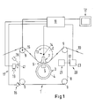
- Fig. 1 schematically a Breitnip-Bandkalander 1 is shown.
- the wide-nip belt calender has two opposing rollers 2, 3.
- the top of the in Fig. 1 shown rollers is a metallic cylinder roller 2.
- the lower of the in Fig. 1 Rolls shown is a hollow cylinder roller 3.
- the hollow cylinder roller 3 has a cylinder jacket 4, which is supported on a support bar 5.
- the cylinder jacket 4 can slide on corresponding sliding elements of the Abstützbalkens 5, which are not shown in detail here for reasons of clarity.
- the nip 6 is a so-called broad nip.
- the force curve 7 of the nip 6 is in Fig. 1 indicated schematically.
- the wide-nip belt calender 1 has a calender belt 8, which is passed through the nip 6.
- guide rollers 9 are provided which guide the calender belt 8 accordingly.
- the calender belt 8 supports the paper web 10 to be calendered during the passage through the wide-nip belt calender 1.
- the calendering belt 8 supports the paper web 10 to be calendered in the area of the nip 6 toward the cylinder jacket 4.
- the calender belt 8 may in particular be a thin-walled metal band, but also a composite band.
- the calender belt 8 is loaded in a different manner during the circulation by the wide-nip belt calender 1. For example, bending in the area of the deflection rollers 9 and in the area of the rollers 2, 3 results in repeated bending of the calender belt 8 in different directions. In addition, there is a wear of the calender belt 8 by friction. Another effect can occur when a bearing of the guide rollers 9 and / or the rollers 2, 3 has a damage or is slightly warped. Such a defect can lead to warping of the calender belt 8, which can very quickly lead to tearing of the calender belt 8.
- a continuous check of the properties (quality) of the calender belt 8 is made during operation of the wide-nip belt calender 1 carried out.
- Fig. 1 There are five different measuring devices provided. Of course, the number of measuring devices can be increased or decreased depending on the application. Also, certain measuring devices may be provided twice or more frequently.
- An electronic controller 11 receives the measurement signals of the individual sensor devices and averages them both in terms of time as well as with respect to the source. It can also be a weighted average. For example, the measuring signal of a measuring device 20 that uses radioactive rays can be weighted higher than the vibration signals of a bearing bushing 9.
- a residual life of the calendered belt 8 is specified as ten hours, but production must be interrupted in any case in five hours, since, for example, a product change is being carried out, it is worth considering to replace the calender belt 8 already "prematurely" in order to avoid a repeated interruption of the production process.
- the wide-nip band calendering device is stopped fully automatically, so that an accident caused by carelessness or misoperation is avoided.
- a presently not shown accelerometer 14 is shown at the bearing point 13 of the cylinder roller 2.
- the acceleration measuring sensor 14 measures vibrations of the cylinder roller 2 in the region of the bearing axis 13.
- Such vibrations can be caused, for example, by different thicknesses or (macroscopic) cracks in the calender belt 8.
- vibrations can also be caused by a defective bearing.
- the characteristic of the resulting vibrations is usually somewhat different, so that a distinction can be made with regard to the type of error due to the vibration spectrum recorded by the acceleration measuring sensor 14.
- the acceleration sensor 14 can detect not only irregularities of the calender belt 8 but also defective bearings and similar defects is not disadvantageous but on the contrary advantageous. For such errors can also have a negative impact on the safety of the wide-nip strip calender 1 or on the quality of the paper web 10 processed by it.
- a tension measuring box 15 is provided.
- the tensile load cell 15 is used to measure the force which is exerted on the corresponding deflection roller 9 by the cylindrical rollers 2, 3, mediated by the calender belt 8.
- the cylindrical roller 2 is actively driven, whereas the hollow cylinder roller 3 and the guide rollers 9 passively pass.
- a different signal is recorded by the Wermessdose 15.
- Another measuring sensor is in the form of a microphone 16 in the region of one of the deflection rollers 9.
- the deflection (from straight to curved and curved back to straight) produces a characteristic acoustic signal picked up by the microphone 16.
- the corresponding acoustic spectrum generated by the calender belt 8 is an indication of the properties of the calender belt 8, in particular with respect to whether ma-microscopic cracks or defects are present in the calender belt 8.
- the laser measuring system 17 has a laser 18 and an associated camera, which in the present case is in the form of a CCD camera 19.
- the laser 18 emits a laser beam 41 in the direction of the calender belt 8.
- the laser beam 41 can be expanded, for example, with the aid of beam splitters, beam expanders and similar optical devices.
- the light 41 reflected by the calender belt 8 has a corresponding interference pattern (e.g., speckle interferometry) from which information about surface imperfections, macroscopic cracks and soiling of the calender belt 8, as well as other information, can be obtained.
- the reflected, interfered laser light 41 is picked up by the CCD camera 19, and the digital signals thus obtained are relayed to the controller 11. In the controller 11, these can be evaluated with a suitable image recognition software or in a similar manner.
- the radioactive transilluminator 20 has a source 21 of radioactive radiation 20.
- a radioactive isotope can be used.
- an X-ray tube 21 is used.
- the X-ray radiation 22 emanating from the X-ray tube 21 passes through the calendering belt 8 and is picked up by the X-ray detector 23.
- the signals obtained by the X-ray detector 23 are also forwarded to the controller 11 and evaluated by this suitable.
- a single, fixed sensor is not sufficient to check the entire width of the calender belt 8.
- Another possibility is to arrange the corresponding sensor elements movable on a rail, so that they can also check the entire width of the calender belt 8 by a movement. This is related to the in Fig. 3 shown example explained in more detail.
- Fig. 2 an optical arrangement of several CCD line scan cameras 25 is shown.
- the CCD line scan cameras 25 are arranged on a carrier 26.
- the CCD line cameras 25 each have a sensor area 27 in which the optical signal (the image) is received.
- the CCD line scan cameras 25 have an integrated illumination unit 28, so that even in unfavorable lighting conditions or in a correspondingly problematic installation position of the CCD line scan cameras 25 sufficient for the sensors 27 of the CCD line scan-25 illumination can be ensured ,
- the individual CCD line scan cameras 25 are arranged offset from one another, so that in each case in the end regions 29 of the CCD line scan cameras 25 overlap areas 29 result. By means of these overlapping regions 29, a complete inspection of the calender belt 8 can be ensured. Of course, the size of the overlapping regions 29 is not too large to choose from economic considerations out. Incidentally, the CCD line scan cameras 25 can also be arranged at an angle to the direction of movement of the calender belt 8.
- interferometric measuring methods can be sensitive to vibrations or (for example thermally induced) deflections of the carrier 26.
- vibrations or (for example thermally induced) deflections of the carrier 26 In the case of oscillations, it may still be possible to improve the properties of the generated measurement signal by averaging the measured value over time. In deflections of the carrier 26, this is not possible.
- mass-caused deflections of the carrier 26 can occur.
- thermal deflections can also result since calender rolls, as already mentioned, are often also heated. A compensation of the occurring measurement errors is only possible if the extent of the deflection is known.
- a strain gauge 30 is provided.
- the measured values obtained from this are likewise fed to the controller 11, which takes them into account accordingly in the evaluation of the signal of the CCD line scan cameras 25.
- other measuring methods are also possible here, such as an optical interferometric measurement, a temperature scanner with a vibrating mirror, a line scanner, etc.
- the use of a larger number of sensors, as in the optical arrangement 24 according to FIG Fig. 2 the case is particularly appropriate when the individual sensors are relatively inexpensive. In this way can be dispensed with moving mechanical parts, which can result in a corresponding cost reduction. In particular, the maintenance costs of such an arrangement can be reduced. Furthermore, the properties of the calender belt 8 can be measured continuously over the entire width. Thus, after one revolution of the calender belt 8, complete information is available over the entire surface of the calender belt 8. As a result, for example, damage events can be registered much faster.
- FIG Fig. 3 Another way to obtain information across the entire width of the calender belt 8 is in FIG Fig. 3 shown.
- the sensor assembly 20 for example, the radioactive transillumination unit off Fig. 1 ) slidably disposed on a support rail 31, 32.
- the radioactive transillumination unit 20 has two units formed separately from each other, namely an X-ray tube 21 and an X-ray detector 23, which are respectively arranged on opposite sides of the calendering belt 8, two retaining rails 31, 32 are provided accordingly.
- the movement of the x-ray tube 21 and of the x-ray detector 23 (indicated by the double arrows) along the corresponding holding rail 31, 32 is coordinated with one another such that x-ray tube 21 and x-ray detector 23 move in synchronism with one another.
- the outgoing from the X-ray tube 21 X-ray radiation 22 are detected by the X-ray detector 23 at any time.
- the structure with a movable arrangement is particularly suitable for detector arrangements in which the source and / or the sensor are expensive to purchase and / or in operation. This is usually the case with radioactive acceleration units 20.
- this time period is sufficiently small during normal operating times of calender bands 8, so that this is not a problem. If, in addition to the radioactive radioscopy unit 20, further detectors (such as the optical arrangement 24 according to FIGS Fig. 2 ) can be responded to quickly occurring, unforeseen events nevertheless very quickly.
- Another way to reduce the amount of time required to measure the entire calender belt 8 is to have two radioactive transilluminators 20.
- the two detector units then each measure a partial area (in the case of two detector units, half) of the calender belt 8.
- the time required to measure the entire surface of the calender belt 8, decreases accordingly (with two detector units it halves).
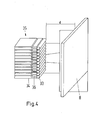
- Fig. 4 is a particularly suitable for the realization of the invention sensor arrangement shown schematically.
- a cell camera 35 can be seen, which is arranged at a working distance d from the calender belt 8, and checks the surface of the calender belt 8.
- the cell camera 35 is composed of a plurality of individual light-emitting diodes 34.
- the light emitted by the light-emitting diodes 34 is reflected by the surface of the calender belt 8.
- the reflected light enters one of the microlenses 33, which have a greater longitudinal extent ("perpendicular" to the plane of the drawing).
- the microlenses 33 are thus formed as a type of "cylindrical lens".
- the light focused by the microlenses 33 falls on a photodiode line 36 assigned to the respective microlenses 33.
- Such a cell camera 35 is particularly suitable for interferometric methods. It is therefore particularly suitable for use in connection with a check of the calendering belt 8 of a wide-nip belt calender 1 (see Fig. 1 ) according to the present invention.
- FIG. 5 Finally, another advantageous sensor system is shown, which is particularly suitable for the realization of the invention. This is a laser triangulation system 37.
- a laser beam 41 is emitted by a laser 38 to a certain surface point 40 on the surface of the calender belt 8.
- the surface point 40 reflects in dependence the surface texture and the surface structure and the position of the calender belt 8, the laser beam 41 incident in the surface point 40.
- the emitted light intensity is different depending on the emission direction.
- the light 41 emitted by the surface point 40 is received by a corresponding number of light receivers 39 as a function of the solid angle.
- a number of three, four, five or six light receivers 39 proves to be sufficient to achieve a sufficient measurement accuracy.
- the signals received by the light receivers 39 are appropriately correlated and evaluated. In this way, information about the properties of the calender belt 8 can be obtained.
Landscapes
- Paper (AREA)
- Investigating Strength Of Materials By Application Of Mechanical Stress (AREA)
- Tyre Moulding (AREA)
- Sewing Machines And Sewing (AREA)
- Casting Or Compression Moulding Of Plastics Or The Like (AREA)
Applications Claiming Priority (1)
| Application Number | Priority Date | Filing Date | Title |
|---|---|---|---|
| DE102007045895A DE102007045895A1 (de) | 2007-09-26 | 2007-09-26 | Bandkalandervorrichtung und Verfahren zum Betrieb einer Bandkalandervorrichtung |
Publications (3)
| Publication Number | Publication Date |
|---|---|
| EP2042654A2 true EP2042654A2 (fr) | 2009-04-01 |
| EP2042654A3 EP2042654A3 (fr) | 2010-02-24 |
| EP2042654B1 EP2042654B1 (fr) | 2011-07-06 |
Family
ID=40227520
Family Applications (1)
| Application Number | Title | Priority Date | Filing Date |
|---|---|---|---|
| EP08164625A Not-in-force EP2042654B1 (fr) | 2007-09-26 | 2008-09-18 | Calandre à bande et procédé de fonctionnement d'une calandre à bande |
Country Status (3)
| Country | Link |
|---|---|
| EP (1) | EP2042654B1 (fr) |
| AT (1) | ATE515596T1 (fr) |
| DE (1) | DE102007045895A1 (fr) |
Cited By (8)
| Publication number | Priority date | Publication date | Assignee | Title |
|---|---|---|---|---|
| WO2009156314A1 (fr) * | 2008-06-26 | 2009-12-30 | Voith Patent Gmbh | Procédé et dispositif de détection de l’état d’une bande |
| WO2012175670A1 (fr) * | 2011-06-22 | 2012-12-27 | Voith Patent Gmbh | Surveillance d'un habillage |
| WO2013139890A1 (fr) * | 2012-03-21 | 2013-09-26 | Voith Patent Gmbh | Toile de fabrication de papier |
| AT513550A3 (de) * | 2012-10-25 | 2014-07-15 | Metso Paper Inc | Vorrichtung zum Behandeln einer Faserbahn |
| DE102013105599A1 (de) * | 2013-05-31 | 2014-12-04 | Thyssenkrupp Steel Europe Ag | Verfahren und Vorrichtung zur Messung von Bandschwingungen einer Bandbehandlungsanlage und von einer Bandbehandlungsanlage |
| CN109416315A (zh) * | 2016-05-06 | 2019-03-01 | 博西迈科思公司 | 机器视觉方法和系统 |
| CN109416327A (zh) * | 2016-05-06 | 2019-03-01 | 博西迈科思公司 | 用于监控制造过程的机器视觉方法和系统 |
| EP3858590B1 (fr) | 2020-01-29 | 2023-08-02 | Siempelkamp Maschinen- und Anlagenbau GmbH | Procédé de surveillance d'une bande d'acier dans une presse continue et presse continue |
Citations (8)
| Publication number | Priority date | Publication date | Assignee | Title |
|---|---|---|---|---|
| EP0978589A2 (fr) | 1998-08-06 | 2000-02-09 | Voith Sulzer Papiertechnik Patent GmbH | Dispositif de réduction active de vibrations non-voulues d'un rouleau rotatif; Dispositif pour traiter une bande de matériau, en particulier de papier ou carton; Rouleau |
| US20020152630A1 (en) | 2001-04-20 | 2002-10-24 | Lindsay Jeffrey Dean | Systems for tissue dried with metal bands |
| WO2003064761A1 (fr) | 2002-01-29 | 2003-08-07 | Metso Paper, Inc. | Dispositif de traitement et procede d'utilisation de ce dispositif pour traiter une nappe fibreuse enduite ou non enduite |
| EP1484442A1 (fr) | 2003-06-07 | 2004-12-08 | Voith Paper Patent GmbH | Procédé de traitement d'une bande, en particulier d'une bande de papier |
| WO2005056921A1 (fr) | 2003-12-10 | 2005-06-23 | Metso Paper, Inc. | Procede de controle de parametres de fonctionnement dans un appareil pour le traitement d'une nappe fibreuse et dispositif de mise en oeuvre dudit procede |
| EP1693509A1 (fr) | 2005-02-21 | 2006-08-23 | Voith Paper Patent GmbH | Surveillance d'un rouleau de presse |
| DE102005007833A1 (de) | 2005-02-21 | 2006-08-31 | Voith Paper Patent Gmbh | Glättanordnung |
| DE202007007404U1 (de) | 2006-06-06 | 2007-07-26 | Metso Paper, Inc. | Mit Metallbandumlauf ausgerüstete Faserbahnbehandlungsvorrichtung einer Papier-/Kartonmaschine und/oder Nachbehandlungsmaschine |
-
2007
- 2007-09-26 DE DE102007045895A patent/DE102007045895A1/de not_active Withdrawn
-
2008
- 2008-09-18 EP EP08164625A patent/EP2042654B1/fr not_active Not-in-force
- 2008-09-18 AT AT08164625T patent/ATE515596T1/de active
Patent Citations (8)
| Publication number | Priority date | Publication date | Assignee | Title |
|---|---|---|---|---|
| EP0978589A2 (fr) | 1998-08-06 | 2000-02-09 | Voith Sulzer Papiertechnik Patent GmbH | Dispositif de réduction active de vibrations non-voulues d'un rouleau rotatif; Dispositif pour traiter une bande de matériau, en particulier de papier ou carton; Rouleau |
| US20020152630A1 (en) | 2001-04-20 | 2002-10-24 | Lindsay Jeffrey Dean | Systems for tissue dried with metal bands |
| WO2003064761A1 (fr) | 2002-01-29 | 2003-08-07 | Metso Paper, Inc. | Dispositif de traitement et procede d'utilisation de ce dispositif pour traiter une nappe fibreuse enduite ou non enduite |
| EP1484442A1 (fr) | 2003-06-07 | 2004-12-08 | Voith Paper Patent GmbH | Procédé de traitement d'une bande, en particulier d'une bande de papier |
| WO2005056921A1 (fr) | 2003-12-10 | 2005-06-23 | Metso Paper, Inc. | Procede de controle de parametres de fonctionnement dans un appareil pour le traitement d'une nappe fibreuse et dispositif de mise en oeuvre dudit procede |
| EP1693509A1 (fr) | 2005-02-21 | 2006-08-23 | Voith Paper Patent GmbH | Surveillance d'un rouleau de presse |
| DE102005007833A1 (de) | 2005-02-21 | 2006-08-31 | Voith Paper Patent Gmbh | Glättanordnung |
| DE202007007404U1 (de) | 2006-06-06 | 2007-07-26 | Metso Paper, Inc. | Mit Metallbandumlauf ausgerüstete Faserbahnbehandlungsvorrichtung einer Papier-/Kartonmaschine und/oder Nachbehandlungsmaschine |
Cited By (16)
| Publication number | Priority date | Publication date | Assignee | Title |
|---|---|---|---|---|
| WO2009156314A1 (fr) * | 2008-06-26 | 2009-12-30 | Voith Patent Gmbh | Procédé et dispositif de détection de l’état d’une bande |
| WO2012175670A1 (fr) * | 2011-06-22 | 2012-12-27 | Voith Patent Gmbh | Surveillance d'un habillage |
| CN103620114A (zh) * | 2011-06-22 | 2014-03-05 | 福伊特专利公司 | 覆盖物的监测 |
| WO2013139890A1 (fr) * | 2012-03-21 | 2013-09-26 | Voith Patent Gmbh | Toile de fabrication de papier |
| AT513550A3 (de) * | 2012-10-25 | 2014-07-15 | Metso Paper Inc | Vorrichtung zum Behandeln einer Faserbahn |
| AT513550B1 (de) * | 2012-10-25 | 2015-02-15 | Metso Paper Inc | Vorrichtung zum Behandeln einer Faserbahn |
| DE102013105599A1 (de) * | 2013-05-31 | 2014-12-04 | Thyssenkrupp Steel Europe Ag | Verfahren und Vorrichtung zur Messung von Bandschwingungen einer Bandbehandlungsanlage und von einer Bandbehandlungsanlage |
| CN109416327A (zh) * | 2016-05-06 | 2019-03-01 | 博西迈科思公司 | 用于监控制造过程的机器视觉方法和系统 |
| CN109416315A (zh) * | 2016-05-06 | 2019-03-01 | 博西迈科思公司 | 机器视觉方法和系统 |
| JP2019517193A (ja) * | 2016-05-06 | 2019-06-20 | プロセメク オーワイ | マシンビジョンの方法及びシステム |
| EP3452811A4 (fr) * | 2016-05-06 | 2020-01-22 | Procemex Oy | Procédé et système de vision artificielle pour surveiller des processus de fabrication |
| US10884401B2 (en) | 2016-05-06 | 2021-01-05 | Procemex Oy | Machine vision method and system for monitoring manufacturing processes |
| CN109416315B (zh) * | 2016-05-06 | 2021-10-15 | 博西迈科思公司 | 机器视觉方法和系统 |
| CN109416327B (zh) * | 2016-05-06 | 2021-10-26 | 博西迈科思公司 | 用于监控制造过程的机器视觉方法和系统 |
| EP4019948A1 (fr) * | 2016-05-06 | 2022-06-29 | Procemex Oy | Procédé et système de vision artificielle pour surveiller des processus de fabrication |
| EP3858590B1 (fr) | 2020-01-29 | 2023-08-02 | Siempelkamp Maschinen- und Anlagenbau GmbH | Procédé de surveillance d'une bande d'acier dans une presse continue et presse continue |
Also Published As
| Publication number | Publication date |
|---|---|
| EP2042654B1 (fr) | 2011-07-06 |
| ATE515596T1 (de) | 2011-07-15 |
| DE102007045895A1 (de) | 2009-04-09 |
| EP2042654A3 (fr) | 2010-02-24 |
Similar Documents
| Publication | Publication Date | Title |
|---|---|---|
| EP2042654B1 (fr) | Calandre à bande et procédé de fonctionnement d'une calandre à bande | |
| JP6653307B2 (ja) | 製品の製造方法及び製品の製造装置 | |
| DE69919538T2 (de) | Verfahren ung vorrichtung zur konditionierung einer walze, insbesondere von einer walze in einer papierherstellungs- oder veredelungsvorrichtung | |
| DE102017206179A1 (de) | Schleifvorrichtung | |
| EP2304105B1 (fr) | Procédé et dispositif de détection de l'état d'une bande | |
| DE19882374B4 (de) | Verfahren zur Bestimmung der Qualität der Formierung einer Bobine oder Rolle einer Papier - oder Kartonbahn und zur Steuerung der Bobinen - oder Rollenformierung und - wicklung | |
| CH699160B1 (de) | Vorrichtung zum Erfassen eines Parameters an mehreren, einem Streckwerk einer Spinnereimaschine zugeführten Faserbändern. | |
| EP3487642A1 (fr) | Procédé et dispositif permettant de déterminer la planéité d'un matériau en bande et installation de traitement dotée d'un tel dispositif | |
| DE69832961T2 (de) | Verfahren zum nachweis von verunreinigung und/oder beschädigung auf einer durch einen walzenspalt laufenden fläche in einer papier- oder papierveredelungsmaschine | |
| EP3290154B1 (fr) | Procédé de surveillance d'un processus de meulage | |
| WO2008012093A2 (fr) | Procédé et agencement pour déterminer la qualité du fil et/ou la qualité de bobine d'un fil continu à l'aide d'anémometrie laser doppler | |
| DE10296651B4 (de) | Verfahren zum Überwachen des Betriebs einer Schaberbaugruppe in einer Papiermaschine und Schaberbaugruppe zum Ausführen dieses Verfahrens | |
| DE102008013488A1 (de) | Vorrichtung zur Dickenmessung und Verfahren hierfür | |
| EP3290582A1 (fr) | Procédé de fonctionnement d'une machine destinée à fabriquer et/ou traiter une bande de matériau | |
| WO2009077218A1 (fr) | Procédé et dispositif pour détecter au moins une grandeur caractérisant au moins indirectement les propriétés d'une surface dans un équipement de traitement d'une bande de matériau, et procédé pour optimiser le mode de fonctionnement d'un équipement de traitement d'une bande de matériau | |
| EP2145693A1 (fr) | Surveillance d'un flux de milieu d'application lors de l'application sur une bande de papier, de carton ou autre matière fibreuse | |
| EP4003889B1 (fr) | Procédé d'enroulement d'une bande de non-tissés de laine minérale et appareil pour effectuer le procédé | |
| WO2011076454A1 (fr) | Procédé et dispositif pour détecter des défauts de surface sur des cylindres | |
| EP0308731B1 (fr) | Procédé et dispositif de réglage d'une laineuse | |
| DE102014019336B3 (de) | Vorrichtung zum Schutz der Fenster von Laserabstandssensoren | |
| DE10239154B4 (de) | Kalander und Verfahren zum Kalandrieren einer Materialbahn | |
| EP2384379A1 (fr) | Procédé et dispositif d'identification d'une déchirure d'une bande de matériau | |
| DE202011108575U1 (de) | Prüfeinrichtung und Vorrichtung zur Herstellung und/oder Veredelung einer Materialbahn | |
| EP1681255B1 (fr) | Changeur de rouleaux pour alimenter une bande de matériau | |
| DE102007056499B4 (de) | Verfahren und Vorrichtung zur Abrisserkennung an papierherstellenden und weiterverarbeitenden Maschinen |
Legal Events
| Date | Code | Title | Description |
|---|---|---|---|
| PUAI | Public reference made under article 153(3) epc to a published international application that has entered the european phase |
Free format text: ORIGINAL CODE: 0009012 |
|
| AK | Designated contracting states |
Kind code of ref document: A2 Designated state(s): AT BE BG CH CY CZ DE DK EE ES FI FR GB GR HR HU IE IS IT LI LT LU LV MC MT NL NO PL PT RO SE SI SK TR |
|
| AX | Request for extension of the european patent |
Extension state: AL BA MK RS |
|
| RIN1 | Information on inventor provided before grant (corrected) |
Inventor name: ROENCHEN, MICHAEL Inventor name: STEININGER, HANS-PETER Inventor name: ZIMMERMANN, LOTHAR, DR. Inventor name: SCHNYDER, EUGEN Inventor name: ROTHFUSS, ULRICH Inventor name: RHEIMS, DR., JOERG Inventor name: NIEMANN, JOCHEN, DR. Inventor name: MOSER, JOHANN Inventor name: KARNER, NORBERT Inventor name: FEICHTINGER, MANFRED Inventor name: CRAMER, DIRK |
|
| PUAL | Search report despatched |
Free format text: ORIGINAL CODE: 0009013 |
|
| AK | Designated contracting states |
Kind code of ref document: A3 Designated state(s): AT BE BG CH CY CZ DE DK EE ES FI FR GB GR HR HU IE IS IT LI LT LU LV MC MT NL NO PL PT RO SE SI SK TR |
|
| AX | Request for extension of the european patent |
Extension state: AL BA MK RS |
|
| RIC1 | Information provided on ipc code assigned before grant |
Ipc: D21G 9/00 20060101ALI20100118BHEP Ipc: D21F 7/00 20060101ALI20100118BHEP Ipc: D21G 1/00 20060101AFI20090122BHEP |
|
| 17P | Request for examination filed |
Effective date: 20100824 |
|
| 17Q | First examination report despatched |
Effective date: 20100914 |
|
| AKX | Designation fees paid |
Designated state(s): AT DE FI IT SE |
|
| GRAP | Despatch of communication of intention to grant a patent |
Free format text: ORIGINAL CODE: EPIDOSNIGR1 |
|
| RIC1 | Information provided on ipc code assigned before grant |
Ipc: D21G 9/00 20060101ALI20110121BHEP Ipc: D21F 7/00 20060101ALI20110121BHEP Ipc: D21G 1/00 20060101AFI20110121BHEP |
|
| RTI1 | Title (correction) |
Free format text: BAND CALENDER AND METHOD FOR OPERATING A BAND CALENDER |
|
| GRAS | Grant fee paid |
Free format text: ORIGINAL CODE: EPIDOSNIGR3 |
|
| GRAA | (expected) grant |
Free format text: ORIGINAL CODE: 0009210 |
|
| AK | Designated contracting states |
Kind code of ref document: B1 Designated state(s): AT DE FI IT SE |
|
| REG | Reference to a national code |
Ref country code: DE Ref legal event code: R096 Ref document number: 502008004106 Country of ref document: DE Effective date: 20110825 |
|
| REG | Reference to a national code |
Ref country code: SE Ref legal event code: TRGR |
|
| PGFP | Annual fee paid to national office [announced via postgrant information from national office to epo] |
Ref country code: FI Payment date: 20110914 Year of fee payment: 4 Ref country code: DE Payment date: 20110923 Year of fee payment: 4 Ref country code: SE Payment date: 20110923 Year of fee payment: 4 |
|
| PLBE | No opposition filed within time limit |
Free format text: ORIGINAL CODE: 0009261 |
|
| STAA | Information on the status of an ep patent application or granted ep patent |
Free format text: STATUS: NO OPPOSITION FILED WITHIN TIME LIMIT |
|
| 26N | No opposition filed |
Effective date: 20120411 |
|
| REG | Reference to a national code |
Ref country code: DE Ref legal event code: R097 Ref document number: 502008004106 Country of ref document: DE Effective date: 20120411 |
|
| PG25 | Lapsed in a contracting state [announced via postgrant information from national office to epo] |
Ref country code: FI Free format text: LAPSE BECAUSE OF NON-PAYMENT OF DUE FEES Effective date: 20120918 Ref country code: SE Free format text: LAPSE BECAUSE OF NON-PAYMENT OF DUE FEES Effective date: 20120919 |
|
| REG | Reference to a national code |
Ref country code: SE Ref legal event code: EUG |
|
| PG25 | Lapsed in a contracting state [announced via postgrant information from national office to epo] |
Ref country code: DE Free format text: LAPSE BECAUSE OF NON-PAYMENT OF DUE FEES Effective date: 20130403 |
|
| PG25 | Lapsed in a contracting state [announced via postgrant information from national office to epo] |
Ref country code: IT Free format text: LAPSE BECAUSE OF NON-PAYMENT OF DUE FEES Effective date: 20120918 |
|
| REG | Reference to a national code |
Ref country code: DE Ref legal event code: R119 Ref document number: 502008004106 Country of ref document: DE Effective date: 20130403 |
|
| REG | Reference to a national code |
Ref country code: AT Ref legal event code: MM01 Ref document number: 515596 Country of ref document: AT Kind code of ref document: T Effective date: 20130918 |
|
| PG25 | Lapsed in a contracting state [announced via postgrant information from national office to epo] |
Ref country code: AT Free format text: LAPSE BECAUSE OF NON-PAYMENT OF DUE FEES Effective date: 20130918 |