EP2145693A1 - Surveillance d'un flux de milieu d'application lors de l'application sur une bande de papier, de carton ou autre matière fibreuse - Google Patents
Surveillance d'un flux de milieu d'application lors de l'application sur une bande de papier, de carton ou autre matière fibreuse Download PDFInfo
- Publication number
- EP2145693A1 EP2145693A1 EP08160502A EP08160502A EP2145693A1 EP 2145693 A1 EP2145693 A1 EP 2145693A1 EP 08160502 A EP08160502 A EP 08160502A EP 08160502 A EP08160502 A EP 08160502A EP 2145693 A1 EP2145693 A1 EP 2145693A1
- Authority
- EP
- European Patent Office
- Prior art keywords
- application
- monitoring
- fibrous web
- parameter deviation
- medium flow
- Prior art date
- Legal status (The legal status is an assumption and is not a legal conclusion. Google has not performed a legal analysis and makes no representation as to the accuracy of the status listed.)
- Withdrawn
Links
- 239000011248 coating agent Substances 0.000 title claims abstract description 39
- 238000012544 monitoring process Methods 0.000 title claims abstract description 39
- 239000000123 paper Substances 0.000 title abstract description 7
- 239000000835 fiber Substances 0.000 title description 2
- 238000000576 coating method Methods 0.000 claims abstract description 38
- 238000000034 method Methods 0.000 claims abstract description 38
- 238000001514 detection method Methods 0.000 claims abstract description 36
- 230000009471 action Effects 0.000 claims abstract description 15
- 238000004140 cleaning Methods 0.000 claims description 15
- 230000003287 optical effect Effects 0.000 claims description 11
- 238000012545 processing Methods 0.000 claims description 10
- 230000008569 process Effects 0.000 claims description 5
- 230000005855 radiation Effects 0.000 claims description 4
- 230000001960 triggered effect Effects 0.000 claims 1
- 239000002657 fibrous material Substances 0.000 abstract 3
- 230000005856 abnormality Effects 0.000 abstract 1
- 230000007547 defect Effects 0.000 description 27
- 239000012535 impurity Substances 0.000 description 12
- 238000011109 contamination Methods 0.000 description 6
- 230000035508 accumulation Effects 0.000 description 5
- 238000009825 accumulation Methods 0.000 description 5
- 239000003990 capacitor Substances 0.000 description 4
- 230000008859 change Effects 0.000 description 4
- 238000002310 reflectometry Methods 0.000 description 4
- 230000008719 thickening Effects 0.000 description 3
- 238000007766 curtain coating Methods 0.000 description 2
- 230000002950 deficient Effects 0.000 description 2
- 238000001914 filtration Methods 0.000 description 2
- 230000005484 gravity Effects 0.000 description 2
- 238000004519 manufacturing process Methods 0.000 description 2
- 230000035699 permeability Effects 0.000 description 2
- 238000010926 purge Methods 0.000 description 2
- 230000005236 sound signal Effects 0.000 description 2
- XLYOFNOQVPJJNP-UHFFFAOYSA-N water Substances O XLYOFNOQVPJJNP-UHFFFAOYSA-N 0.000 description 2
- 238000010521 absorption reaction Methods 0.000 description 1
- 230000004913 activation Effects 0.000 description 1
- 239000000654 additive Substances 0.000 description 1
- 230000008901 benefit Effects 0.000 description 1
- 230000005540 biological transmission Effects 0.000 description 1
- 230000015572 biosynthetic process Effects 0.000 description 1
- 238000013461 design Methods 0.000 description 1
- 238000011161 development Methods 0.000 description 1
- 238000009826 distribution Methods 0.000 description 1
- 230000000694 effects Effects 0.000 description 1
- 238000011156 evaluation Methods 0.000 description 1
- 238000007730 finishing process Methods 0.000 description 1
- 239000012530 fluid Substances 0.000 description 1
- 238000011010 flushing procedure Methods 0.000 description 1
- 238000009499 grossing Methods 0.000 description 1
- 230000003116 impacting effect Effects 0.000 description 1
- 238000012423 maintenance Methods 0.000 description 1
- 238000002156 mixing Methods 0.000 description 1
- 230000000149 penetrating effect Effects 0.000 description 1
- 239000000049 pigment Substances 0.000 description 1
- 238000001228 spectrum Methods 0.000 description 1
- 239000000126 substance Substances 0.000 description 1
- 238000002834 transmittance Methods 0.000 description 1
- 238000011144 upstream manufacturing Methods 0.000 description 1
- 238000013022 venting Methods 0.000 description 1
- 230000000007 visual effect Effects 0.000 description 1
- 239000011800 void material Substances 0.000 description 1
- 239000002699 waste material Substances 0.000 description 1
Images


Classifications
-
- D—TEXTILES; PAPER
- D21—PAPER-MAKING; PRODUCTION OF CELLULOSE
- D21H—PULP COMPOSITIONS; PREPARATION THEREOF NOT COVERED BY SUBCLASSES D21C OR D21D; IMPREGNATING OR COATING OF PAPER; TREATMENT OF FINISHED PAPER NOT COVERED BY CLASS B31 OR SUBCLASS D21G; PAPER NOT OTHERWISE PROVIDED FOR
- D21H23/00—Processes or apparatus for adding material to the pulp or to the paper
- D21H23/02—Processes or apparatus for adding material to the pulp or to the paper characterised by the manner in which substances are added
- D21H23/22—Addition to the formed paper
- D21H23/46—Pouring or allowing the fluid to flow in a continuous stream on to the surface, the entire stream being carried away by the paper
- D21H23/48—Curtain coaters
-
- B—PERFORMING OPERATIONS; TRANSPORTING
- B05—SPRAYING OR ATOMISING IN GENERAL; APPLYING FLUENT MATERIALS TO SURFACES, IN GENERAL
- B05C—APPARATUS FOR APPLYING FLUENT MATERIALS TO SURFACES, IN GENERAL
- B05C11/00—Component parts, details or accessories not specifically provided for in groups B05C1/00 - B05C9/00
- B05C11/10—Storage, supply or control of liquid or other fluent material; Recovery of excess liquid or other fluent material
- B05C11/1002—Means for controlling supply, i.e. flow or pressure, of liquid or other fluent material to the applying apparatus, e.g. valves
- B05C11/1007—Means for controlling supply, i.e. flow or pressure, of liquid or other fluent material to the applying apparatus, e.g. valves responsive to condition of liquid or other fluent material
-
- B—PERFORMING OPERATIONS; TRANSPORTING
- B05—SPRAYING OR ATOMISING IN GENERAL; APPLYING FLUENT MATERIALS TO SURFACES, IN GENERAL
- B05C—APPARATUS FOR APPLYING FLUENT MATERIALS TO SURFACES, IN GENERAL
- B05C5/00—Apparatus in which liquid or other fluent material is projected, poured or allowed to flow on to the surface of the work
- B05C5/005—Curtain coaters
Definitions
- the invention relates to a method for monitoring a coating medium flow of an application device when applied to a paper, cardboard or other fibrous web, in detail with the features of the preamble of claim 1.
- the invention further relates to a device for monitoring according to the preamble of claim 17.
- the application medium in particular pigment-containing coating color, results from a color supply system upstream of the application unit.
- the coating color is usually supplied to the commissioned work after mixing, filtering and venting.
- the order is often done either in the form of a free falling onto the web job media curtain with a curtain applicator or Curtain Coater or in the form of a pressurized media jet with a free-jet nozzle device.
- the latter device represents a predosing system, which is followed by a metering or equalizing device with a so-called doctoring element.
- the application medium is applied substantially following the principle of gravity.
- the web to be coated moves below at least one (in the case of multiple application) curtain nozzle of the application device, wherein the application device is located at a predefined distance from the moving surface of the fibrous web. This Distance has overcome over the machine width formed curtain or the beam of the free-jet nozzle device.
- the amount of coating applied is deposited as a contour line on the surface of the web.
- This job type requires the job media curtain to be even and closed across the machine width. In some cases, however, an undesirable tearing of the application media curtain is observed. The tearing is essentially due to impurities in the feed path in the application media supply system, in particular in the region of the nozzle. Once contaminated, the impurities can not pass through the nozzle outlet itself. In this case, the residual curtain produced at this point no longer closes automatically, as a result of which the fibrous web passing underneath is not coated in the area of the crack.
- the impurities can be removed by a brief manual intervention in the nozzle, which can also be done during operation, but much more critical than the resulting defects on the web are the accumulations of the coating medium right next to the defects. These clumps dry considerably worse than the rest of the contour stroke, which negatively affects the subsequent processing steps. Thus, remnants of these clusters can attach and build up on the machine elements, such as the web-carrying rollers, resulting in further "line defects" on the web. This requires a shutdown of the machine and time-consuming cleaning of the individual areas, which in turn is expensive and means significant production loss. Particularly problematic is the situation when the applicator is followed by a calender, that is, the coated fibrous web after passing through the commissioned work still passes through a calender.
- JP 2002-273309 proposed the use of a detection system for such defects on the free-falling curtain of application medium during the coating process.
- the application medium is optically detected and the images generated are evaluated for the presence of local irregularities out.
- this coated part of the fibrous web is marked in the free curtain as a function of the detection of the occurrence of said irregularities in the application medium and removed in a subsequent process step.
- the method described in this document requires the arrangement of the detection devices in the immediate vicinity of the order media process, which are exposed to contamination. This can lead to misinterpretations.
- the invention is therefore an object of the invention to provide a method and an apparatus which are able to make possible possible line defects as quickly and safely recognizable and, if desired, appropriate measures to eliminate such defects, in particular to initiate negative impact.
- the application medium When operating an application device for applying a coating medium on a moving fibrous web, in particular a paper, cardboard or other fibrous web, the application medium is monitored after exiting the applicator device across the machine width and according to the invention when a local irregularity, in particular Contamination or defect of application medium, an action device activated.
- the monitoring takes place via a monitoring area. This extends transversely to the fibrous web running direction over a predefined minimum width, preferably the machine width, in particular width of the application device. However, the monitoring is preferably carried out over the entire width of the fibrous web or the entire coating area.
- the application medium flow is monitored directly between the dispenser and the impingement on the fibrous web.
- a particularly advantageous application is a so-called curtain applicator, here the homogeneity, especially with regard to the closedness of the curtain over the entire machine width is monitored. Defects, which lead to errors in the coating, are thus already detectable before the order.
- the monitoring can be acoustic or capacitive.
- acoustic waves in the monitoring area are introduced into the order media stream in the former case and received at another location on a receiving device, defining a basic signal, wherein a presence of a locally occurring parameter deviation is detected upon change of the basic signal.
- the introduction of the acoustic waves preferably takes place transversely to the direction of movement of the fibrous web in the application device at a lateral end region of the application medium flow in the direction of the opposite end region over the width of the application medium flow.
- the required elements of the detection device are arranged outside the working area of the application device and the moving fibrous web on both sides of the applicator laterally next to the moving fibrous web, so that impurities are largely avoided at the detection device.
- capacitors are assigned to the application medium flow over the minimum width of the fibrous web, and a local parameter deviation is derived from a change in the permeability number. Even with this method, impurities can be detected in addition to defects.
- Electromagnetic methods used are based on the reflectivity and absorption or transmittance of the coating media stream.
- appropriate radiation or light sources are used, which are directed to one or both sides of the free-falling curtain (or medium beam in example used Freistrahldüsen Kunststoffswerken).
- light rays optical or visible rays
- non-visible rays such as microwaves, infrared rays, gamma rays, etc.
- intensity measuring devices it is possible on the opposite side to detect the proportion of radiation passed through defects, in particular in the freely falling curtain. It is usually sufficient to detect only the presence of defects, since a cleaning of the application device is usually done over the entire machine width. Another possibility is the detection of deviations in the reflectivity over the entire machine width.
- the order media flow is monitored after impacting the fibrous web to be coated.
- an action unit is also actuated here.
- the error in the coating medium caused by the error in the coating is determined and closed on this error or contamination in the applicator.
- the detection device is here, even when arranged on the machine width, not so heavily contaminated, as in the direct arrangement on both sides or immediately before or after the order media flow according to the first embodiment.
- the arrangement of at least the sensors of the detection devices takes place either over the machine width or preferably to shorten the design and reduce the faulty Evaluations triggering impurities laterally to the fibrous web.
- the arrangement is spaced from the order media flow or the coating, so that contact is detected.
- the cleaning can be manually initiated as mentioned or else operated automatically, the cleaning with purely mechanical means (such as a scraper) is carried out with good accessibility of the applicator.
- a hydraulic method for example, a suitable flushing method is used, wherein the purge with pure water as well a fluid can be made with chemical additives.
- Other possibilities are the knocking off of the fibrous web with a very strong expression of the imperfections in the coating with thickening in the marginal areas of the defects.
- the device used to implement the monitoring tasks is described in claim 17.
- the function of the device has already been explained in the description of the method, which is why no repetition should take place here.
- the device according to the invention extends either parallel to the application device across the width, wherein the arrangement can take place on only one side or on both sides of the free-falling curtain or the medium beam from application medium, or laterally next to the fibrous web.
- the detection process is carried out transversely to the fibrous web running direction. This offers next to a lower susceptibility to contamination and the advantage of better accessibility.
- the device according to the invention is assigned to the application medium flow after striking the fibrous web to be coated.
- the device for detecting a parameter deviation comprises, in the simplest case, a sensor depending on the type of monitoring method. It can also be a transmitting device and a receiving device for electromagnetic monitoring, for example by means of camera, wherein a software with the camera data makes a gray value analysis.
- the result can be saved and / or displayed on a monitor. This monitoring result can then be taken as a trigger for example, a railway tee.
- a sensor bar with light grid, or an acoustic (sound waves) or a capacitive (by means of capacitors) monitoring is also possible.
- the solution according to the invention is particularly suitable for the application of application medium, for example in the form of coating color in an application device in the form of a Can be used curtain applicator.
- application medium for example in the form of coating color in an application device in the form of a Can be used curtain applicator.
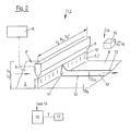
- FIG. 1 schematically illustrates a greatly simplified representation of an applicator 1.
- the curtain applicator 2 is in terms of its basic structure and the basic version, for example, from DE 197 16 647 A1 previously known.
- the application device shown here receives its order media stream 7 from a commissioned with the application unit 2schreibmedienkousaku 9.
- the application medium is then applied from top to bottom and essentially following the principle of gravity on a running relative to a nozzle outlet 10, or moving fibrous web 3.
- the web 3 may be any type of webs, but preferably such coating systems are used to coat paper or board webs.
- the commissioned unit 2 is arranged for this purpose at a predefined distance a to the running surface 4 of the fibrous web 3, so that a curtain 5 from a nozzle 6, which extends continuously and over the entire width b2 of the usually machine-wide commissioned work 2, free and unsupported down can fall down to the surface 4 to be coated or impregnated and there in the amount which is supplied to the surface 4, as a contour line on the surface 4 of the here indicated by arrow direction of the moving fibrous web 3.
- Prerequisite for a on the web width b3 of Fibrous web 3 uniform and homogeneous application free of defects is the uniformity and homogeneity of the curtain 5 over the machine width or at least over the width to be coated or the total width b3 of the fibrous web.
- FIG. 1 illustrates greatly exaggerated the tearing of the curtain 5 and the resulting defect line 12, that is, the part of the fibrous web surface 4, which is not covered by application medium.
- an application media monitoring system 14 which observes the order media stream 7 after exit 10 at the nozzle 6, in particular the homogeneity in thickness and distribution, ie uniformity across the machine width and the occurrence of defects 11, in particular an irregularity initiates measures to eliminate these in the order medium.
- the application media monitoring system 14 is shown schematically here and for this purpose comprises at least one detection device 15. It is therefore possible to detect at least one deviation of a parameter x which characterizes a property of the application medium flow 7 over the width b7 of the application medium flow 7.
- the monitored width of the order media stream 7 is at least the required width b7 'to achieve the required minimum coating width b3' of the fibrous web 3, which preferably corresponds to the total width b3, but may also be smaller, taking into account subsequent Randabtrenn 11,.
- the parameters to be detected thereby characterize at least defects 11, preferably also other irregularities, such as impurities in the application medium flow 7.
- the detection device 15 acts with a device 16 for processing the with the Detection device 15 detected signal together, wherein on the processing means 16 at least one manipulated variable Y for an action unit 17, comprising at least one action means is generated.
- the signal processing device 16 for processing the parameter deviation may be designed as a simple converter which outputs such a signal, which characterizes the occurrence of an irregularity over the machine width in the application medium stream 7, in a corresponding error signal Fs, which is output as an error message is converted.
- the output is preferably acoustic, or optical or capacitive. Combinations are also conceivable.
- the coating process can be interrupted at least for a short time. It is also possible to knock off the fibrous web 3, ie the defective coated part is passed into a waste facility.
- Other possibilities are the formation of at least one manipulated variable Y for controlling the action unit 17, for example, for putting a cleaning device 18 into operation FIG. 1 but only symbolically indicated.
- FIG. 2 illustrated by an embodiment according to FIG. 1 a further second embodiment of the monitoring according to the invention by detecting parameter deviations of the application medium after hitting the fibrous web 3.
- the structure of the application medium monitoring system 14 corresponds to the in FIG. 1 Therefore, the same reference numerals are used for the same elements. Only the detection device 15 is no longer associated with the freely falling curtain 5 but the fibrous web 3 following the coating process.
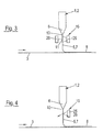
- FIGS. 3 to 5 illustrate greatly simplified possible embodiments of the detection devices 15 and also their arrangement options.
- an arrangement will generally take place after the exit 10 from the nozzle, wherein the arrangement or monitoring of the application medium can take place prior to hitting the fibrous web 3 to be coated or else the recognition Of errors also only after the impact, that is directly on the surface 4 of the fibrous web as in the FIGS. 1 and 2 clarified.
- the application medium in particular the curtain 5 is monitored
- the surface 4 of the fibrous web 3 is monitored, preferably scanned.
- the parameter deviation is detected from a transmission variable
- the parameter deviation is derived from the reflectivity of the application medium flow 7.
- an optical source in particular light source 25
- a receiver 26 On the opposite side of a receiver 26 is arranged, which at least the light passing through the flaws 11, depending on the order media condition that this penetrating light receives and can locate defects based on the differences across the machine width or detect defects.
- optical source 25 and receiver 26 are disposed on the same side of the curtain 5, a parameter deviation is derived from the different reflectivity of the application media stream 7 across the machine width.
- a perspective view according to FIG. 4 is a corresponding light source and receiving unit arranged machine width.
- a device 15 for capacitive monitoring is shown. This is characterized by the arrangement of one, preferably a plurality of capacitors 27 across the machine width, wherein the Error detection as a result of the change in the permeability number occurs when defects in the order media stream 7 occurs.
- FIG. 7 illustrates a schematic simplified representation of a possibility of acoustic monitoring.
- a means 28 for introducing a sound signal for example on the drive side TS in the curtain 5 is provided as a transmitter 29, while a receiver 30 is disposed opposite to the leader side FS or vice versa and receives the signal.
- Parameter deviations produce a deviation from a base signal otherwise set at the receiver 30.
- the detection device 15 in particular the sensor system is installed within the machine width or over the entire machine width b2. According to a further development, it is also conceivable to arrange the sensors outside the application device 1, this applies in particular to the detection devices 15 in order to avoid fouling.
- the detection devices, in particular transmitter and receiver can also be arranged in their assignment to each other transversely to the fibrous web running direction.
- FIG. 8 illustrates a method for optical detection of parameter deviations according to the second embodiment of the inventive solution, as in FIG. 2 clarified.
- a camera 31 is used as detection device 15, which optically scans and detects the entire surveillance area, which extends over the machine width, in particular the width of the coated fibrous web 3.
- the camera 31 is arranged at a distance from the surface 4 of the coated fibrous web 3. Images are continuously created, which are processed and evaluated in the already described signal processing device 16 for processing, so that the necessary measures can be taken according to the result.
Landscapes
- Coating Apparatus (AREA)
- Paper (AREA)
Priority Applications (1)
| Application Number | Priority Date | Filing Date | Title |
|---|---|---|---|
| EP08160502A EP2145693A1 (fr) | 2008-07-16 | 2008-07-16 | Surveillance d'un flux de milieu d'application lors de l'application sur une bande de papier, de carton ou autre matière fibreuse |
Applications Claiming Priority (1)
| Application Number | Priority Date | Filing Date | Title |
|---|---|---|---|
| EP08160502A EP2145693A1 (fr) | 2008-07-16 | 2008-07-16 | Surveillance d'un flux de milieu d'application lors de l'application sur une bande de papier, de carton ou autre matière fibreuse |
Publications (1)
| Publication Number | Publication Date |
|---|---|
| EP2145693A1 true EP2145693A1 (fr) | 2010-01-20 |
Family
ID=39865173
Family Applications (1)
| Application Number | Title | Priority Date | Filing Date |
|---|---|---|---|
| EP08160502A Withdrawn EP2145693A1 (fr) | 2008-07-16 | 2008-07-16 | Surveillance d'un flux de milieu d'application lors de l'application sur une bande de papier, de carton ou autre matière fibreuse |
Country Status (1)
| Country | Link |
|---|---|
| EP (1) | EP2145693A1 (fr) |
Cited By (3)
| Publication number | Priority date | Publication date | Assignee | Title |
|---|---|---|---|---|
| WO2012010511A1 (fr) * | 2010-07-20 | 2012-01-26 | Voith Patent Gmbh | Coucheuse rideau |
| CN113503686A (zh) * | 2021-06-15 | 2021-10-15 | 中国煤炭科工集团太原研究院有限公司 | 一种风冷系统用滑移式自动清灰装置 |
| CN117904857A (zh) * | 2024-01-16 | 2024-04-19 | 浙江越剑智能装备股份有限公司 | 一种智能验布机的宽幅检测装置及其计算方法 |
Citations (8)
| Publication number | Priority date | Publication date | Assignee | Title |
|---|---|---|---|---|
| DE1800153A1 (de) * | 1968-10-01 | 1970-04-23 | Guenter Reinemann | Einrichtung zur Kontrolle des Fliessvorhanges bei Fluessigkeitsgiessmaschinen |
| US5190789A (en) * | 1991-08-29 | 1993-03-02 | Eastman Kodak Company | Ultrasonic monitoring of a freely flowing curtain of coating material |
| JPH09173935A (ja) * | 1995-12-25 | 1997-07-08 | Matsushita Electric Works Ltd | フローコート塗装状態の検出方法およびその装置 |
| DE19716647A1 (de) | 1997-04-21 | 1998-10-22 | Jagenberg Papiertech Gmbh | Verfahren und Vorrichtung zum Auftragen einer Pigmentstreichfarbe auf eine Papier- oder Kartonbahn |
| DE19814491A1 (de) | 1998-04-01 | 1999-10-07 | Voith Sulzer Papiertech Patent | Verfahren und Vorrichtung zur Vermeidung oder Beseitigung von Verstopfungen im Dosierspalt eines Düsenauftragswerks |
| DE19814490A1 (de) | 1998-04-01 | 1999-10-07 | Voith Sulzer Papiertech Patent | Verfahren zur Vermeidung oder Beseitigung von Verstopfungen der Austrittsöffnung des Dosierspaltes eines Düsenauftragwerkes |
| FR2796462A1 (fr) * | 1999-07-15 | 2001-01-19 | Eastman Kodak Co | Procede et dispositif de detection d'un defaut dans une nappe liquide |
| JP2002273309A (ja) | 2001-03-15 | 2002-09-24 | Ishikawajima Harima Heavy Ind Co Ltd | カーテンコータにおける塗工液中の欠陥検出装置 |
-
2008
- 2008-07-16 EP EP08160502A patent/EP2145693A1/fr not_active Withdrawn
Patent Citations (8)
| Publication number | Priority date | Publication date | Assignee | Title |
|---|---|---|---|---|
| DE1800153A1 (de) * | 1968-10-01 | 1970-04-23 | Guenter Reinemann | Einrichtung zur Kontrolle des Fliessvorhanges bei Fluessigkeitsgiessmaschinen |
| US5190789A (en) * | 1991-08-29 | 1993-03-02 | Eastman Kodak Company | Ultrasonic monitoring of a freely flowing curtain of coating material |
| JPH09173935A (ja) * | 1995-12-25 | 1997-07-08 | Matsushita Electric Works Ltd | フローコート塗装状態の検出方法およびその装置 |
| DE19716647A1 (de) | 1997-04-21 | 1998-10-22 | Jagenberg Papiertech Gmbh | Verfahren und Vorrichtung zum Auftragen einer Pigmentstreichfarbe auf eine Papier- oder Kartonbahn |
| DE19814491A1 (de) | 1998-04-01 | 1999-10-07 | Voith Sulzer Papiertech Patent | Verfahren und Vorrichtung zur Vermeidung oder Beseitigung von Verstopfungen im Dosierspalt eines Düsenauftragswerks |
| DE19814490A1 (de) | 1998-04-01 | 1999-10-07 | Voith Sulzer Papiertech Patent | Verfahren zur Vermeidung oder Beseitigung von Verstopfungen der Austrittsöffnung des Dosierspaltes eines Düsenauftragwerkes |
| FR2796462A1 (fr) * | 1999-07-15 | 2001-01-19 | Eastman Kodak Co | Procede et dispositif de detection d'un defaut dans une nappe liquide |
| JP2002273309A (ja) | 2001-03-15 | 2002-09-24 | Ishikawajima Harima Heavy Ind Co Ltd | カーテンコータにおける塗工液中の欠陥検出装置 |
Cited By (4)
| Publication number | Priority date | Publication date | Assignee | Title |
|---|---|---|---|---|
| WO2012010511A1 (fr) * | 2010-07-20 | 2012-01-26 | Voith Patent Gmbh | Coucheuse rideau |
| CN113503686A (zh) * | 2021-06-15 | 2021-10-15 | 中国煤炭科工集团太原研究院有限公司 | 一种风冷系统用滑移式自动清灰装置 |
| CN113503686B (zh) * | 2021-06-15 | 2022-12-27 | 中国煤炭科工集团太原研究院有限公司 | 一种风冷系统用滑移式自动清灰装置 |
| CN117904857A (zh) * | 2024-01-16 | 2024-04-19 | 浙江越剑智能装备股份有限公司 | 一种智能验布机的宽幅检测装置及其计算方法 |
Similar Documents
| Publication | Publication Date | Title |
|---|---|---|
| EP2304105B1 (fr) | Procédé et dispositif de détection de l'état d'une bande | |
| DE19632988C1 (de) | Verfahren zur Beseitigung von Papierfehlern bei der kontinuierlichen Papierherstellung | |
| DE4419540C2 (de) | Verfahren und Vorrichtung zur Reinigung einer umlaufenden Sieb- oder Filzbahn | |
| DE19801140A1 (de) | Vorrichtung zum direkten oder indirekten Auftrag eines flüssigen bis pastösen Auftragsmediums auf eine laufende Materialbahn sowie Betriebsverfahren für eine solche Vorrichtung | |
| EP0894895A2 (fr) | Procédé et dispositif de détection et de correction des changements du profil transversal d'orientation des fibres | |
| DE102007045895A1 (de) | Bandkalandervorrichtung und Verfahren zum Betrieb einer Bandkalandervorrichtung | |
| EP2145693A1 (fr) | Surveillance d'un flux de milieu d'application lors de l'application sur une bande de papier, de carton ou autre matière fibreuse | |
| WO2018137932A1 (fr) | Mécanisme d'application à nappe et procédé d'application d'une substance à appliquer | |
| EP4067548B1 (fr) | Installation de consolidation des couches comprenant des fibres en une bande de non-tissée | |
| DE102019107137B3 (de) | Vorrichtung zur Überwachung des Schmierzustandes eines mit einem Schmiermittel beaufschlagten umlaufenden Bandes | |
| DE19814490A1 (de) | Verfahren zur Vermeidung oder Beseitigung von Verstopfungen der Austrittsöffnung des Dosierspaltes eines Düsenauftragwerkes | |
| DE19918011A1 (de) | Verfahren zur Reinigung der Oberfläche einer Gegenwalze | |
| EP1860234A1 (fr) | Procédé et dispositif destinés à la surveillance des fissures d'une bande de matériau | |
| WO2022089821A1 (fr) | Procédé de surveillance d'une bande d'acier dans une presse continue pour détecter des dépôts de matière, et presse continue | |
| DE102008000122A1 (de) | Überwachung eines Auftragsmedienstromes beim Auftrag auf eine Papier-, Karton- oder andere Faserstoffbahn | |
| DE69518535T2 (de) | Kardenabfallüberwachung | |
| DE19814491A1 (de) | Verfahren und Vorrichtung zur Vermeidung oder Beseitigung von Verstopfungen im Dosierspalt eines Düsenauftragswerks | |
| AT507331B1 (de) | Verfahren und vorrichtung zum ausbessern einer faserbahn | |
| DE4234940A1 (de) | Stoffauflauf mit flaechengewichts-querprofilregelung durch lokale konzentrationsaenderung | |
| DE102009006827A1 (de) | Verfahren und Vorrichtung zur Erkennung eines Abrisses einer Warenbahn | |
| AT517386B1 (de) | System zur Instandsetzung oder zum Auswechseln eines Teils oder einer Komponente einer Faserbahnherstellungslinie und Verfahren zur Instandsetzung oder zum Auswechseln eines Teils oder einer Komponente einer Faserbahnherstellungslinie | |
| WO2011076454A1 (fr) | Procédé et dispositif pour détecter des défauts de surface sur des cylindres | |
| DE202011108575U1 (de) | Prüfeinrichtung und Vorrichtung zur Herstellung und/oder Veredelung einer Materialbahn | |
| DE102007056499B4 (de) | Verfahren und Vorrichtung zur Abrisserkennung an papierherstellenden und weiterverarbeitenden Maschinen | |
| EP3031981B1 (fr) | Procede de marquage d'une erreur lors de la fabrication d'une bande de papier |
Legal Events
| Date | Code | Title | Description |
|---|---|---|---|
| PUAI | Public reference made under article 153(3) epc to a published international application that has entered the european phase |
Free format text: ORIGINAL CODE: 0009012 |
|
| AK | Designated contracting states |
Kind code of ref document: A1 Designated state(s): AT BE BG CH CY CZ DE DK EE ES FI FR GB GR HR HU IE IS IT LI LT LU LV MC MT NL NO PL PT RO SE SI SK TR |
|
| AX | Request for extension of the european patent |
Extension state: AL BA MK RS |
|
| 17P | Request for examination filed |
Effective date: 20100720 |
|
| 17Q | First examination report despatched |
Effective date: 20100817 |
|
| AKX | Designation fees paid |
Designated state(s): AT BE BG CH CY CZ DE DK EE ES FI FR GB GR HR HU IE IS IT LI LT LU LV MC MT NL NO PL PT RO SE SI SK TR |
|
| RIC1 | Information provided on ipc code assigned before grant |
Ipc: B05C 5/00 20060101ALI20130612BHEP Ipc: D21H 23/48 20060101AFI20130612BHEP |
|
| RIC1 | Information provided on ipc code assigned before grant |
Ipc: B05C 5/00 20060101ALI20130702BHEP Ipc: D21H 23/48 20060101AFI20130702BHEP |
|
| GRAP | Despatch of communication of intention to grant a patent |
Free format text: ORIGINAL CODE: EPIDOSNIGR1 |
|
| INTG | Intention to grant announced |
Effective date: 20130910 |
|
| RIN1 | Information on inventor provided before grant (corrected) |
Inventor name: BUTTSCHARDT, WERNER Inventor name: UEBERSCHAER, MANFRED Inventor name: STELLNER, BERND-UWE |
|
| STAA | Information on the status of an ep patent application or granted ep patent |
Free format text: STATUS: THE APPLICATION IS DEEMED TO BE WITHDRAWN |
|
| 18D | Application deemed to be withdrawn |
Effective date: 20140121 |