EP2042711A2 - Motorsteuerungsvorrichtung - Google Patents
Motorsteuerungsvorrichtung Download PDFInfo
- Publication number
- EP2042711A2 EP2042711A2 EP08014717A EP08014717A EP2042711A2 EP 2042711 A2 EP2042711 A2 EP 2042711A2 EP 08014717 A EP08014717 A EP 08014717A EP 08014717 A EP08014717 A EP 08014717A EP 2042711 A2 EP2042711 A2 EP 2042711A2
- Authority
- EP
- European Patent Office
- Prior art keywords
- amount
- fuel
- cylinder
- engine
- air
- Prior art date
- Legal status (The legal status is an assumption and is not a legal conclusion. Google has not performed a legal analysis and makes no representation as to the accuracy of the status listed.)
- Withdrawn
Links
- 239000000446 fuel Substances 0.000 claims abstract description 590
- 239000007788 liquid Substances 0.000 claims abstract description 193
- 238000002347 injection Methods 0.000 claims abstract description 103
- 239000007924 injection Substances 0.000 claims abstract description 103
- 101100369238 Mus musculus Tgtp2 gene Proteins 0.000 claims abstract description 19
- 238000002485 combustion reaction Methods 0.000 claims description 58
- 230000001276 controlling effect Effects 0.000 claims description 25
- 239000000498 cooling water Substances 0.000 claims description 24
- 230000007423 decrease Effects 0.000 claims description 24
- 230000002596 correlated effect Effects 0.000 claims description 20
- 230000008859 change Effects 0.000 claims description 18
- 230000000875 corresponding effect Effects 0.000 claims description 10
- 238000001514 detection method Methods 0.000 claims description 8
- 238000010586 diagram Methods 0.000 description 35
- 239000007789 gas Substances 0.000 description 12
- 238000010008 shearing Methods 0.000 description 9
- 239000003054 catalyst Substances 0.000 description 8
- 238000000034 method Methods 0.000 description 5
- 230000000694 effects Effects 0.000 description 4
- 238000012360 testing method Methods 0.000 description 4
- 230000001133 acceleration Effects 0.000 description 3
- QVGXLLKOCUKJST-UHFFFAOYSA-N atomic oxygen Chemical compound [O] QVGXLLKOCUKJST-UHFFFAOYSA-N 0.000 description 3
- 239000001301 oxygen Substances 0.000 description 3
- 229910052760 oxygen Inorganic materials 0.000 description 3
- 230000009467 reduction Effects 0.000 description 3
- 238000012795 verification Methods 0.000 description 3
- XLYOFNOQVPJJNP-UHFFFAOYSA-N water Substances O XLYOFNOQVPJJNP-UHFFFAOYSA-N 0.000 description 3
- 230000002411 adverse Effects 0.000 description 2
- 230000008901 benefit Effects 0.000 description 2
- 230000036461 convulsion Effects 0.000 description 2
- 230000003247 decreasing effect Effects 0.000 description 2
- 230000006866 deterioration Effects 0.000 description 2
- 238000001704 evaporation Methods 0.000 description 2
- 230000008020 evaporation Effects 0.000 description 2
- 238000005259 measurement Methods 0.000 description 2
- 238000012986 modification Methods 0.000 description 2
- 230000004048 modification Effects 0.000 description 2
- 238000005457 optimization Methods 0.000 description 2
- 239000002245 particle Substances 0.000 description 2
- 230000008569 process Effects 0.000 description 2
- 238000013459 approach Methods 0.000 description 1
- 230000002542 deteriorative effect Effects 0.000 description 1
- 238000005474 detonation Methods 0.000 description 1
- 238000007710 freezing Methods 0.000 description 1
- 230000008014 freezing Effects 0.000 description 1
- 230000007246 mechanism Effects 0.000 description 1
- 239000000203 mixture Substances 0.000 description 1
- 238000000746 purification Methods 0.000 description 1
- 238000009877 rendering Methods 0.000 description 1
- 230000002459 sustained effect Effects 0.000 description 1
- 238000011144 upstream manufacturing Methods 0.000 description 1
Images


Classifications
-
- F—MECHANICAL ENGINEERING; LIGHTING; HEATING; WEAPONS; BLASTING
- F02—COMBUSTION ENGINES; HOT-GAS OR COMBUSTION-PRODUCT ENGINE PLANTS
- F02D—CONTROLLING COMBUSTION ENGINES
- F02D41/00—Electrical control of supply of combustible mixture or its constituents
- F02D41/0002—Controlling intake air
-
- F—MECHANICAL ENGINEERING; LIGHTING; HEATING; WEAPONS; BLASTING
- F02—COMBUSTION ENGINES; HOT-GAS OR COMBUSTION-PRODUCT ENGINE PLANTS
- F02D—CONTROLLING COMBUSTION ENGINES
- F02D41/00—Electrical control of supply of combustible mixture or its constituents
- F02D41/02—Circuit arrangements for generating control signals
- F02D41/04—Introducing corrections for particular operating conditions
- F02D41/047—Taking into account fuel evaporation or wall wetting
-
- F—MECHANICAL ENGINEERING; LIGHTING; HEATING; WEAPONS; BLASTING
- F02—COMBUSTION ENGINES; HOT-GAS OR COMBUSTION-PRODUCT ENGINE PLANTS
- F02D—CONTROLLING COMBUSTION ENGINES
- F02D41/00—Electrical control of supply of combustible mixture or its constituents
- F02D41/02—Circuit arrangements for generating control signals
- F02D41/04—Introducing corrections for particular operating conditions
- F02D41/06—Introducing corrections for particular operating conditions for engine starting or warming up
- F02D41/062—Introducing corrections for particular operating conditions for engine starting or warming up for starting
- F02D41/064—Introducing corrections for particular operating conditions for engine starting or warming up for starting at cold start
-
- F—MECHANICAL ENGINEERING; LIGHTING; HEATING; WEAPONS; BLASTING
- F02—COMBUSTION ENGINES; HOT-GAS OR COMBUSTION-PRODUCT ENGINE PLANTS
- F02D—CONTROLLING COMBUSTION ENGINES
- F02D43/00—Conjoint electrical control of two or more functions, e.g. ignition, fuel-air mixture, recirculation, supercharging or exhaust-gas treatment
-
- F—MECHANICAL ENGINEERING; LIGHTING; HEATING; WEAPONS; BLASTING
- F02—COMBUSTION ENGINES; HOT-GAS OR COMBUSTION-PRODUCT ENGINE PLANTS
- F02D—CONTROLLING COMBUSTION ENGINES
- F02D2200/00—Input parameters for engine control
- F02D2200/02—Input parameters for engine control the parameters being related to the engine
- F02D2200/04—Engine intake system parameters
- F02D2200/0414—Air temperature
-
- F—MECHANICAL ENGINEERING; LIGHTING; HEATING; WEAPONS; BLASTING
- F02—COMBUSTION ENGINES; HOT-GAS OR COMBUSTION-PRODUCT ENGINE PLANTS
- F02D—CONTROLLING COMBUSTION ENGINES
- F02D2200/00—Input parameters for engine control
- F02D2200/02—Input parameters for engine control the parameters being related to the engine
- F02D2200/06—Fuel or fuel supply system parameters
- F02D2200/0606—Fuel temperature
-
- Y—GENERAL TAGGING OF NEW TECHNOLOGICAL DEVELOPMENTS; GENERAL TAGGING OF CROSS-SECTIONAL TECHNOLOGIES SPANNING OVER SEVERAL SECTIONS OF THE IPC; TECHNICAL SUBJECTS COVERED BY FORMER USPC CROSS-REFERENCE ART COLLECTIONS [XRACs] AND DIGESTS
- Y02—TECHNOLOGIES OR APPLICATIONS FOR MITIGATION OR ADAPTATION AGAINST CLIMATE CHANGE
- Y02T—CLIMATE CHANGE MITIGATION TECHNOLOGIES RELATED TO TRANSPORTATION
- Y02T10/00—Road transport of goods or passengers
- Y02T10/10—Internal combustion engine [ICE] based vehicles
- Y02T10/40—Engine management systems
Definitions
- This invention relates to an engine control apparatus, or more in particular, to a control apparatus for reducing the emission gas at the time of starting the engine.
- JP-A-2-227526 discloses an invention wherein in order to properly control the air-fuel ratio of the engine started at a very low temperature, the fuel injection amount (target air-fuel ratio) is set to the richer side than normal, and after starting, shifted gradually to the lean side and returned to the normal air-fuel ratio.
- the amount of the fuel injected and flowing into the cylinder is known to change in accordance with the engine temperature and the intake air temperature at the time of starting. Especially, with the decrease in temperature, the amount of the fuel flowing into the cylinder decreases, and therefore, the air-fuel ratio in the cylinder becomes more difficult to optimize.
- the amount of the injected fuel which flows into the cylinder decreases. Especially at a very low temperature below the freezing point, the flow rate into the cylinder is extremely reduced.
- the amount of air flowing into the cylinder undergoes substantially no change. Rather, the air density increases with the decrease in temperature, often resulting in a higher efficiency of filling up the air in the cylinder. According to the invention cited above, therefore, a greater amount of fuel is required to be injected to optimize the air-fuel ratio at the time of starting the engine at a low temperature.
- the injection of a greater amount of fuel leaves a great amount of fuel in the intake pipe, and the fuel remaining in the intake pipe gradually flows into the cylinder after starting, thereby deteriorating the air-fuel ratio controllability.
- the amount of the fuel that can be injected by the injector (fuel injection valve) per cycle is limited by the dynamic range of the injector and the engine stroke (since the engine is rotated by cranking, the period during which the fuel can be injected is limited). Especially at a very low temperature, therefore, the fuel cannot be supplied in an amount commensurate with the amount of the air flowing into the cylinder.
- the optimization of the air-fuel ratio at the time of starting the fuel injection as intended by the cited invention is limited at a very low temperature.
- JP-A-10-54271 discloses the invention of a fuel injection control apparatus for injecting the fuel in accordance with the timing of the intake stroke, wherein the fuel injection amount (target air-fuel ratio) for the first fuel injection session is set separately from the fuel injection amount for the second and subsequent fuel injection sessions.
- the amount of the fuel injected into the intake pipe which flows into the cylinder is known to change in accordance with the engine temperature at the time of starting, the intake air temperature or the fuel property.
- the fuel is required to be controlled highly accurately taking the fuel behavior at the time of starting into consideration.
- the effect of the attached fuel is taken into consideration only for the first injection session.
- the change in the amount of the attached fuel which may occur after the first injection session, therefore, is not taken into consideration, with the result that the amount of the fuel flowing into the cylinder develops an error.
- the air-fuel ratio for combustion becomes erroneous and the emission is deteriorated.
- the mechanism and the factors for determining the amount of the attached fuel are yet to be made apparent. In spite of the known fact that the amount of the attached fuel has some effect, therefore, the accuracy of the fuel control operation taking the amount of the attached fuel into consideration is still not considered sufficiently high.
- the cited invention presupposes the fuel injection in accordance with the intake stroke.
- the fuel injected at the intake stroke is liable to flow directly into the cylinder without being temporarily formed into a liquid film on the surface of the inner wall of the intake pipe or the surface of the intake valve.
- the shearing stress of the intake air velocity cannot be fully utilized, and therefore, the fuel enters the cylinder without being sufficiently pulverized.
- the resulting larger particle size of the fuel deteriorates the combustion characteristic, thereby adversely affecting both the torque performance and the emission performance.
- an embodiment of this invention proposes an engine control apparatus capable of optimizing the air-fuel ratio especially in starting the engine even at a low temperature.
- Another embodiment of the invention proposes an engine control method for highly accurately predicting the fuel behavior at the starting time and positively controlling the fuel amount in the intake pipe thereby to control the amount of the fuel flowing into the cylinder with higher accuracy and thus reduce the exhaust gas.
- an engine control apparatus comprising a means for calculating the target amount of the air flowing into the cylinder and/or controlling the amount of the air flowing into the cylinder based on (in accordance with) the amount of the fuel flowing into the cylinder.
- the amount of the fuel flowing into the cylinder is extremely reduced and the air-fuel ratio cannot be optimized simply by controlling the amount of the fuel upward at a very low temperature.
- the amount of the air flowing into the cylinder is controlled downward.
- This control operation is accomplished by a means for calculating the target amount of the air flowing into the cylinder and/or controlling the amount of the air flowing into the cylinder.
- an engine control apparatus comprising a means for calculating the target amount of the air flowing into the cylinder and/or controlling the amount of the air flowing into the cylinder in accordance with the temperature parameter correlated with the engine temperature or the fuel temperature.
- the amount of the fuel flowing into the cylinder is known to decrease in accordance with the decrease in fuel temperature.
- the amount of the air flowing into the cylinder is controlled in accordance with the temperature parameter correlated with the engine temperature or the fuel temperature. More specifically, as explained with reference to claim 5 later, the amount of the air flowing into the cylinder is controlled downward in accordance with the decrease in the engine temperature or the fuel temperature.
- This control operation is accomplished by a means for calculating the target amount of the air flowing into the cylinder and/or controlling the amount of the air flowing into the cylinder.
- an engine control apparatus comprising a means for controlling the amount of the air flowing into the cylinder in accordance with the temperature parameter correlated with the engine temperature or the fuel temperature before lapse of a predetermined time or predetermined cycles after starting the cranking at the time of starting the engine.
- an engine control apparatus wherein the temperature parameter correlated to the engine temperature or the fuel temperature is at least one of the atmospheric temperature, the intake air temperature and the engine cooling water temperature.
- this claim expressly states that any one of the practical values of the atmospheric temperature, the intake air temperature and the engine cooling water temperature is used as a temperature parameter correlated to the engine temperature or the fuel temperature.
- an engine control apparatus wherein the amount of the air flowing into the cylinder is controlled downward in accordance with the decrease in the temperature parameter correlated to the engine temperature or the fuel temperature.
- the amount of the fuel flowing into the cylinder is known to decrease with the decrease in fuel temperature. In accordance with the decrease in fuel temperature, therefore, the amount of the air flowing into the cylinder is controlled downward.
- This control operation is accomplished by a means for calculating the target amount of the air flowing into the cylinder and/or controlling the amount of the air flowing into the cylinder.
- an engine control apparatus wherein the air flowing into the cylinder is controlled to the minimum amount in the case where the temperature parameter correlated to the engine temperature or the fuel temperature is not higher than a predetermined value.
- the amount of the fuel that can be injected by the injector (fuel injection valve) per cycle is limited by the dynamic range of the injector and the engine stroke (the engine is rotated by cranking, and therefore, the period during which the fuel can be injected is limited).
- the amount (rate) of the fuel flowing into the cylinder decreases with the temperature decrease. Therefore, the amount of the air is reduced correspondingly to maintain the optimum air-fuel ratio as explained with reference to claims 1 to 5.
- the torque generated is correspondingly reduced.
- the air amount may be reduced sooner or later to a level incapable of generating the torque required for starting.
- This claim expressly states that in such a case, the combustion (torque) is not generated for the particular cycle, and the amount of the air flowing into the cylinder is reduced as far as possible so that the unburned fuel may not be discharged into the exhaust pipe.
- an engine control apparatus wherein the fuel flowing into the cylinder is controlled to the minimum amount in the case where the temperature parameter correlated to the engine temperature or the fuel temperature is not higher than a predetermined value.
- Claim 8 proposes, however, that the amount of the air flowing into the cylinder is minimized not to discharge the unburned fuel into the exhaust pipe by giving up the combustion in the particular cycle in the case where the amount of the fuel flowing into the cylinder is so small as to be incapable of maintaining the combustion (torque).
- the internal pressure of the cylinder is required to be reduced further, in which case the flow velocity in the intake valve is increased at the time of the intake operation, and a greater amount of fuel may be introduced into the cylinder by the energy of the flow velocity. This poses no problem as long as the fuel introduced has a sufficient amount for combustion.
- an engine control apparatus wherein the means for controlling the amount of the air in the cylinder is a throttle valve and/or a variable valve.
- the throttle valve arranged in the intake pipe is generally used as a means for controlling the amount of the air in the cylinder.
- the variable valve is more advantageous, however, for controlling the air amount for each cylinder more accurately.
- an engine control apparatus wherein the means for controlling the amount of the air in the cylinder has a supercharger.
- the supercharger is used, if required, to supply a greater amount of the air at the time of engine start. In this case, however, the supercharge Operation is required to be possible from the time of starting.
- an engine control apparatus comprising a variable valve capable of controlling the lift, wherein the lift of the intake valve and/or the exhaust valve is minimized or reduced to 0 before lapse of a predetermined time or predetermined cycles after start of cranking in the case where the temperature parameter correlated to the engine temperature or the fuel temperature is not higher than a predetermined value.
- Claim 6 proposes that in the case where the amount of the fuel flowing into the cylinder is reduced to such an extent that the combustion (torque) cannot be maintained, the combustion in the particular cycle is given up and the amount of the air flowing into the cylinder is reduced as far as possible not to discharge the unburned fuel into the exhaust pipe.
- the apparatus has a variable valve with a controllable lift
- the amount of the air flowing into the cylinder can be minimized, for example, by setting the lift of the intake valve to zero.
- the fuel may flow into the cylinder but is not discharged into the exhaust pipe.
- an engine control apparatus comprising a means for predictively calculating the amount of the fuel actually flowing into the cylinder and a means for calculating the target in-cylinder air amount and/or the target in-cylinder air-fuel ratio based on the predicted amount of the fuel actually flowing into the cylinder (hereinafter sometimes referred to as the "predicted actual cylinder influent fuel amount").
- this claim corresponds to claim 1, and adds the "means for predictively calculating" the "amount of the fuel flowing into the cylinder" to the configuration of claim 1.
- an engine control apparatus comprising a means for calculating the target in-cylinder air amount based on the "predicted actual cylinder influent fuel amount" and the "target in-cylinder air-fuel ratio”.
- the proper "target in-cylinder air amount” to realize the target air-fuel ratio is calculated from the “predicted actual cylinder influent fuel amount” and the “target in-cylinder air-fuel ratio”.
- an engine control apparatus comprising a means for calculating the target amount of the fuel flowing into the cylinder (hereinafter sometimes referred to as the "target cylinder influent fuel amount”) and a means for correcting the engine intake air amount, the air-fuel ratio or the fuel injection amount based on the difference between the "target cylinder influent fuel amount” and the "actual predicted cylinder influent fuel amount”.
- the combustion fuel amount originally required for starting the engine is assumed equal to be the "target cylinder influent fuel amount”.
- the "target cylinder influent fuel amount” is compared with the "predicted actual cylinder influent fuel amount”, and if there is any difference between them, the engine intake air amount, the air-fuel ratio and the fuel injection amount are appropriately corrected.
- this claim corresponds to claim 13. More specifically, in the case where the "target cylinder influent fuel amount” is larger than the "predicted actual cylinder influent fuel amount", i.e. in the case where the actual cylinder influent fuel amount fails to reach the originally required combustion fuel amount, the in-cylinder air-fuel ratio is larger than the initial value (turns lean), and therefore, corrected by reducing the amount of the air or the air-fuel ratio in the cylinder.
- this claim corresponds to claim 13. More specifically, in the case where the "target cylinder influent fuel amount" is smaller than the "predicted actual cylinder influent fuel amount", i.e. in the case where the actual cylinder influent fuel amount is larger than the originally required combustion fuel amount, the in-cylinder air-fuel ratio is smaller than the initial value (turns rich), and therefore, corrected by reducing the amount of the fuel in the cylinder. According to this claim, the proper air-fuel ratio is achieved from the rich state by reducing the fuel amount in the cylinder. This is by reason of the fact that at the time of engine start, the filling efficiency is generally maximum, and therefore, the air amount cannot be increased. As far as the engine can be supercharged from the start as described in claim 9, however, the requirement can be met by increasing the air amount.
- an engine control apparatus wherein in the case where the "predicted actual cylinder influent fuel amount" is smaller than a predetermined value, the air in the cylinder is controlled to the minimum amount.
- the amount of the fuel that can be injected by the injector (fuel injection valve) per cycle is limited by the dynamic range of the injector and the engine stroke (since the engine is rotated by cranking, the period during which the fuel can be injected is limited). Even in the case where the fuel is injected in maximum amount injectable per cycle, the amount (rate) of the fuel flowing into the cylinder decreases with temperature. The optimum air-fuel ratio is maintained, therefore, by reducing the air amount correspondingly. With the decrease in the air amount, however, though the optimum air-fuel ratio is maintained, a lesser torque is generated.
- the air amount if decreased with the amount of the fuel flowing into the cylinder, may sooner or later reach a level so low that the torque that can start the engine cannot be generated.
- This claim expressly states that in such a case, no combustion (torque) is generated in the particular cycle, but the amount of the air flowing into the cylinder is reduced as far as possible not to discharge the unburned fuel into the exhaust pipe.
- the "predetermined value" in claim 16, therefore, indicates the fuel amount equivalent to the level where the combustion (torque) can be generated.
- the "actual cylinder influent fuel amount prediction means” determines the "predicted actual cylinder influent fuel amount” from at least the "injected fuel amount” and the “intake pipe fuel amount remainder", i.e. the fuel amount remaining in the intake pipe.
- the "actual cylinder influent fuel amount prediction means” includes a means for determining the "total intake pipe fuel amount remainder", i.e. the total amount of the fuel remaining in the intake pipe, which is the sum of the "injected fuel amount” and the “intake pipe fuel amount remainder” and a means for calculating the "actual cylinder influent fuel amount” based on the "total intake pipe fuel amount remainder".
- this claim corresponds to claim 17, and expressly states that the "actual cylinder influent fuel amount” is determined from the sum of the "injected fuel amount” and the "intake pipe fuel amount remainder".
- an engine control apparatus wherein the fuel injection is started before the intake valve is opened.
- an engine control apparatus wherein the fuel injection is finished before the intake valve opens.
- the air amount in the cylinder is controlled in accordance with the amount of the fuel flowing into the cylinder. Even in the case where the amount of the fuel flowing into the cylinder is extremely reduced at the time of starting the engine in a low temperature environment, therefore, the corresponding operation of controlling the air amount in the cylinder always optimizes the air-fuel ratio in the cylinder, thereby reducing the exhaust gas at the time of starting the engine.
- the air amount in the cylinder is controlled in accordance with the amount of the fuel flowing into the cylinder, and therefore, even in the case where the amount of the fuel flowing into the cylinder is reduced extremely at the time of starting in a very low temperature environment, the air-fuel ratio in the cylinder is always optimized, thereby reducing the exhaust gas at the time of engine start.
- an engine control apparatus comprising a means for calculating the amount of the fuel, separated into the fuel amount A and the fuel amount B, remaining in the neighborhood of the intake port or in the intake pipe of the engine.
- the fuel injected into the intake pipe is provisionally formed into a liquid film on the inner wall of the intake pipe and the surface of the intake valve.
- this liquid film is includes "a stable liquid film remaining in the intake pipe (the balanced liquid film as described later)" and “an unstable liquid film taken into the cylinder entirely upon lapse of a sufficient time (sufficient number of cycles) without remaining in the intake pipe (the unbalanced liquid film as described later)".
- Fig. 33 is the result of measuring the "amount of the stable liquid film (the amount of the balanced liquid film) remaining in the intake pipe in the very early stage of the engine starting time" of the actual engine (the approximation formula is also illustrated; the intake velocity constant).
- Fig. 34 shows the result of measurement of the "amount of the unstable liquid film (unbalanced liquid film amount) remaining in the intake pipe in the very early stage of the engine starting time" (the estimated value is also shown).
- the unbalanced liquid film amount decreases and approaches zero. The unbalanced liquid film amount thus reduced is considered to have flowed into the cylinder.
- the fuel viscosity is determined primarily by the temperature and the fuel property.
- the dynamism is a controlling factor only in the very early stage of the engine starting period low in temperature, and with the lapse of time after starting the engine, the temperature on the surface of the intake valve and the inner wall of the intake pipe increases.
- the fuel is evaporated easily, so that the evaporation characteristic has a large effect on the phenomenon as well known.
- the fuel behavior in the intake pipe is required to be handled with high accuracy.
- Claim 21 proposes the control apparatus including a means for calculating by separating the amount of the liquid film in the intake pipe into the balanced liquid film amount and the unbalanced liquid film amount as shown in Figs. 33, 34 .
- an engine control apparatus comprising a means for correcting the fuel injection amount based on the fuel amount A or the fuel amount B calculated separately from each other.
- the amount of the fuel film in the intake pipe is calculatedly into the balanced liquid film amount and the unbalanced liquid film amount separately from each other, and based on the balanced liquid film amount or the unbalanced liquid film amount, the fuel injection amount is corrected.
- the unbalanced liquid film amount gradually collapses with the lapse of time (number of cycles) and flows into the cylinder.
- the unbalanced liquid film amount which collapses and flows into the cylinder in each cycle is estimated, and the fuel amount should be corrected downward correspondingly.
- an engine control apparatus wherein the "two fuel amounts calculated separately from each other" include the "balanced liquid film amount” providing a stable fuel liquid film and the "unbalanced liquid film amount” providing an unstable fuel liquid film.
- this claim expressly states that the amount of the fuel film in the intake pipe calculated in two amounts separately from each other includes the balanced liquid film amount and the unbalanced liquid film amount.
- an engine control apparatus comprising a means for correcting the fuel injection amount based on the "unbalanced liquid film amount”.
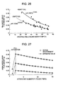
- the unbalanced liquid film amount gradually collapses with the lapse of time (number of cycles) and flows into the cylinder. Desirably, therefore, as shown in Fig. 27 , the unbalanced liquid film amount which collapses in each cycle and flows into the cylinder should be estimated, and the fuel amount should be corrected downward correspondingly.
- an engine control apparatus comprising a means for predictively calculating the amount of the unbalanced liquid film flowing into the cylinder in the next cycle.
- this claim corresponds to claims 2 and 4 and more specifically and expressly states the method of correcting the fuel amount.
- an engine control apparatus comprising a means for correcting the fuel injection amount of the next cycle based on the amount of the fuel in the form of the "balanced liquid film" flowing into the cylinder in the next cycle.
- this claim corresponds to claims 22, 24 and 25, and specifically and expressly states the method of correcting the fuel amount.
- an engine control apparatus comprising a means for controlling, by cylinder, the amount of the fuel remaining in the neighborhood of the intake port or in the intake pipe of each cylinder.
- the fuel injection valve is generally mounted on each cylinder, and therefore, the invention described in claim 21 can be implemented for each cylinder.
- this claim expressly states that the amount of the fuel remaining in the intake pipe (the balanced liquid film amount + the unbalanced liquid film amount) of each cylinder can be controlled independently.
- an engine control apparatus wherein the difference (variation) in the amount of the fuel remaining in the neighborhood of the intake port or in the intake pipe of each cylinder between the cylinders upon lapse of predetermined cycles or a predetermined time is controlled in a predetermined range.
- the amount of the fuel remaining in the intake pipe of each cylinder (the balanced liquid film amount + the unbalanced liquid film amount) can be controlled independently.
- This claim expressly states that the amount of the fuel remaining in the intake pipe, if not required to be varied from one cylinder to another, is desirably controlled uniformly for each cylinder.
- an engine control apparatus comprising a means for detecting the fuel temperature directly or indirectly, a means for determining the balanced liquid film amount in a predetermined fuel property from the fuel temperature, a means for calculating the target combustion fuel amount and a means for injecting, in the first injection session of the engine start period, the fuel in the amount equal to the sum of the balanced liquid film amount and the target combustion fuel amount into each cylinder.
- the amount of the fuel flowing into the cylinder can be controlled as desired by injecting the sum of the balanced liquid film amount and the unbalanced liquid film amount (target cylinder influent fuel amount).
- the balanced liquid film amount is determined primarily from the "fuel temperature and the fuel property" which in turn determines the viscosity at a constant intake flow velocity.
- the balanced liquid film amount is determined based on the particular fuel property. Otherwise, some fuel property is assumed to determine the balanced liquid film amount. From the viewpoint of securing the robustness of the starting performance, however, the fuel property is desirably initialized on heavy side as described in claims 37, 38.
- an engine control apparatus comprising a means for updating and calculating the "balanced liquid film amount in a predetermined fuel property from the fuel temperature" (for each cycle), and a means for correcting the fuel injection amount (in the next and subsequent injection sessions) based on the difference between the "previously calculated balanced liquid film amount” and the "presently calculated balanced liquid film amount”.
- the balanced liquid film amount is dynamically varied depending on the temperature and the fuel property.
- the dynamic variation in the balanced liquid film amount relatively changes the unbalanced liquid film amount also.
- the change in the unbalanced liquid film amount in turn, collapses a part thereof and the amount of the fuel flowing into the cylinder also undergoes a change.
- an engine control apparatus comprising a means for updating the "unbalanced liquid film amount” based on the difference between the "previously calculated balanced liquid film amount” and the "presently calculated balanced liquid film amount", and a means for correcting the fuel injection amount (in the next and subsequent injection sessions) based on the "unbalanced liquid film amount”.
- this claim corresponds to claim 30, and expressly states that the apparatus even includes the means for updating the unbalanced liquid film amount.
- an engine control apparatus comprising a means for determining the various (plural) fuel properties and the corresponding balanced liquid film amount, a means for detecting the actual fuel property directly or indirectly, and a means for determining (switching) the balanced liquid film amount corresponding to the actual fuel property thus detected.
- the balanced liquid film amount is determined based on the particular fuel property. In the case where the actual fuel property is not known so, on the other hand, the balanced liquid film amount is determined based on a some assumed fuel property.
- This claim expressly states that as described with reference to claims 34 to 36, in the case where the fuel property can be detected by some means after starting the engine, the balanced liquid film amount is switched in accordance with the particular fuel property.
- an engine control apparatus wherein the fuel temperature detection means detects the fuel temperature based on at least the atmospheric temperature, the engine intake air temperature or the engine cooling water temperature, or uses the atmospheric temperature, the engine intake air temperature or the engine cooling water temperature in place of the fuel temperature.
- the balanced liquid film amount can be arranged in order by the temperature or the fuel property in Fig. 26 probably by reason of the fact that the viscosity of the fuel is determined primarily by the temperature and the fuel property.
- the fuel temperature is desirably detected directly.
- the fuel temperature may be estimated from the temperature parameter correlated with the fuel temperature, such as the atmospheric temperature, the engine intake air temperature or the engine cooling water temperature.
- the atmospheric temperature, the engine intake air temperature or the engine cooling water temperature may be used as it is without estimating the fuel temperature.
- an engine control apparatus comprising a means for detecting the engine combustion air-fuel ratio directly or indirectly, wherein the fuel property is detected based on the combustion air-fuel ratio.
- the balanced liquid film amount is determined based on the particular fuel property.
- the balanced liquid film amount is determined from some assumed fuel property.
- This claim expressly states that the fuel property is detected based on the combustion air-fuel ratio of the engine after starting.
- the fuel of heavy property for example, the fuel evaporation rate is correspondingly low, and therefore, the air-fuel ratio is larger than the target air-fuel ratio (on lean side). By detecting this, the fuel property can be detected indirectly.
- an engine control apparatus comprising a means for detecting the in-cylinder pressure, the axial torque or the emission air-fuel ratio of the engine directly or indirectly, wherein the combustion air-fuel ratio is detected based on the amount of the fuel and the air supplied to the engine, and the in-cylinder pressure, the axial torque or the emission air-fuel ratio.
- this claim corresponds to claim 34 and is intended to determine the combustion air-fuel ratio indirectly from the in-cylinder pressure, the axial torque or the emission air-fuel ratio of the engine.
- the fuel has a predetermined property
- a realizable combustion air-fuel ratio is determined from the fuel amount and the air amount, while the actual combustion air-fuel ratio is determined from the in-cylinder pressure, the axial torque or the emission air-fuel ratio of the engine. Then, from the difference between these two air-fuel ratios, the fuel property is estimated.
- the in-cylinder pressure and the torque are decreased according as the combustion air-fuel ratio turns lean.
- an engine control apparatus comprising a means for detecting the engine speed change directly or indirectly, wherein the combustion air-fuel ratio is detected based on the amount of the fuel and the air supplied to the engine and the engine speed change.
- this claim corresponds to claim 34 and is intended to determine the combustion air-fuel ratio indirectly from the engine speed change.
- the fuel has a predetermined property
- a realizable combustion air-fuel ratio is determined from the fuel amount and the air amount, while the actual combustion air-fuel ratio is determined from the engine speed change. Then, from the difference between these two air-fuel ratios, the fuel property is estimated.
- the engine speed change increases according as the combustion air-fuel ratio turns lean.
- the balanced liquid film amount is determined based on the particular fuel property.
- the balanced liquid film amount is determined based on some assumed fuel property.
- This item corresponds to item 37, and specifically and expressly describes the fuel property to be initialized.
- an engine control apparatus wherein the "balanced liquid film amount for a predetermined fuel property" is set in such a manner as to increase with the decrease in the "atmospheric temperature, the engine intake air temperature or the engine cooling water temperature”.
- the balanced liquid film amount can be arranged in order by the temperature or the fuel property in Fig. 26 is probably by the reason of the fact that the viscosity of the fuel is determined primarily by the temperature and the fuel property. The viscosity increases with the decrease in temperature. As described in this claim, therefore, the "balanced liquid film amount" is set to increase with the decrease in the "atmospheric temperature, the engine intake air temperature or the engine cooling water temperature”.
- the viscosity increases with the decrease in temperature. More specifically, this claim expressly states that the viscosity is known to be expressed by the Exp function of the fuel temperature (experimental formula).
- the "balanced liquid film amount” proposes an engine control apparatus comprising means for carrying out compensation in accordance with speed of engine intake air or its correlated parameter.
- the amount of the fuel remaining in the intake pipe and the amount of the fuel flowing into the cylinder, included in the fuel liquid film are probably determined by the dynamic balance between the fuel liquid film shearing force due to the intake air amount and the viscosity and the friction force of the fuel liquid film. Therefore, in this specific example, it is intended to clarify that the dynamic balance of the fuel liquid film is determined (compensated) taking into consideration of effect of shearing force due to the intake air.
- an engine control apparatus wherein fuel injection is started before the air intake valve is opened. That is, as has been already, mentioned in previously, as in the prior art, if the fuel injection is carried out in conformity with air intake processes, then the injected fuel is easily flowing into inside the cylinder directly without rendering into balanced liquid film once at air intake pipe inner wall and the surface of air intake valve. In this case, since shearing stress of flow speed of intake air can not be utilized sufficiently, the fuel grain refinement is not sufficiently established to be entered into the cylinder. If the fuel grain size is large, then combustion feature goes bad, and affects both torque performance and exhaust performance. Accordingly in this invention, the fuel injection has to be started at least before opening the air intake valve, utilizing shearing stress of the intake air flow sufficiently, and to propose accelerating fuel grain refinement.
- the amount of the fuel remaining in the neighborhood of the intake port or in the intake pipe of the engine is calculated by being separated into the balanced liquid film amount and the unbalanced liquid film amount in terms of the character thereof.
- the balanced liquid film amount can be determined with higher accuracy by estimation from the fuel property and the fuel temperature (or the temperature correlated thereto). Further, the injection fuel amount is corrected and the amount of the fuel flowing into the cylinder is controlled with high accuracy based on the unbalanced liquid film amount (or the amount of a part of the unbalanced liquid film gradually flowing into the cylinder).
- liquid film fuel is pulverized taking full advantage of the shearing stress due to the intake air flow and then flows into the cylinder.
- the in-cylinder combustion air-fuel ratio at the time of starting the engine can be controlled with higher accuracy, thereby reducing the emission at the time of engine start.
- the amount of the fuel remaining in the neighborhood of the intake port or in the intake pipe of the engine is calculated by being separated into the balanced liquid film amount and the unbalanced liquid film amount.
- the balanced liquid film amount is determined from the fuel property and the fuel temperature (or the temperature correlated thereto), thereby making it possible to estimate the balanced liquid film amount with higher accuracy.
- the injection fuel amount is corrected and the amount of the fuel flowing into the cylinder is controlled with higher accuracy based on the unbalanced liquid film amount.
- the in-cylinder combustion air-fuel ratio at the time of starting the engine is controlled more accurately, thereby reducing the emission at the time of starting the engine.
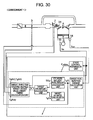
- Fig. 28 is a system diagram showing this embodiment.
- the air from an external source is passed through an air cleaner 1, and through an intake manifold 4 and a collector 5, flows into the cylinder.
- the amount of the influent air is adjusted by an electronic throttle 3, and the influent air amount is detected by an air flow sensor 2.
- An engine speed sensor 15 outputs the signals for each crankshaft rotation angle 1° and each combustion period.
- a water temperature sensor 14 detects the engine cooling water temperature.
- an accelerator pedal angle sensor 13 detects the pedal angle of the accelerator 6 thereby to detect the torque required by the driver.
- the signals of the accelerator pedal angle sensor 13, the air flow sensor 2, the throttle opening degree sensor 17 mounted on the electronic throttle 3, the engine speed sensor 15 and the water temperature sensor 14 are sent to a control unit 16.
- the running condition of the engine is obtained thereby to optimally calculate the main engine operation amounts including the air amount, the fuel injection amount and the ignition timing.
- the fuel injection amount calculated in the control unit 16 is converted into a valve open pulse signal and sent to the fuel injection valve 7. Also, a drive signal is sent to a spark plug 8 in such a manner as to be ignited at the ignition timing calculated by the control unit 16.
- the fuel thus injected is mixed with the air from the intake manifold, and flowing into the cylinder of the engine 9, forms a mixture gas.
- a variable air intake valve 31 is a dynamic variable valve capable of controlling the valve open timing and the valve close timing.
- the mixed air is detonated by the spark generated from the spark plug 8 at a predetermined ignition timing, and the resulting combustion pressure pushes down the piston to constitute the engine power.
- the exhaust gas after detonation is sent into a three-way catalyst 11 through an emission pipe 10. Part of the exhaust gas is recirculated to the intake side through an emission recirculation pipe 18, and controlled by an emission recirculation amount adjust valve 19.
- An A/F sensor 12 is mounted between the engine 9 and the three-way catalyst 11 and has the linear output characteristic with respect to the oxygen concentration of the exhaust gas. The relation between the oxygen concentration of the exhaust gas and the air-fuel ratio is substantially linear, and therefore, the air-fuel ratio can be determined by the A/F sensor 12 for detecting the oxygen concentration.
- the control unit 16 calculates the air-fuel ratio on the upstream side of the three-way catalyst 11 from the signal of the A/F sensor 12, and determines by calculation from the signal of the O 2 sensor 20 downstream of the catalyst whether the air-fuel ratio is rich or lean with respect to the O 2 concentration or the stoichiometric air-fuel ratio on the downstream side of the three-way catalyst. Also, the control unit 16 performs the F/B control operation for correcting the fuel injection amount or the air amount, as required, to optimize the purification efficiency of the three-way catalyst 11 using the output of the A/F sensor 12 and the O 2 sensor 20. Further, the intake air temperature sensor 29 detects the intake air temperature, and the in-cylinder pressure sensor 30 the pressure in the cylinder.
- Fig. 29 shows the internal configuration of the control unit 16.
- the ECU 16 is supplied with the output values of the A/F sensor 12, the throttle opening degree sensor 17, the air flow sensor 2, the engine speed sensor 15, the water temperature sensor 14, the acceleration pedal angle sensor 13, the catalyst-downstream O 2 sensor 20, the intake air temperature sensor 29 and the in-cylinder pressure sensor 30. These signals, after being processed by the input circuit 24 to remove the noises, are sent to the input/output port 25.
- the value of the input port is held in the RAM 23, and arithmetically processed in the CPU 21.
- the control program describing the contents of the arithmetic operation is written beforehand in the ROM 22.
- the value indicating each actuator operation amount calculated in accordance with the control program, after being held in the RAM 23, is sent to the output port 25.
- the spark plug operation signal is set as an on/off signal to turn on by the energization of the the primary coil in the ignition output circuit and turn off by the deenergization thereof.
- the ignition timing is when the signal turns off from on state.
- the spark plug signal set in the output port is amplified to a sufficiently large energy for combustion by the ignition output circuit 26 and supplied to the spark plug.
- the drive signal for the fuel injection valve is set as an on/off signal to turn on when the valve is open and off when the valve is closed, and after being amplified by the fuel injection valve drive circuit 27 to a sufficiently large energy to open the fuel injection valve, sent to the fuel injection valve 7.
- the drive signal for realizing the target opening degree of the electronic throttle 3 is sent to the electronic throttle 3 through the electronic throttle drive circuit 28.
- the drive signal for realizing the open timing and the close timing of the variable intake valve 31, on the other hand, is sent to the variable intake valve 31 through the drive circuit 32.
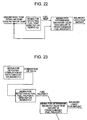
- Fig. 30 is a block diagram showing the control system as a whole configured of the calculation units described below.
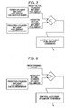
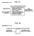
- .Starting control permission unit Fig. 31
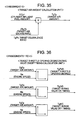
- .Target fuel injection amount calculation unit Fig. 32
- .Cylinder influent fuel injection amount calculation unit Fig. 33
- .Target air-fuel ratio calculation unit Fig. 34
- Fig. 36 Fig. 36
- the “target fuel injection amount calculation unit” calculates the target fuel injection amount (TgTI).
- the “cylinder influent fuel amount calculation unit” predictively calculates the fuel amount (TICy1) injected and actually flowing into the cylinder.
- the “target air-fuel ratio calculation unit” calculates the target air-fuel ratio (TgFA).
- the “target air amount calculation unit” calculates the target air amount (TgTp) in such a manner as to realize the target air-fuel ratio ⁇ TgFA ⁇ based on the cylinder influent fuel amount (TICy1).
- the "target throttle opening degree/intake valve on/off timing calculation unit” calculates the target throttle opening degree (TgTVO) and the target intake valve on/off timing (TgIVC, TgIVO) in such a manner as to realize the target air amount (TgTp).
- the parameters K1, K2, K3 for determining the convergence of the engine speed may be empirically set.
- the processes are executed by the target fuel injection amount calculation unit ( Fig. 32 ), the cylinder influent fuel injection amount calculation unit ( Fig. 33 ), the target air-fuel ratio calculation unit ( Fig. 34 ), the target air amount calculation unit ( Fig. 35 ) and the target throttle opening degree/intake valve on/off timing calculation unit ( Fig. 36 ) described below.
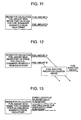
- This calculation unit calculates the target fuel injection amount (TgTI). Specifically, as shown in Fig. 32 , the target fuel injection amount TgTI is determined with reference to a table based on the cooling water temperature (Twn).
- This calculation unit calculates the cylinder influent fuel amount (TICy1). Specifically, as shown in Fig. 33 , the target fuel injection amount (TgTi) is multiplied by the cylinder inflow rate (R_Cy1) to calculate the cylinder influent fuel amount (TICy1).
- the cylinder inflow rate (R_Cy1) is determined with reference to a table based on the cooling water temperature (Twn). The table for determining R_Cy1 is important and should be determined precisely from the test result using the actual device.
- This calculation unit calculates the target equivalent ratio (TgFA) as the inverse of the target air-fuel ratio. Specifically, as shown in Fig. 34 , TgFA is set to TgFA_0. TgFA_0 should generally be set to 1.0.
- This calculation unit calculates the target air amount (TgTp). Specifically, as shown in Fig. 18 , the cylinder influent fuel amount (TICy1) is multiplied by the target air excess rate (1/TgFA) to calculate the target air amount (TgTp).
- This calculation unit calculates TgTVO (target throttle opening degree), TgIVO (target intake valve on timing) and TgIVC (target intake valve off timing). Specifically, as shown in Fig. 36 , TgTVO, TgIVO and TgIVC are determined with reference to each table based on TgTp(n) (target air amount) and Ne (engine speed). The values in each table should be determined theoretically or empirically (experimentally) to secure the operation amount capable of realizing the desired air amount.
- the air amount is controlled in accordance with the fuel actually flowing into the cylinder. Even in the case where the amount of the fuel flowing into the cylinder is extremely reduced at a very low temperature, therefore, the air amount is reduced correspondingly. Therefore, the risk of a misfire which otherwise might be caused by an extreme lean air-fuel ratio and a deteriorated emission are avoided.
- the target air amount is determined directly from the temperature parameter (cooling water temperature) according to the second embodiment.
- Fig. 31 is a system diagram showing this embodiment, and being similar to that of the first embodiment, not described in detail.
- Fig. 32 shows the internal configuration of the control unit 16, and being similar to that of the first embodiment, is not described in detail.
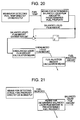
- Fig. 37 is a block diagram showing the control system as a whole configured of the following calculation units:
- the “target air amount calculation unit” calculates the target air amount (TgTp) based on the cooling water temperature (Twn).
- the “target throttle opening degree/intake valve on/off timing calculation unit” calculates the target throttle opening degree (TgTVO) and the target intake valve on/off timing (TgIVC, TgIVO) in such a manner as to realize the target air amount (TgTp).
- This calculation unit calculates the target air amount (TgTp). Specifically, as shown in Fig. 38 , the target air amount (TgTp) is calculated with reference to a table based on the cooling water temperature (Twn).
- the air amount is controlled in accordance with the temperature parameter. Even in the case where the amount of the fuel flowing into the cylinder is extremely reduced at a very low temperature, therefore, the air amount is also reduced in accordance with the temperature. Thus, a misfire which otherwise might be caused by the air-fuel ratio extremely on lean side and the deterioration of the emission are avoided.
- the target air amount is determined based on the amount of the fuel flowing into the cylinder according to the first embodiment, the target air amount is corrected in accordance with the difference between the target fuel injection amount and the amount of the fuel flowing into the cylinder according to the third embodiment.
- Fig. 31 is a system diagram showing this embodiment, and being similar to that of the first embodiment, not described in detail.
- Fig. 32 shows the internal configuration of the control unit 16, and being similar to that of the first embodiment, not described in detail.
- Fig. 39 is a block diagram showing the control system as a whole. As compared with the first embodiment ( Fig. 30 ), the target fuel amount (TgTI) is input to the target air amount calculation unit. The remaining parts of the configuration are identical with those of the first embodiment.
- This calculation unit calculates the target air amount (TgTp). Specifically, a shown in Fig. 40 , the cylinder influent fuel amount (TICy1) is multiplied by the target air excess rate (1/TgFA) to calculate the basic target air amount (TgTpO). The basic target air amount (TgTpO) is multiplied by the corrected target air amount (R_Tp) to determine the target air amount (TgTp). The target air amount (R_Tp) is determined with reference to a table from the fuel control error (e_T1) providing the difference between the target fuel injection amount (TgTI) and the cylinder influent fuel amount (TICy1).
- e_T1 the fuel control error
- the target air amount is calculated based on the fuel injection amount.
- the air amount is corrected and controlled in accordance with the amount of the fuel flowing into the cylinder. Even in the case where the amount of the fuel flowing into the cylinder is extremely reduced at a very low temperature, therefore, the air amount is also reduced in accordance with the temperature. Thus, a misfire which otherwise might be caused by the air-fuel ratio extremely on lean side and the deterioration of emission are avoided.
- the target air amount is determined based on the amount of the fuel flowing into the cylinder. According to the fourth embodiment, however, in the case where the amount of the fuel flowing into the cylinder (the cylinder influent fuel amount) is not larger than a predetermined value, the combustion is judged to have reached its limit and the target air amount is minimized (to zero).
- Fig. 14 is a system diagram showing this embodiment, and being similar to that of the first embodiment, not described in detail.
- Fig. 15 shows the internal configuration of the control unit 16, and being similar to that of the first embodiment, not described in detail.
- Fig. 22 is a block diagram showing the control system as a whole, and being similar to that of the third embodiment, not described in detail.
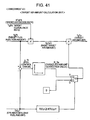
- This calculation unit calculates the target air amount (TgTp). Specifically, as shown in Fig. 41 , the cylinder influent fuel amount (TICy1) is multiplied by the target air excess rate (1/TgFA) to calculate the basic target air amount (TgTpO). In the case where the cylinder influent fuel amount (TICy1) is not smaller than a predetermined value (KTICy1), the basic target air amount (TgTpO) is multiplied by the corrected target air amount (R_Tp) to determine the target air amount (TgTp). The corrected target air amount (R_Tp) is determined with reference to a table from the fuel control error (e_TI) providing the difference between the target fuel injection amount (TgTI) and the cylinder influent fuel amount (TICy1).
- e_TI fuel control error
- the basic air amount (TgTpO) is multiplied by zero so that the target air amount (TgTp) is set to zero.
- Fig. 42 is a block diagram showing the whole control system according to the fifth embodiment, which is configured of the following calculation units:
- the "start control permission unit” determines the start control permission flag (F_sidou) to permit the start control operation.
- the "actual air amount calculation unit” calculates the actual air amount (Tp) per cylinder based on the output signal of the air flow sensor 2, etc.
- the “fuel injection amount calculation unit” calculates the fuel injection amount (TI) based on the actual air amount (Tp) and the cooling water temperature (Twn).
- This calculation unit calculates Tp (actual air amount). Specifically, the equation shown in Fig. 43 is calculated, where Cy1 designates the number of cylinders, and KO is determined according to the specification of the injector (the relation between the fuel injection pulse width and the fuel injection amount).
- This calculation unit calculates the fuel injection amount (TI). Specifically, as shown in Fig. 44 , the following four calculation units are included:
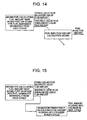
- the target combustion fuel amount calculation unit calculates the target fuel amount (TgTICy1) combusted in the cylinder from the actual in-cylinder air amount (Tp).
- the balanced liquid film amount calculation unit determines the balanced liquid film amount (TI_S) from the cooling water temperature (Twn).
- the unbalanced liquid film amount calculation unit determines the unbalanced liquid film amount (TI_US) from the balanced liquid film amount (TI_S).
- the unbalanced liquid film collapse amount calculation unit determines the collapsed liquid film amount (TI_C) from the unbalanced liquid film amount (TI_US).
- the value of the target combustion fuel amount (TgTICy1) less the collapsed liquid film amount (TI_C) is determined as the final fuel injection amount (TI).
- TgTICy1 target combustion fuel amount less the collapsed liquid film amount (TI_C) is determined as the final fuel injection amount (TI).
- This calculation unit determines the target combustion fuel amount (TgTICy1). Specifically, as shown in Fig. 24 , the actual air amount (Tp) is multiplied by the target equivalence ratio (TgFA) to determine the target combustion fuel amount (TgTICy1).
- the target equivalence ratio (TgFA) designates the combustion equivalence ratio (air-fuel ratio) in the cylinder and should be generally set to 1.0. .Balanced liquid film amount calculation unit ( Fig. 46 )
- This calculation unit determines the balanced liquid film amount (TI_S). Specifically, as shown in Fig. 46 , the balanced liquid film amount (TI_S) is determined with reference to a table from the cooling water temperature (Twn). This table is set as shown in Fig. 26 . Incidentally, in the case where the actual fuel property cannot be detected in advance, some fuel property is assumed for this purpose. In the case where the emission performance is given priority, the table is set with the balanced liquid film amount for the comparatively light fuel property used in the emission verification test. In the case where the starting performance (robustness) is given priority, on the other hand, the table is set with the balanced liquid film amount for the comparatively heavy fuel property.
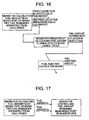
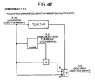
- This calculation unit calculates the unbalanced liquid film amount (TI_US). Specifically, as shown in Fig. 47 , the unbalanced liquid film amount (TI_US) is determined from the difference between the balanced liquid film amount (TI_Sz) in the previous cycle and the balanced liquid film amount (TI_S) in the present cycle. In other words, the unbalanced liquid film amount (TI_US) constitutes the change amount of the balanced liquid film amount during one cycle of the same cylinder. . Unbalanced liquid film collapsed amount calculation unit ( Fig. 48 )
- This calculation unit calculates the collapsed liquid film amount (TI_C). Specifically, as shown in Fig. 48 , assume that the unbalanced liquid film amount (TI_US) is larger than zero, i.e. that an excessive fuel amount exists in the intake pipe. Then, the unbalanced liquid film amount (TI_US) is multiplied by the unbalanced liquid film collapse rate (R_C) to determine the collapsed liquid film amount (TI_C). The unbalanced liquid film collapse rate (R_C) is determined from the unbalanced liquid film amount (TI_US) with reference to a table. This table is set as shown in Fig. 27 .
- the unbalanced liquid film amount (TI_US) is determined as the collapsed liquid film amount (TI_C).
- the injection fuel amount is corrected by the amount equivalent to a gradually collapsed part of the unstable unbalanced liquid film and flowing into the cylinder.
- the fuel amount flowing into the cylinder is controlled with high accuracy in such a manner as to realize the target air-fuel ratio.
- both the emission performance and the starting performance are optimized from the engine starting time.
- the actual fuel property is not specifically detected, and the balanced liquid film amount is set with a predetermined fuel property.
- the fuel property is estimated from the engine speed change after starting, and the balanced liquid film amount is switched based on the result of estimation.
- the system control unit is similar to that of the first embodiment and therefore, not described in detail.
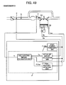
- Fig. 49 is a block diagram showing the control system as a whole. As compared with the fifth embodiment ( Fig. 42 ), the fuel property detection unit is added. The fuel property detection nit determines the fuel property in binary fashion (F_Fuel), and based on the result thereof, changes the fuel injection amount (balanced liquid film amount). The remaining parts of the configuration are identical with those of the fifth embodiment.
- Fig. 43 shows the actual air amount calculation unit which is identical with the corresponding one in the fifth embodiment and therefore not described in detail.
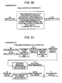
- This detection unit detects (estimates) the actual fuel property. Specifically, as shown in Fig. 50 , the angular acceleration and the angular jerk are detected from the engine speed Ne. In the case where the variance of the angular acceleration or the angular jerk for a predetermined time is not less than a predetermined value, the fuel property is determined as heavy and F_Fuel is set to 1.
- F_Fuel is set to zero.
- the actual combustion air-fuel ratio is determined from the engine speed change and the fuel property is estimated. Incidentally, as long as the heavy fuel is used, the combustion air-fuel ratio is on lean side, and therefore, the engine speed change is increased.
- This calculation unit calculates the fuel injection amount (TI). Specifically, as shown in Fig. 51 , the following four calculation units are included. .Target combustion fuel amount calculation unit ( Fig. 45 ) .Balanced liquid film amount calculation unit ( Fig. 46 ) .Unbalanced liquid film amount calculation unit ( Fig. 47 ) .Unbalanced liquid film collapse amount calculation unit ( Fig. 48 ) The target combustion fuel amount calculation unit calculates the target fuel amount (TgTICy1) combusted in the cylinder from the actual in-cylinder air amount (Tp). The balanced liquid film amount calculation unit determines the balanced liquid film amount (TI_S) from the cooling water temperature (Twn) and the fuel property flag F_Fuel.
- the unbalanced liquid film amount calculation unit determines the unbalanced liquid film amount (TI_US) from the balanced liquid film amount (TI S).
- the unbalanced liquid film collapse amount calculation unit determines the collapsed liquid film amount (TI_C) from the unbalanced liquid film amount (TI_US).
- the value of the target combustion fuel amount (TgTICy1) less the collapsed liquid film amount (TI_C) is determined as the final fuel injection amount (TI).
- TgTICy1 target combustion fuel amount
- TI_C collapsed liquid film amount
- This calculation unit determines the balanced liquid film amount (TI_S). Specifically, as shown in Fig. 52 , the balanced liquid film amount (TI_SH) for the heavy fuel or the balanced liquid film amount (TI_SL) for the light fuel is determined from the cooling water temperature (Twn) with reference to tables. Both tables are set as shown in Fig. 26 . Which balanced liquid film amount is used depends on the value of the fuel property flag (F_Fuel). Incidentally, in the case where the actual fuel property is not detected before starting the engine, some fuel property is assumed and set. In the case where the emission performance is given priority, the balanced liquid film amount for the comparatively light fuel property used for the emission verification test may be the choice.
- F_Fuel fuel property flag
- the balanced liquid film amount for the comparatively heavy fuel property may be employed.
- the balanced liquid film amount for the heavy property is used in the very early stage of the starting period, while after starting the engine, the balanced liquid film amount is forcibly switched to that for the light fuel property regardless of the actual fuel property.
- the air-fuel ratio is optimized, and therefore, the emission is reduced.
- the air-fuel ratio turns lean. Nevertheless, the heavy property is detected by the fuel property detection unit due to the engine speed change and F_Fuel is set to 1. As a result, the balanced liquid film amount for heavy property is automatically restored, thereby optimizing the running performance and the emission performance.
- the target air amount is calculated based on the fuel injection amount.
- the air amount is corrected in accordance with the fuel actually flowing into the cylinder. Even in the case where the fuel amount flowing into the cylinder is extremely reduced at a very low temperature, the corresponding reduction of the air amount makes it possible to avoid both a misfire and a deteriorated emission which otherwise might occur due to the air-fuel ratio on extremely lean side.
- the balanced liquid film amount is automatically switched in accordance with the actual fuel property, and therefore, the unbalanced liquid film amount also changes correspondingly.
- a part of the unbalanced liquid film amount which is collapsed and gradually flows into the cylinder is also optimized in fuel property and the injection fuel amount corrected correspondingly.
- the cylinder influent fuel amount is controlled constantly with high accuracy in such a manner as to realize the target air-fuel ratio. In this way, both the emission performance and the starting performance are optimized from the engine starting time.
- the injection timing is preferably set to end before the intake valve opens in both the fifth and sixth embodiments.
Landscapes
- Engineering & Computer Science (AREA)
- Chemical & Material Sciences (AREA)
- Combustion & Propulsion (AREA)
- Mechanical Engineering (AREA)
- General Engineering & Computer Science (AREA)
- Electrical Control Of Air Or Fuel Supplied To Internal-Combustion Engine (AREA)
- Combined Controls Of Internal Combustion Engines (AREA)
Applications Claiming Priority (2)
| Application Number | Priority Date | Filing Date | Title |
|---|---|---|---|
| JP2007250384A JP2009079557A (ja) | 2007-09-27 | 2007-09-27 | エンジンの制御装置 |
| JP2007250387A JP4474449B2 (ja) | 2007-09-27 | 2007-09-27 | エンジンの制御装置 |
Publications (2)
| Publication Number | Publication Date |
|---|---|
| EP2042711A2 true EP2042711A2 (de) | 2009-04-01 |
| EP2042711A3 EP2042711A3 (de) | 2015-03-11 |
Family
ID=39916351
Family Applications (1)
| Application Number | Title | Priority Date | Filing Date |
|---|---|---|---|
| EP08014717.6A Withdrawn EP2042711A3 (de) | 2007-09-27 | 2008-08-19 | Motorsteuerungsvorrichtung |
Country Status (2)
| Country | Link |
|---|---|
| US (1) | US7809494B2 (de) |
| EP (1) | EP2042711A3 (de) |
Families Citing this family (5)
| Publication number | Priority date | Publication date | Assignee | Title |
|---|---|---|---|---|
| US7881856B2 (en) * | 2008-04-03 | 2011-02-01 | Hitachi, Ltd. | Apparatus for and method of controlling fuel injection of engine |
| US8150604B2 (en) * | 2009-11-02 | 2012-04-03 | GM Global Technology Operations LLC | Method and apparatus for reducing spark plug fouling |
| JP5549267B2 (ja) * | 2010-02-19 | 2014-07-16 | トヨタ自動車株式会社 | 内燃機関の制御装置 |
| US10018143B2 (en) * | 2016-08-19 | 2018-07-10 | Ford Global Technologies, Llc | Methods and system for engine control |
| US10018144B2 (en) * | 2016-08-19 | 2018-07-10 | Ford Global Technologies, Llc | Methods and system for engine control |
Citations (2)
| Publication number | Priority date | Publication date | Assignee | Title |
|---|---|---|---|---|
| JPH02227526A (ja) | 1989-02-28 | 1990-09-10 | Fuji Heavy Ind Ltd | エンジンの燃料噴射制御装置 |
| JPH1054271A (ja) | 1996-08-13 | 1998-02-24 | Nissan Motor Co Ltd | 内燃機関の燃料噴射制御装置 |
Family Cites Families (22)
| Publication number | Priority date | Publication date | Assignee | Title |
|---|---|---|---|---|
| JPS56107925A (en) * | 1980-01-31 | 1981-08-27 | Mikuni Kogyo Co Ltd | Electronically controlled fuel injector for ignited internal combustion engine |
| JPS588239A (ja) * | 1981-07-06 | 1983-01-18 | Toyota Motor Corp | 燃料噴射式エンジンの燃料噴射量制御方法 |
| JPS588238A (ja) * | 1981-07-06 | 1983-01-18 | Toyota Motor Corp | 燃料噴射式エンジンの燃料噴射量制御方法 |
| US4667640A (en) * | 1984-02-01 | 1987-05-26 | Hitachi, Ltd. | Method for controlling fuel injection for engine |
| JPS60201042A (ja) * | 1984-03-27 | 1985-10-11 | Aisan Ind Co Ltd | エンジンの空燃比制御方法 |
| JP2548273B2 (ja) * | 1988-02-17 | 1996-10-30 | 日産自動車株式会社 | 内燃機関の燃料噴射制御装置 |
| JP3503963B2 (ja) * | 1993-09-09 | 2004-03-08 | 株式会社日本自動車部品総合研究所 | 燃料噴射装置 |
| JPH07180580A (ja) | 1993-12-24 | 1995-07-18 | Nissan Motor Co Ltd | エンジンの空燃比制御装置 |
| JPH0953487A (ja) | 1995-08-10 | 1997-02-25 | Honda Motor Co Ltd | 内燃機関の燃料噴射制御装置 |
| JP4707795B2 (ja) * | 2000-04-12 | 2011-06-22 | トヨタ自動車株式会社 | 内燃機関の燃料圧力制御装置 |
| US6360531B1 (en) * | 2000-08-29 | 2002-03-26 | Ford Global Technologies, Inc. | System and method for reducing vehicle emissions |
| JP4742433B2 (ja) * | 2000-09-29 | 2011-08-10 | マツダ株式会社 | エンジンの制御装置 |
| JP3984439B2 (ja) * | 2001-06-19 | 2007-10-03 | 株式会社日立製作所 | 内燃機関の制御装置 |
| US7255093B2 (en) * | 2003-06-30 | 2007-08-14 | Hitachi, Ltd. | Device and method for diagnosing evaporation leak, and control device of internal combustion engine |
| JP2005133601A (ja) | 2003-10-29 | 2005-05-26 | Nissan Motor Co Ltd | エンジンの吸入ガス温度推定装置 |
| JP4464876B2 (ja) * | 2005-07-01 | 2010-05-19 | 日立オートモティブシステムズ株式会社 | エンジンの制御装置 |
| JP4332140B2 (ja) * | 2005-07-15 | 2009-09-16 | トヨタ自動車株式会社 | 内燃機関の制御装置 |
| US7565894B2 (en) * | 2005-09-12 | 2009-07-28 | Hitachi, Ltd. | Fuel injection apparatus for and method of internal combustion engine, and fuel injection valve |
| JP4446084B2 (ja) * | 2006-01-24 | 2010-04-07 | 日立オートモティブシステムズ株式会社 | エンジンの制御装置 |
| JP4359298B2 (ja) * | 2006-09-12 | 2009-11-04 | 株式会社日立製作所 | エンジンの制御装置 |
| US7360512B1 (en) * | 2006-12-22 | 2008-04-22 | Chrysler Llc | Low-thermal-inertia intake ports for port-injected, spark ignition engines and an associated manufacturing method |
| JP4442623B2 (ja) * | 2007-03-14 | 2010-03-31 | 株式会社日立製作所 | エンジンの制御装置 |
-
2008
- 2008-08-19 US US12/194,128 patent/US7809494B2/en not_active Expired - Fee Related
- 2008-08-19 EP EP08014717.6A patent/EP2042711A3/de not_active Withdrawn
Patent Citations (2)
| Publication number | Priority date | Publication date | Assignee | Title |
|---|---|---|---|---|
| JPH02227526A (ja) | 1989-02-28 | 1990-09-10 | Fuji Heavy Ind Ltd | エンジンの燃料噴射制御装置 |
| JPH1054271A (ja) | 1996-08-13 | 1998-02-24 | Nissan Motor Co Ltd | 内燃機関の燃料噴射制御装置 |
Also Published As
| Publication number | Publication date |
|---|---|
| US7809494B2 (en) | 2010-10-05 |
| EP2042711A3 (de) | 2015-03-11 |
| US20090088948A1 (en) | 2009-04-02 |
Similar Documents
| Publication | Publication Date | Title |
|---|---|---|
| US7949459B2 (en) | Control apparatus for vehicle | |
| JP3680491B2 (ja) | 内燃機関の制御装置 | |
| JP4446084B2 (ja) | エンジンの制御装置 | |
| EP1970553A2 (de) | Motorsteuerungsvorrichtung | |
| US7957887B2 (en) | Engine controller | |
| EP2444641B1 (de) | Steuerungsvorrichtung für einen direkteinspritzenden Benzinmotor | |
| US7822536B2 (en) | Start-up control device for internal combustion engine | |
| EP1591650A2 (de) | Vorrichtung und Methode zur Steuerung der Kraftstoffeinspritzung in einer Brennkraftmaschine | |
| JP4477249B2 (ja) | 筒内噴射型内燃機関の制御装置 | |
| US7168238B2 (en) | Method for heating up a catalyst in combustion engines with direct fuel injection | |
| US7809494B2 (en) | Engine control apparatus | |
| JP2001349234A (ja) | 内燃機関の空燃比制御装置 | |
| CN113015848B (zh) | 控制装置 | |
| JP3538003B2 (ja) | 内燃機関の筒内噴射式燃料制御装置 | |
| JP3654010B2 (ja) | 内燃機関の制御装置 | |
| CN102140971A (zh) | 内燃机的空燃比学习控制装置 | |
| JP2003172170A (ja) | 内燃機関のブレーキ負圧制御装置 | |
| JP4927798B2 (ja) | 内燃機関の燃料噴射制御装置 | |
| JP4986895B2 (ja) | エンジンの燃料噴射制御装置 | |
| JP2010168931A (ja) | 火花点火式内燃機関の点火時期制御装置 | |
| EP3075991B1 (de) | Steuerungsvorrichtung für verbrennungsmotor | |
| JP2005337102A (ja) | 内燃機関の燃料噴射制御装置 | |
| JP3564945B2 (ja) | 内燃機関の燃料供給制御装置 | |
| JP4474449B2 (ja) | エンジンの制御装置 | |
| JP2002089338A (ja) | 内燃機関の燃料噴射制御装置 |
Legal Events
| Date | Code | Title | Description |
|---|---|---|---|
| PUAI | Public reference made under article 153(3) epc to a published international application that has entered the european phase |
Free format text: ORIGINAL CODE: 0009012 |
|
| 17P | Request for examination filed |
Effective date: 20090102 |
|
| AK | Designated contracting states |
Kind code of ref document: A2 Designated state(s): AT BE BG CH CY CZ DE DK EE ES FI FR GB GR HR HU IE IS IT LI LT LU LV MC MT NL NO PL PT RO SE SI SK TR |
|
| AX | Request for extension of the european patent |
Extension state: AL BA MK RS |
|
| RIC1 | Information provided on ipc code assigned before grant |
Ipc: F02D 41/04 20060101ALI20141201BHEP Ipc: F02D 41/00 20060101AFI20141201BHEP Ipc: F02D 41/06 20060101ALI20141201BHEP Ipc: F02D 43/00 20060101ALI20141201BHEP |
|
| PUAL | Search report despatched |
Free format text: ORIGINAL CODE: 0009013 |
|
| AK | Designated contracting states |
Kind code of ref document: A3 Designated state(s): AT BE BG CH CY CZ DE DK EE ES FI FR GB GR HR HU IE IS IT LI LT LU LV MC MT NL NO PL PT RO SE SI SK TR |
|
| AX | Request for extension of the european patent |
Extension state: AL BA MK RS |
|
| RIC1 | Information provided on ipc code assigned before grant |
Ipc: F02D 41/06 20060101ALI20150203BHEP Ipc: F02D 41/04 20060101ALI20150203BHEP Ipc: F02D 41/00 20060101AFI20150203BHEP Ipc: F02D 43/00 20060101ALI20150203BHEP |
|
| STAA | Information on the status of an ep patent application or granted ep patent |
Free format text: STATUS: THE APPLICATION HAS BEEN WITHDRAWN |
|
| 18W | Application withdrawn |
Effective date: 20150902 |