EP2042876A1 - Procédé pour la mesure de paramètres dépendant de la vitesse d'un fil - Google Patents
Procédé pour la mesure de paramètres dépendant de la vitesse d'un fil Download PDFInfo
- Publication number
- EP2042876A1 EP2042876A1 EP07019122A EP07019122A EP2042876A1 EP 2042876 A1 EP2042876 A1 EP 2042876A1 EP 07019122 A EP07019122 A EP 07019122A EP 07019122 A EP07019122 A EP 07019122A EP 2042876 A1 EP2042876 A1 EP 2042876A1
- Authority
- EP
- European Patent Office
- Prior art keywords
- yarn
- light
- light wave
- detector
- wave
- Prior art date
- Legal status (The legal status is an assumption and is not a legal conclusion. Google has not performed a legal analysis and makes no representation as to the accuracy of the status listed.)
- Granted
Links
Images


Classifications
-
- G—PHYSICS
- G01—MEASURING; TESTING
- G01S—RADIO DIRECTION-FINDING; RADIO NAVIGATION; DETERMINING DISTANCE OR VELOCITY BY USE OF RADIO WAVES; LOCATING OR PRESENCE-DETECTING BY USE OF THE REFLECTION OR RERADIATION OF RADIO WAVES; ANALOGOUS ARRANGEMENTS USING OTHER WAVES
- G01S17/00—Systems using the reflection or reradiation of electromagnetic waves other than radio waves, e.g. lidar systems
- G01S17/02—Systems using the reflection of electromagnetic waves other than radio waves
- G01S17/50—Systems of measurement based on relative movement of target
- G01S17/58—Velocity or trajectory determination systems; Sense-of-movement determination systems
-
- B—PERFORMING OPERATIONS; TRANSPORTING
- B65—CONVEYING; PACKING; STORING; HANDLING THIN OR FILAMENTARY MATERIAL
- B65H—HANDLING THIN OR FILAMENTARY MATERIAL, e.g. SHEETS, WEBS, CABLES
- B65H61/00—Applications of devices for metering predetermined lengths of running material
- B65H61/005—Applications of devices for metering predetermined lengths of running material for measuring speed of running yarns
-
- B—PERFORMING OPERATIONS; TRANSPORTING
- B65—CONVEYING; PACKING; STORING; HANDLING THIN OR FILAMENTARY MATERIAL
- B65H—HANDLING THIN OR FILAMENTARY MATERIAL, e.g. SHEETS, WEBS, CABLES
- B65H63/00—Warning or safety devices, e.g. automatic fault detectors, stop-motions ; Quality control of the package
- B65H63/06—Warning or safety devices, e.g. automatic fault detectors, stop-motions ; Quality control of the package responsive to presence of irregularities in running material, e.g. for severing the material at irregularities ; Control of the correct working of the yarn cleaner
- B65H63/062—Electronic slub detector
- B65H63/065—Electronic slub detector using photo-electric sensing means, i.e. the defect signal is a variation of light energy
-
- G—PHYSICS
- G01—MEASURING; TESTING
- G01P—MEASURING LINEAR OR ANGULAR SPEED, ACCELERATION, DECELERATION, OR SHOCK; INDICATING PRESENCE, ABSENCE, OR DIRECTION, OF MOVEMENT
- G01P3/00—Measuring linear or angular speed; Measuring differences of linear or angular speeds
- G01P3/36—Devices characterised by the use of optical means, e.g. using infrared, visible, or ultraviolet light
- G01P3/366—Devices characterised by the use of optical means, e.g. using infrared, visible, or ultraviolet light by using diffraction of light
-
- B—PERFORMING OPERATIONS; TRANSPORTING
- B65—CONVEYING; PACKING; STORING; HANDLING THIN OR FILAMENTARY MATERIAL
- B65H—HANDLING THIN OR FILAMENTARY MATERIAL, e.g. SHEETS, WEBS, CABLES
- B65H2701/00—Handled material; Storage means
- B65H2701/30—Handled filamentary material
- B65H2701/31—Textiles threads or artificial strands of filaments
Definitions
- the invention relates to a method for measuring a speed-dependent parameter of a yarn and uses thereof according to the preamble of the independent claims.
- the object is to provide a different measuring method.
- a first light beam is thus thrown onto the yarn and scattered by scattering into at least one first light wave.
- the frequency or wavelength of the first light wave is subject to a Doppler shift due to the yarn movement. If the first light wave is then superimposed with a second light wave, the frequency of the second light wave not being subject to Doppler shift or otherwise, the result is a beat or a periodically changing interference whose frequency is directly dependent on the speed of the yarn is dependent and can be measured.
- LDA Laser Doppler Anemometry
- LDV Laser Doppler Velocimetry
- the light beam on the yarn is split into the first and the second light wave (and, as a rule, further light waves).
- a separate beam splitter is not essential.
- the first and the second light wave are to be selected such that they experience different Doppler shifts as a result of the yarn movement, so that the desired frequency signal is produced at the detector.
- the second light wave originates from light that was not scattered on the yarn.
- the light beam has an elongate cross section when it strikes the yarn, the long cross-sectional axis being substantially perpendicular to the yarn. This reduces the risk of the yarn emerging from the measuring field due to lateral deflections, while the smaller extent of the light field along the yarn longitudinal direction prevents first light waves from arriving at the detector from widely differing directions. This increases the frequency sharpness of the measurement signal.
- the method can be used for a variety of applications. For example, it can be used to measure a wound yarn length and / or the length or position of yarn defects.
- the speed in the present method does not have to be explicitly calculated and output.
- the signal determined by the detector can also be further processed directly without explicit calculation of the speed, for example by counting the signal periods recorded by the detector and thus integrating the speed into a path length. Even in such a case, however, becomes a "speed-dependent Parameter "measured within the meaning of the claims.
- the term “scatter” or “scatter” refers to any type of light deflection, whether diffuse or non-diffuse refraction, or diffuse or non-diffuse reflection.
- an LDA sensor has a coherent light source 1, preferably a semiconductor laser, which generates a light beam 2.
- the light beam 2 strikes a yarn 3 running at a speed v, where it is partially scattered.
- One referred to as “first light wave” 4 Part of the scattered light is scattered at an angle ⁇ and enters a detector 6 arranged in the corresponding direction.
- Another part of the light of the light beam 2 passes unchanged through the surroundings of the yarn 3 and is referred to below as “second light wave” 5.
- the second light wave reaches a deflection mirror 7, from where it is also thrown into the detector 6.
- the frequency of the first light wave 4 is not exactly that of the light beam 2, so that in the region of the superposition of the two light waves 4, 5 at the detector 6 comes to a beating, which as electrical AC signal ( or alternating voltage signal) of a frequency f can be measured.
- the magnitude of the frequency f depends directly on the speed v. It also depends on the angle ⁇ , more precisely on the magnitude of the change in momentum experienced by the photons in the direction of the velocity vector of the yarn 3.
- the corresponding formulas are known to the person skilled in the art and allow the velocity v to be determined directly from the frequency f, given a known geometry of the arrangement and known wavelength of the light of the light source 1.
- the intensity of the first light wave 4 will generally be weaker than that of the second light wave 5, since only a relatively small proportion of the light of the light beam 2 is scattered at all, and of which only a part actually falls onto the detector 6, which only observes a small solid angle , This means that without additional measures, the signal of the detector 6 has a poor contrast, ie it has a high DC component, while the interest actually AC component is much lower. As long as the detector 6 is not saturated comes, this is a child problem.
- the second light wave 5 is attenuated before the superposition with the first light wave 4 to improve the contrast; more precisely - since both light waves between the yarn 3 and the detector 6 are usually attenuated by scattering losses and absorption, eg at intermediate optical components, the second light wave should be attenuated more strongly than the first one before the superposition.
- the additional attenuation of the second light wave should preferably be at least 90%.
- the attenuation of the second light wave 5 may be e.g. take place in that mirror 7 is a partially transmissive mirror which transmits at least 90% of the light output and reflects only 10% or less.
- the two light waves 4 and 7 do not run parallel in their superimposition, which results in that an interference line pattern is generated on the detector 6. Therefore, in order to obtain a clear signal at the frequency f, the detector must be designed to have a dimension of at most about one line width in a direction perpendicular to the interference lines, or an array in the direction perpendicular to the interference lines be provided by sensors whose signals can be evaluated individually.
- Fig. 2 shows a solution in which the first and the second light wave 4 and 5 are made parallel to each other before their superposition, which allows to use a detector with a larger sensitive area.
- the second light wave 5 is thrown from the mirror 7 onto a beam combiner 9, through which the first light wave 4 also passes.
- the beam combiner 9 the two light waves 4 and 5 are superimposed and thrown in parallel onto the detector 6.
- the beam combiner 9 may e.g. be designed as a partially transmitting mirror, which has a greater transmission than reflection, e.g. a transmission of 90% and a reflection of 10%. In this case, it virtually does not weaken the first light wave 4, which passes through it in transmission, while it greatly attenuates the second light wave 5, so that the contrast enhancement described above can be achieved in this way.
- the beam combiner 9 can also be formed by a first surface of a prism, wherein a second surface of the prima forms the mirror 7. It is also conceivable that the beam combiner 9 is formed by a diffraction grating, in particular a Bragg grating.
- FIG. 3 Another execution will be in Fig. 3 shown.
- the first and the second light wave are guided through an imaging optical unit 10, which may for example have the shape of a lens, and which images the area of the yarn illuminated by the light beam 2 onto the plane of the detector 6.
- the advantage of this arrangement is that on the detector 6 those photons from both light waves come together, which originate from the same point of the plane of the yarn 3. This reduces the requirements for the spatial coherence of the laser beam.
- an aperture 11 with two openings 12, 13 is provided between the yarn 3 and the detector 6, with which it can be ensured that only light waves are detected which, starting from the illuminated area of the yarn 3 in two Extend directions:
- the first light wave scattered at angle ⁇ is detected by opening 12, on the other hand, through opening 13, the unscattered second light wave.
- the detector 6 would in the execution after Fig. 6 a mix of one Field variety of signals of different frequencies.
- the second light wave is unscattered light. It can also be formed by scattered light as long as it has experienced a different Doppler shift than the first light wave.
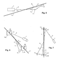
- FIG. 4 A corresponding design is in Fig. 4 shown. This is the same education as those after Fig. 3 , with the difference that the second opening 13 of the mask 11 is arranged such that the second light wave is formed by light which has been scattered at the angle - ⁇ .
- v is the speed of the yarn
- c the speed of light
- f S the frequency of the light of the light source 1.
- ⁇ is the angle between light beam 2 and yarn 3 and ⁇ the scattering angle.
- the angle ⁇ between the light beam 2 and the longitudinal direction of the yarn 3 is selected to be small, for example at most 30 °, in particular at most 10 °. This has the advantage that a relatively long interaction path between yarn 3 and light beam 2 is present, so that more light can be scattered.
- the angle ⁇ 'between the first light wave 4 and the yarn 3 should also be selected to be relatively small, for example at most 30 °, in particular at most 10 °, so that the Doppler shift scatters the frequency of all first light waves received by the detector 6 as little as possible .
- the detector 6 would receive a plurality of first light waves from slightly different directions due to the long interaction path between the beam 2 and yarn 3, resulting in a broad distribution of frequency shifts.
- FIG. 5 An implementation of the concept of Fig. 5 is in 6 and 7 shown. These figures show two guide elements 14, 15, which each have a recess 16 for the lateral guidance of the yarn 3. As can be seen, the light beam 2 is thrown onto the reflective inner side 17 of the first guide element 14 and reflected from there so that it intersects with the yarn 3 at a flat angle ⁇ . In the present example, the (scattered) first light wave 4 is then thrown directly onto the detector 6, while the second light wave 5 (not scattered in the present example) strikes the reflective inner side 17 of the second guide element 15 and thence likewise thrown to the detector 6 becomes.
- the inner sides 17 of the first and the second guide member 14 and 15 are designed to be reflective and shaped so that they throw the incoming light beam or the incoming light wave in the right direction.
- the light source 1 and / or the detector 6 is arranged in or behind the respective guide element 14 or 15 and that the guide elements are configured to be at least partially transparent - in this case, the light beam can also emerge directly from the first guide member 14 and one or both light waves can or can in the second guide element 15 enter so as to get to the detector 6.
- FIG. 8 Another version is in Fig. 8 shown.
- the yarn 3 guided in the guide elements 14, 15 is guided along the surface 19 of a transparent body 18.
- the light source 1 and the detector 6 are arranged on a common carrier 21.
- the light beam 2 emerging from the light source 1 enters the transparent body 18 via a surface 20, with the surface 20 lying opposite the surface 19. At least a portion of the light of the light beam 2 then passes through the surface 19 and strikes the yarn 3, where it is scattered, thus producing the first light wave 4. This is thrown back through the transparent body 18 and strikes the detector 6, where it is superimposed with the second light wave 5.
- the second lightwave 5 can be generated by scattering on one of the surfaces 19, 20 of the transparent body. In the example below Fig. 8 This is done by the fact that the surface 19 facing the yarn 3 is roughened in a region 22, so that it diffuses a part of the light of the light beam 2 substantially diffusely. Part of this diffusely scattered light enters the detector 6 and thus forms the second light wave 5.
- the region 22 is not evenly roughened, but the roughness varies gradually or in several stages along the longitudinal direction of the yarn 3, so that the intensity of the second light wave 5 depends on the relative position of the carrier 21 and the body 18.
- the carrier 21 parallel to the body 18 is shifted to the longitudinal direction of the yarn, as indicated by the arrows 23, thus the brightness of the second light wave 5 can be adjusted to achieve an optimum contrast of the signal at the detector 6.
- light beam 2 is shown as a line.
- its diameter should not be too small, so that the yarn 3 does not escape from the measuring area during lateral movements.
- the extension of the measuring beam in the longitudinal direction of the yarn should be as small as possible in order to make it easier to select for utilization in the detector 6 those light waves which were scattered as precisely as possible at the angle ⁇ .
- the light wave 2 when hitting the yarn 3 has an elongated cross-section 25 whose long cross-sectional axis 26 is substantially perpendicular to the yarn 3.
- the long cross-sectional axis 26 preferably has a length of at least 3 millimeters, so that the yarn does not pass out of the measuring range during typical transverse movements.
- the length of the short cross-sectional axis 27 is advantageously at most 1 mm.
- a light beam 2 of elongated cross section may e.g. be produced by means of cylindrical deflection optics or by refraction on a prism. Corresponding methods are known to the person skilled in the art. It is also conceivable that the light source itself already provides a beam with an oblong cross section, which is e.g. for so-called "edge emitting" semiconductor laser is the case.
- the measure according to FIGS. 9 and 10 is suitable for use in all versions of the device shown here.
- it can also be used in devices in which the light beam is guided in front of the yarn through a beam splitter so as to produce two partial beams, which are crossed again on the yarn, for example.
- semiconductor lasers are particularly suitable as light sources, since they are compact and inexpensive.
- both so-called “single-mode” and “multimode” lasers are suitable.
- Multimode lasers offer the advantage that they can deliver higher power. As long as the frequency spacing of the modes of the "multimode” laser is greater than the maximum achievable Doppler shift in the light waves scattered on the yarn, the measurement can be carried out without further modification of the described embodiments of the measuring device.
- the second light wave should additionally be attenuated in order to obtain a good signal contrast.
- this can be done by means of partially transparent mirrors, but also by means of suitable filters, this can also be a preferably linear polarizing filter 29 are used, as shown as an example in Fig. 3 is drawn. This is arranged so that both light waves 4, 5 pass through it, and it is oriented so that it almost (but not completely) blocks the light of the second light wave and thus attenuates it.
- the influence of the polarization filter on the first light wave is lower, since its light is partially or completely depolarized due to the scattering, or at least turned in its polarization.
- the light of the second light wave 5 in the polarizing filter 29 is much more attenuated than that of the first light wave 4 and the contrast improves.
- a polarizing filter of this type can be used in all embodiments of the device as long as the light from the light source 1 is polarized or polarized with a second polarizing filter.
- FIG. 3 and FIG. 4 the use of a diaphragm and imaging optics has been shown.
- the use of diaphragms and optical elements can also be useful in the other exemplary embodiments and is not based on the exemplary embodiments of FIG FIG. 3 and FIG. 4 limited.
- a color filter 31 can be arranged in all embodiments on the detector 6, as is shown by way of example in FIG Fig. 1 is indicated. This is a bandpass filter which is substantially transparent only to the wavelength of the light of the light source 1.
- the devices shown are not able to determine the sign of the yarn movement without further measures. Since the yarn is e.g. However, in the case of yarn cleaning, it can also be rewound in some cases, a detection of this sign is possible, for example. important for length integration. If the sign of the speed during integration is taken into account, the yarn length as well as the length and position of yarn defects can be correctly determined even if the yarn is driven backwards.
- the sign of the velocity is obtained by shifting one of the two light waves in frequency (eg with an acousto-optic modulator).
- an interference signal with a frequency greater than zero is obtained.
- the frequency shift by the yarn movement can now be done both to higher and lower frequencies, thus the sign of the speed is apparent.
- a phase modulator eg, a Pockels cell, an oscillating mirror, etc.
- the sign can, for example, the evaluation of the detector 6 from an external source, such as the control of the yarn drive, are provided. In Fig. 1 this is by inserting a Pockels cell 30 illustrated in the beam path of the second light wave 5.
- a mechanical modulation of the path length can be performed, for example by the mirror 7 of the embodiment according to Fig. 1 is reciprocated with a piezoelectric element.
- This sign-determination technique can be used on all yarn-based LDA-based processes.
Landscapes
- Engineering & Computer Science (AREA)
- Physics & Mathematics (AREA)
- Electromagnetism (AREA)
- General Physics & Mathematics (AREA)
- Textile Engineering (AREA)
- Quality & Reliability (AREA)
- Power Engineering (AREA)
- Computer Networks & Wireless Communication (AREA)
- Radar, Positioning & Navigation (AREA)
- Remote Sensing (AREA)
- Investigating Materials By The Use Of Optical Means Adapted For Particular Applications (AREA)
- Length Measuring Devices By Optical Means (AREA)
- Optical Radar Systems And Details Thereof (AREA)
Priority Applications (2)
| Application Number | Priority Date | Filing Date | Title |
|---|---|---|---|
| EP20070019122 EP2042876B1 (fr) | 2007-09-28 | 2007-09-28 | Procédé pour la mesure de paramètres dépendant de la vitesse d'un fil |
| JP2008251936A JP5498004B2 (ja) | 2007-09-28 | 2008-09-29 | 糸速度依存パラメータ測定方法 |
Applications Claiming Priority (1)
| Application Number | Priority Date | Filing Date | Title |
|---|---|---|---|
| EP20070019122 EP2042876B1 (fr) | 2007-09-28 | 2007-09-28 | Procédé pour la mesure de paramètres dépendant de la vitesse d'un fil |
Publications (2)
| Publication Number | Publication Date |
|---|---|
| EP2042876A1 true EP2042876A1 (fr) | 2009-04-01 |
| EP2042876B1 EP2042876B1 (fr) | 2012-07-18 |
Family
ID=39205506
Family Applications (1)
| Application Number | Title | Priority Date | Filing Date |
|---|---|---|---|
| EP20070019122 Active EP2042876B1 (fr) | 2007-09-28 | 2007-09-28 | Procédé pour la mesure de paramètres dépendant de la vitesse d'un fil |
Country Status (2)
| Country | Link |
|---|---|
| EP (1) | EP2042876B1 (fr) |
| JP (1) | JP5498004B2 (fr) |
Cited By (2)
| Publication number | Priority date | Publication date | Assignee | Title |
|---|---|---|---|---|
| EP2405287A1 (fr) | 2010-07-08 | 2012-01-11 | Centre National D'etudes Spatiales | Dispositif dé telédétection laser et procédé d'interférometrie |
| CN114442069A (zh) * | 2021-12-27 | 2022-05-06 | 武汉万集光电技术有限公司 | 一种激光探测模组和激光雷达 |
Citations (2)
| Publication number | Priority date | Publication date | Assignee | Title |
|---|---|---|---|---|
| US5064280A (en) | 1987-03-18 | 1991-11-12 | Deutsches Texilforschungs-Zentrum Nord West E.V. | Method of measuring the velocity and/or length of endless webs of textile material and apparatus for carrying out the method |
| EP1521085A1 (fr) * | 2003-09-13 | 2005-04-06 | Saurer GmbH & Co. KG | Procédé et dispositif pour la détermination sans contact de la vitesse d'un fil |
Family Cites Families (5)
| Publication number | Priority date | Publication date | Assignee | Title |
|---|---|---|---|---|
| JPS58197345A (ja) * | 1982-05-10 | 1983-11-17 | 株式会社豊田自動織機製作所 | 流体噴射式織機における緯糸測長方法 |
| JPS5948668A (ja) * | 1982-09-13 | 1984-03-19 | Jiro Koyama | 光フアイバ速度計 |
| JPS6015561A (ja) * | 1983-07-07 | 1985-01-26 | Omron Tateisi Electronics Co | 線状物体の移動速度測定方法 |
| JP3278508B2 (ja) * | 1993-09-27 | 2002-04-30 | 日本板硝子株式会社 | 参照光型レーザドップラ速度計 |
| JP3492012B2 (ja) * | 1995-03-09 | 2004-02-03 | キヤノン株式会社 | 変位情報検出装置 |
-
2007
- 2007-09-28 EP EP20070019122 patent/EP2042876B1/fr active Active
-
2008
- 2008-09-29 JP JP2008251936A patent/JP5498004B2/ja active Active
Patent Citations (2)
| Publication number | Priority date | Publication date | Assignee | Title |
|---|---|---|---|---|
| US5064280A (en) | 1987-03-18 | 1991-11-12 | Deutsches Texilforschungs-Zentrum Nord West E.V. | Method of measuring the velocity and/or length of endless webs of textile material and apparatus for carrying out the method |
| EP1521085A1 (fr) * | 2003-09-13 | 2005-04-06 | Saurer GmbH & Co. KG | Procédé et dispositif pour la détermination sans contact de la vitesse d'un fil |
Non-Patent Citations (2)
| Title |
|---|
| DUBBELDAM G C: "THE CONTACTLESS DETERMINATION OF YARN SPEED WITH A LASER-DOPPLER VELOCITY METER", JOURNAL OF THE TEXTILE INSTITUTE, WOODHEAD PUBLISHING LIMITED, CAMBRIDGESHIRE, GB, vol. 65, 1974, pages 483 - 487, XP001203869, ISSN: 0040-5000 * |
| G. C. DUBBELDAM: "Journal of the Textile Institute", vol. 65, 1974, WOODHEAD PUBL. LTD., article "The contactless determination of yarn speed with a laser-Doppler velocity meter", pages: 483 - 487 |
Cited By (3)
| Publication number | Priority date | Publication date | Assignee | Title |
|---|---|---|---|---|
| EP2405287A1 (fr) | 2010-07-08 | 2012-01-11 | Centre National D'etudes Spatiales | Dispositif dé telédétection laser et procédé d'interférometrie |
| FR2962553A1 (fr) * | 2010-07-08 | 2012-01-13 | Centre Nat Etd Spatiales | Dispositif de teledetection laser et procede d'interferometrie |
| CN114442069A (zh) * | 2021-12-27 | 2022-05-06 | 武汉万集光电技术有限公司 | 一种激光探测模组和激光雷达 |
Also Published As
| Publication number | Publication date |
|---|---|
| JP5498004B2 (ja) | 2014-05-21 |
| JP2009085954A (ja) | 2009-04-23 |
| EP2042876B1 (fr) | 2012-07-18 |
Similar Documents
| Publication | Publication Date | Title |
|---|---|---|
| EP1405037B1 (fr) | Dispositif de mesure optique de distance sur une plage de mesure etendue | |
| EP3324203B1 (fr) | Module de télémétrie laser présentant une analyse de polarisation | |
| EP2724116B1 (fr) | Procédé de mesure de distance par interférométrie pour le mesurage de surface et agencement de mesure correspondant | |
| EP2682709B1 (fr) | Dispositif et procédé de mesure interférométrique d'un objet | |
| DE102013209833B4 (de) | Vibrometer mit einem optischen Interferometer | |
| EP0038950A2 (fr) | Transformateur de mesure avec un guide de lumière comme élément de mesure | |
| EP2520924A1 (fr) | Procédé et agencement de mesure pour l'amélioration de la dissolution de signal dans la spectroscopie d'absorption de gaz | |
| DE2214191B2 (de) | Verfahren zum Bestimmen der Faserorientierung in Papier mit Hilfe vom Papier reflektierten Lichts | |
| DE102011100252A1 (de) | Verfahren und Vorrichtung zur optischen, berührungslosen Schwingungsmessung eines schwingenden Objekts | |
| EP2730947A1 (fr) | Système de mesure LIDAR et procédé de mesure LIDAR | |
| DE102015103139B3 (de) | Verteilte optische Messvorrichtungen und Verfahren zum Ausführen einer Messung | |
| DE2827704C3 (de) | Optische Vorrichtung zur Bestimmung der Lichtaustrittswinkel | |
| EP2002285B1 (fr) | Procede et systeme de creation d'un volume de mesure agrandi en vue de determiner la structure et/ou la vitesse de bobines de fibres textiles par anemometrie laser a effet doppler | |
| EP2856096B1 (fr) | Système optique de mesure avec compensation de polarisation et une méthode correspondante | |
| EP2279397A1 (fr) | Dispositif de mesure de temperature a resolution spatiale | |
| DE1961612A1 (de) | Beruehrungsloser Bewegungs-Messfuehler | |
| DE60036467T2 (de) | Verfahren und vorrichtung zur dopplergeschwindigkeitsmessung | |
| EP0635731A2 (fr) | Méthode et capteur pour déterminer la limite de visibilité dans le brouillard épais | |
| EP1695109A1 (fr) | Dispositif pour mesurer la distance a des objets proches et eloignes | |
| EP2042876B1 (fr) | Procédé pour la mesure de paramètres dépendant de la vitesse d'un fil | |
| DE102012214897B3 (de) | Verfahren zur planaren Bestimmung von Zustandsgrößen einer Fluidströmung sowie Messvorrichtung | |
| DE2936267C2 (fr) | ||
| EP2981809A2 (fr) | Dispositif servant à mesurer la dispersion d'un échantillon | |
| DE3106025C2 (de) | Verfahren und Vorrichtung zur schnellen Messung örtlicher Geschwindigkeitskomponenten in einem Geschwindigkeitsfeld | |
| DE69202780T2 (de) | Verfahren und Vorrichtung für interferometrische Absolutmessungen physikalischer Grössen. |
Legal Events
| Date | Code | Title | Description |
|---|---|---|---|
| PUAI | Public reference made under article 153(3) epc to a published international application that has entered the european phase |
Free format text: ORIGINAL CODE: 0009012 |
|
| AK | Designated contracting states |
Kind code of ref document: A1 Designated state(s): AT BE BG CH CY CZ DE DK EE ES FI FR GB GR HU IE IS IT LI LT LU LV MC MT NL PL PT RO SE SI SK TR |
|
| AX | Request for extension of the european patent |
Extension state: AL BA HR MK RS |
|
| 17P | Request for examination filed |
Effective date: 20090925 |
|
| AKX | Designation fees paid |
Designated state(s): BE CH DE FR IT LI |
|
| GRAP | Despatch of communication of intention to grant a patent |
Free format text: ORIGINAL CODE: EPIDOSNIGR1 |
|
| GRAS | Grant fee paid |
Free format text: ORIGINAL CODE: EPIDOSNIGR3 |
|
| GRAA | (expected) grant |
Free format text: ORIGINAL CODE: 0009210 |
|
| AK | Designated contracting states |
Kind code of ref document: B1 Designated state(s): BE CH DE FR IT LI |
|
| REG | Reference to a national code |
Ref country code: CH Ref legal event code: NV Representative=s name: E. BLUM & CO. AG PATENT- UND MARKENANWAELTE VSP Ref country code: CH Ref legal event code: EP |
|
| REG | Reference to a national code |
Ref country code: DE Ref legal event code: R096 Ref document number: 502007010233 Country of ref document: DE Effective date: 20120913 |
|
| REG | Reference to a national code |
Ref country code: DE Ref legal event code: R082 Ref document number: 502007010233 Country of ref document: DE Representative=s name: SCHUMACHER & WILLSAU PATENTANWALTSGESELLSCHAFT, DE |
|
| PLBE | No opposition filed within time limit |
Free format text: ORIGINAL CODE: 0009261 |
|
| STAA | Information on the status of an ep patent application or granted ep patent |
Free format text: STATUS: NO OPPOSITION FILED WITHIN TIME LIMIT |
|
| 26N | No opposition filed |
Effective date: 20130419 |
|
| REG | Reference to a national code |
Ref country code: DE Ref legal event code: R097 Ref document number: 502007010233 Country of ref document: DE Effective date: 20130419 |
|
| REG | Reference to a national code |
Ref country code: FR Ref legal event code: PLFP Year of fee payment: 10 |
|
| REG | Reference to a national code |
Ref country code: FR Ref legal event code: PLFP Year of fee payment: 11 |
|
| REG | Reference to a national code |
Ref country code: FR Ref legal event code: PLFP Year of fee payment: 12 |
|
| PGFP | Annual fee paid to national office [announced via postgrant information from national office to epo] |
Ref country code: FR Payment date: 20190925 Year of fee payment: 13 |
|
| PG25 | Lapsed in a contracting state [announced via postgrant information from national office to epo] |
Ref country code: FR Free format text: LAPSE BECAUSE OF NON-PAYMENT OF DUE FEES Effective date: 20200930 |
|
| P01 | Opt-out of the competence of the unified patent court (upc) registered |
Effective date: 20230513 |
|
| REG | Reference to a national code |
Ref country code: CH Ref legal event code: U11 Free format text: ST27 STATUS EVENT CODE: U-0-0-U10-U11 (AS PROVIDED BY THE NATIONAL OFFICE) Effective date: 20251001 |
|
| PGFP | Annual fee paid to national office [announced via postgrant information from national office to epo] |
Ref country code: IT Payment date: 20250929 Year of fee payment: 19 |
|
| PGFP | Annual fee paid to national office [announced via postgrant information from national office to epo] |
Ref country code: BE Payment date: 20250925 Year of fee payment: 19 |
|
| PGFP | Annual fee paid to national office [announced via postgrant information from national office to epo] |
Ref country code: DE Payment date: 20251002 Year of fee payment: 19 |
|
| PGFP | Annual fee paid to national office [announced via postgrant information from national office to epo] |
Ref country code: CH Payment date: 20251001 Year of fee payment: 19 |