EP2043237A1 - Betätigungsglied - Google Patents
Betätigungsglied Download PDFInfo
- Publication number
- EP2043237A1 EP2043237A1 EP07767154A EP07767154A EP2043237A1 EP 2043237 A1 EP2043237 A1 EP 2043237A1 EP 07767154 A EP07767154 A EP 07767154A EP 07767154 A EP07767154 A EP 07767154A EP 2043237 A1 EP2043237 A1 EP 2043237A1
- Authority
- EP
- European Patent Office
- Prior art keywords
- frame portion
- axis
- shaft member
- actuator according
- yokes
- Prior art date
- Legal status (The legal status is an assumption and is not a legal conclusion. Google has not performed a legal analysis and makes no representation as to the accuracy of the status listed.)
- Withdrawn
Links
- 238000001514 detection method Methods 0.000 claims abstract description 38
- 230000004907 flux Effects 0.000 claims abstract description 26
- 230000007246 mechanism Effects 0.000 claims description 27
- 230000007935 neutral effect Effects 0.000 claims description 22
- 238000004804 winding Methods 0.000 claims description 9
- 230000008859 change Effects 0.000 claims description 6
- 238000000034 method Methods 0.000 claims description 4
- 230000008569 process Effects 0.000 claims description 2
- 239000000758 substrate Substances 0.000 description 3
- 238000005452 bending Methods 0.000 description 2
- 238000010586 diagram Methods 0.000 description 2
- 238000000465 moulding Methods 0.000 description 2
- 230000035945 sensitivity Effects 0.000 description 2
- XUIMIQQOPSSXEZ-UHFFFAOYSA-N Silicon Chemical compound [Si] XUIMIQQOPSSXEZ-UHFFFAOYSA-N 0.000 description 1
- 239000000853 adhesive Substances 0.000 description 1
- 230000001070 adhesive effect Effects 0.000 description 1
- 230000006870 function Effects 0.000 description 1
- 239000000463 material Substances 0.000 description 1
- 230000002093 peripheral effect Effects 0.000 description 1
- 229920005989 resin Polymers 0.000 description 1
- 239000011347 resin Substances 0.000 description 1
- 230000004044 response Effects 0.000 description 1
- 229910052710 silicon Inorganic materials 0.000 description 1
- 239000010703 silicon Substances 0.000 description 1
- 229920003002 synthetic resin Polymers 0.000 description 1
- 239000000057 synthetic resin Substances 0.000 description 1
Images




Classifications
-
- H—ELECTRICITY
- H02—GENERATION; CONVERSION OR DISTRIBUTION OF ELECTRIC POWER
- H02K—DYNAMO-ELECTRIC MACHINES
- H02K41/00—Propulsion systems in which a rigid body is moved along a path due to dynamo-electric interaction between the body and a magnetic field travelling along the path
- H02K41/02—Linear motors; Sectional motors
- H02K41/035—DC motors; Unipolar motors
- H02K41/0352—Unipolar motors
- H02K41/0354—Lorentz force motors, e.g. voice coil motors
- H02K41/0358—Lorentz force motors, e.g. voice coil motors moving along a curvilinear path
-
- G—PHYSICS
- G02—OPTICS
- G02B—OPTICAL ELEMENTS, SYSTEMS OR APPARATUS
- G02B26/00—Optical devices or arrangements for the control of light using movable or deformable optical elements
- G02B26/08—Optical devices or arrangements for the control of light using movable or deformable optical elements for controlling the direction of light
- G02B26/0816—Optical devices or arrangements for the control of light using movable or deformable optical elements for controlling the direction of light by means of one or more reflecting elements
- G02B26/0833—Optical devices or arrangements for the control of light using movable or deformable optical elements for controlling the direction of light by means of one or more reflecting elements the reflecting element being a micromechanical device, e.g. a MEMS mirror, DMD
- G02B26/085—Optical devices or arrangements for the control of light using movable or deformable optical elements for controlling the direction of light by means of one or more reflecting elements the reflecting element being a micromechanical device, e.g. a MEMS mirror, DMD the reflecting means being moved or deformed by electromagnetic means
-
- G—PHYSICS
- G02—OPTICS
- G02B—OPTICAL ELEMENTS, SYSTEMS OR APPARATUS
- G02B26/00—Optical devices or arrangements for the control of light using movable or deformable optical elements
- G02B26/08—Optical devices or arrangements for the control of light using movable or deformable optical elements for controlling the direction of light
- G02B26/10—Scanning systems
- G02B26/101—Scanning systems with both horizontal and vertical deflecting means, e.g. raster or XY scanners
-
- G—PHYSICS
- G02—OPTICS
- G02B—OPTICAL ELEMENTS, SYSTEMS OR APPARATUS
- G02B26/00—Optical devices or arrangements for the control of light using movable or deformable optical elements
- G02B26/08—Optical devices or arrangements for the control of light using movable or deformable optical elements for controlling the direction of light
- G02B26/10—Scanning systems
- G02B26/105—Scanning systems with one or more pivoting mirrors or galvano-mirrors
Definitions
- the present invention relates to an actuator that sets the tilt angle of a controlled object, such as a mirror, in a desired direction.
- Patent Documents 1 to 3 describe so-called planar galvanomirrors.
- two moving plates are provided inside the outermost peripheral substrate, and each of the moving plates is swingably supported by a pair of torsion bars.
- a driving mechanism for driving a mirror includes coils respectively provided on an outer moving plate and an inner moving plate, and permanent magnets provided around or on the lower side of the coils.
- the galvanomirror in Patent Document 3 is driven by utilizing electrostatic attractive force.
- a mirror part 9 is supported by a substrate 7 via a pair of torsion bars 8 and 8.
- Strain gauges R1 and R2 and strain gauges R3 and R4 are respectively provided near the bases of the torsion bars 8 and 8.
- the tilt angle ⁇ of a mirror surface 10 is controlled while measuring changes in resistance of the strain gauges R1 to R4.
- the present invention is directed to solve the above-described problems of the related art, and an object of the invention is to provide a highly responsive actuator that is suitable for use in a hologram apparatus and the like.
- Another object of the invention is to provide an actuator that can accurately detect the tilt angle of a controlled object with a simple structure.
- An actuator includes a controlled object; a shaft member configured to support the control object; a support member configured to support the shaft member so that the shaft member swings from a neutral position where an axial center of the shaft member coincides with a predetermined neutral axis, in a direction tilting from the neutral axis; a driving mechanism configured to drive the shaft member in the swinging direction; a sensor configured to detect a velocity of the controlled object during swinging; and a control mechanism configured to obtain a feedback signal detected by the sensor and to control a tilt angle of the axial center relative to the neutral axis.
- the actuator according to the present invention can accurately detect the tilt angle of a controlled object with a simple structure. Moreover, since the sensor detects the velocity of the controlled object during swinging, the detection accuracy can be made higher than when the amount of deformation is detected.
- the driving mechanism may include a magnet provided in one of a fixed section and a moving section, driving coils provided in the other of the fixed section and the moving section, and a pair of yokes respectively facing both poles of the magnet.
- the yokes have arms extending sideward and are arranged so that the arms of one of the yokes are movable in the driving coils when the moving section swings.
- the sensor is provided in a gap in which the arms of the yokes face each other.
- the actuator equipped with the driving mechanism is superior in responsivity.
- the senor be formed by a detection coil configured to detect magnetic flux generated by the magnet.
- the detection sensitivity of the sensor can be increased in accordance with the number of turns. Moreover, the angle of the shaft member and the tilt angle of the controlled object can be detected with high accuracy without any influence of temperature changes. For this reason, the actuator has a high detection accuracy and is highly resistant to temperature changes.
- the support member may include an outer frame portion supported by the fixed section; a middle frame portion provided inside the outer frame portion such as to swing around a first axis relative to the outer frame portion; and an inner frame portion provided inside the middle frame portion such as to swing around a second axis orthogonal to the first axis relative to the middle frame portion.
- the outer frame portion and the middle frame portion may be connected by a pair of first torsion bars arranged symmetrically, and the middle frame portion and the inner frame portion may be connected by a pair of second torsion bars spaced 90 degrees apart from the first torsion bars.
- the shaft member extending in a direction orthogonal to both the first axis and the second axis and extending on both sides of the inner frame portion in the orthogonal direction may be insert-molded with the inner frame portion.
- the controlled object may be provided on one side of the shaft member, and the magnet and the yokes, or the driving coils may be provided on the other side.
- the shaft member and the inner frame portion can be connected firmly. For this reason, it is possible to increase the mounting strength of the members mounted on the shaft member, such as the yokes, the magnet, and the controlled object. Therefore, it is possible to increase the driving velocity (swing velocity) of the shaft member, and to make the actuator be superior in responsivity. Moreover, the utilization efficiency of the magnet can be increased, and as a result, the size of the actuator can be reduced.
- the control mechanism may include a detection circuit configured to convert the feedback signal output from the sensor into data; a control unit configured to calculate a driving amount of the controlled object on the basis of the data; and a driver circuit configured to generate a current to be applied to the driving coils of the driving mechanism on the basis of the driving amount.
- the present invention can provide an actuator having a high response speed.
- the actuator of the present invention can detect the tilt angle with high accuracy without any influence of temperature changes. For this reason, it is possible to control the attitude of the controlled object, such as a mirror, with high accuracy. Best Mode for Carrying Out the Invention
- Fig. 1 is a cross-sectional view showing the overall configuration of an actuator according to the present invention
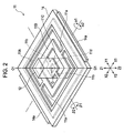
- Fig. 2 is a perspective view of a support member
- Fig. 3 is a perspective view of a magnetic-field generating unit in the actuator.
- the X-, Y-, and Z-axes intersect at right angles, and a point where the X-, Y-, and Z-axes intersect is designated as the origin or a support center point O.
- An axis extending parallel to the Z-axis through the support center point O is designated as a neutral axis O1-O1.
- An actuator 10 shown in Fig. 1 includes a mirror member 20 serving as a controlled object, and freely adjusts and sets a tilt angle (an angle formed between the neutral axis and a mirror 21) ⁇ of the mirror member 20.
- the actuator 10 also includes a support member 11, and a shaft member 12 supported in a manner such as to swing relative to the support member 11.
- the support member 11 is formed by, for example, a thin silicon substrate, and includes an outer frame portion 11A, a middle frame portion 11B, and an inner frame portion 11C each of which is shaped like a rectangular frame.
- the outer frame portion 11A is provided at a position farthest from the neutral axis O1-O1
- the inner frame portion 11C is provided at a position closest to the neutral axis O1-O1.
- the middle frame portion 11B is provided between the outer frame portion 11A and the inner frame portion 11C.
- the outer frame portion 11A and the middle frame portion 11B are connected via a pair of first torsion bars 11a and 11a.
- the middle frame portion 11B and the inner frame portion 11C are connected via a pair of second torsion bars 11b and 11b.
- the first torsion bars 11a and 11a are provided along the X-axis between the outer frame portion 11A and the middle frame portion 11B in a manner such as to be symmetrical with respect to the neutral axis O1-O1 (spaced 180 degrees apart from each other).
- the second torsion bars 11b and 11b are provided along the Y-axis between the middle frame portion 11B and the inner frame portion 11C in a manner such as to be symmetrical with respect to the neutral axis O1-O1 (spaced 180 degrees apart from each other) and to be spaced 90 degrees apart from the first torsion bars around the neutral axis O1-O1.
- the middle frame portion 11B can deform to twist relative to the outer frame portion 11A in directions in which the first torsion bars 11a and 11a serve as the rotation axis (X-axis) (directions ⁇ 1 and ⁇ 2 in Fig. 2 ).
- the inner frame portion 11C can deform to twist relative to the middle frame portion 11B in directions in which the second torsion bars 11b and 11b serve as the rotation axis (Y-axis) (directions ⁇ 1 and ⁇ 2 in Fig. 2 ). That is, the inner frame portion 11C is supported such as to swing on the support center point O in the rotating directions around the X- and Y-axes.
- the shape of the outer frame portion 11A, the middle frame portion 11B, and the inner frame portion 11C is not limited to a rectangular frame shape, and may be other shapes such as a circle.
- the shaft member 12 linearly extends in the Z-axis direction along the neutral axis O1-O1. Since the shaft member 12 is fixed to the inner frame portion 11C of the support member 11, it can swing on the support center point O around the X-axis and the Y-axis serving as the rotation axes via the support member 11. In other words, the shaft member 12 can swing on the support center point O.
- the shaft member 12 can be attached to the support member 11, for example, by an insert molding technique. That is, the shaft member 12 can be attached to the support member 11 by inserting the inner frame portion 11C of the support member 11 in a predetermined mold and pouring and solidifying a resin material in a cavity surrounding the inner frame portion 11C. By forming an opening 11d in the center of the inner frame portion 11C, portions of the shaft member 12 extending from the support member 11 in the Z1-and Z2-directions can be combined.
- the shaft member 12 may be shaped like a prism, as shown in Fig. 2 , or like a cylinder, as shown in Fig. 3 .
- a holding member 14 formed of synthetic resin is provided around the outer frame portion 11A. Convex fixing portions 14a and 14a project from edges of the holding member 14 in the X1- and X2-directions. Similarly to the shaft member 12, the holding member 14 is formed integrally with the outer frame portion 11A by an insert molding technique.
- the actuator 10 includes a fixed member 15 of substantially U-shaped cross section.
- the fixed member 15 includes a base bottom face 15A, inclined bottom faces 15B and 15B formed by slightly obliquely bending the base bottom face 15A, and side wall portions 15C and 15C formed by bending ends of the inclined bottom faces 15B in the Z1-direction. Slots 15a and 15a extending in the Y-direction are respectively provided at the leading ends of the side wall portions 15C and 15C.
- the fixing portions 14a and 14a of the holding member 14 are fitted in the slots 15a and 15a.
- the support member 11, the shaft member 12, and the holding member 14 are thereby attached to the fixed member 15.
- the mirror member 20 serving as a controlled object is provided at the leading end of the shaft member 12 in the Z1-direction in the figure.
- the mirror member 20 includes the above-described mirror 21, and a mirror holding member 22 for holding the mirror 21.
- the leading end of the shaft member 12 in the Z1-direction is fixed to the center of a surface of the mirror holding member 22 facing in the Z2-direction.
- the mirror holding member 22 be formed integrally with the shaft member 12.
- the mirror holding member 22 may be formed by a separate process, and be fixed to the leading end of the shaft member 12, for example, with an adhesive or by screwing.
- a magnetic-field generating unit 30A that forms part of a driving mechanism 30 is provided at the other end (in the Z2-direciton) of the shaft member 12.
- the magnetic-field generating unit 30A includes a first yoke 31, a second yoke 32, and a magnet M.
- the first yoke 31 and the second yoke 32 have the same shape.
- the first yoke 31 includes a main body 31A substantially shaped like a square, and four arms 31a, 31a, 31a, and 31a extending sideward from four side faces of the main body 31A, respectively.
- the four arms 31a, 31a, 31a, and 31a do not extend perpendicularly to the neutral axis O1-O1, but obliquely extend such as to slightly tilt in one direction (Z1-direction).
- the second yoke 32 includes a main body 32A substantially shaped like a square, and four arms 32a, 32a, 32a, and 32a obliquely extending from four side faces of the main body 31A, respectively.
- the magnet M is clamped between the main body 31A of the first yoke 31 and the main body 32A of the second yoke 32.
- the four arms 31a of the first yoke 31 face the four arms 32a of the second yoke 32 in parallel, and gaps g are provided therebetween.
- the mirror member 20 is provided at one end of the shaft member 12, and the magnetic-field generating unit 30A is provided at the other end thereof.
- the shaft member 12 is supported such as to swing relative to the support member 11.
- the shaft member 12 is supported such as to swing on the support center point O around the X-axis (in the directions ⁇ 1 and ⁇ 2) and around the Y-axis (in the directions ⁇ 1 and ⁇ 2).
- driving coils C (individually denoted by C1, C2, C3, and C4) are provided on the inclined bottom faces 15B of the fixed member 15.
- the driving coil C1 is provided on the X1-side
- the driving coil C2 is provided on the X2-side
- the driving coil C3 is provided on the Y1-side
- the driving coil C4 is provided on the Y2-side.
- illustration of the driving coil C3 is omitted.
- Each of the driving coils C is formed by winding a wire in the form of a cylinder (circular cylinder or rectangular cylinder).
- An opening Ca extends through the center of each driving coil C in a direction orthogonal to the winding direction.
- the four arms 32a, 32a, 32a, and 32a of the second yoke 32 are movably inserted in the openings Ca of the driving coils C1, C2, C3, and C4.
- the driving coils C1, C2, C3, and C4 are partly located in the four gaps g provided between the four arms 31a and the four arms 32a, respectively.
- the driving coils C1, C2, C3, and C4 are cylindrical, as described above, the number of turns can be made more than that of a planar coil. For this reason, a great electromagnetic force can be easily generated, and the responsivity of the actuator 10 can be enhanced.
- the magnet M is magnetized as the south pole on the Z1-side, and as the north pole on the Z2-side, as shown in Fig. 1 .
- magnetic fluxes ⁇ form magnetic paths in the order "the north pole - the main body 32A of the second yoke 32 - the four arms 32a of the second yoke 32 - the four gaps g (driving coils C1, C2, C3, and C4) - the four arms 31a of the first yoke 31 - the main body 31A of the first yoke 31 - the south pole".
- the magnetic fluxes ⁇ interlink with currents flowing through the wires that form the driving coils C1, C2, C3, and C4.
- a velocity sensor 41 is attached to each of the driving coils C1, C2, C3, and C4 provided in the gaps g.
- the velocity sensor 41 is formed as a detection coil (planar coil) 41a in which a wire is wound in a planar or ring shape.
- the winding direction of the wire in the detection coil 41a is orthogonal to the driving coils C1, C2, C3, and C4.
- the winding direction of the wire in the detection coil 41a is orthogonal to the direction of the magnetic flux ⁇ passing through the gap g.
- the velocity sensor 41 can detect the magnetic flux ⁇ passing through the detection coil 41a.
- the driving coils C1, C2, C3, and C4 generate magnetic fluxes passing through the openings Ca.
- the magnetic fluxes of the driving coils C1, C2, C3, and C4 are parallel to the winding direction of the detection coils 41a.
- the velocity sensors 41 rarely detect the magnetic fluxes generated by the driving coils C1, C2, C3, and C4.
- the magnetic-field generating unit 30A and the driving coils C1, C2, C3, and C4 constitute the driving mechanism 30 that generates a driving force for swinging the controlled object (mirror member 20).
- the mirror member 20 serving as the control object and the magnetic-field generating unit 30A that forms the moving section be balanced in weight on the support center point O.
- an axial center O1'-O1' of the shaft member 12 coincides with the neutral axis O1-O1 (neutral position state).
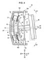
- Fig. 4 is a cross-sectional view showing an operating state of the actuator
- Fig. 5 shows a detecting operation of the velocity sensor
- Fig. 5A shows a state before the arm moves
- Fig. 5B shows a state after the arm has moved
- Fig. 6 is a block diagram showing the configuration of a control mechanism in the actuator
- Fig. 7 is a flowchart illustrating control of the actuator.
- the electromagnetic force is generated in the driving coil C2 in a direction F2 orthogonal to the winding direction of the driving coil C2 or the opposite direction F2'.
- an electromagnetic force in the F1-direction is generated in the driving coil C1
- an electromagnetic force in the F2-direction is generated in the driving coil C2.
- an electromagnetic force in the F1'-direction is generated in the driving coil C1
- an electromagnetic force in the F2'-direction is generated in the driving coil C2.
- the driving coil C1 and the driving coil C2 are fixed to the fixed member 15. For this reason, even when electromagnetic forces are generated, the driving coil C1 and the driving coil C2 themselves do not move. Hence, the electromagnetic forces react on the magnetic-field generating unit 30A. For example, when an electromagnetic force in the F1'-direction is generated in the driving coil C1, a reacting force acts in the F1-direction opposite thereto. Similarly, when an electromagnetic force in the F2'-direction is generated in the driving coil C2, a reacting force acts in the F2-direction opposite thereto.
- the shaft member 12 can be swung (tilted) on the support center point O in the rotating direction ( ⁇ 1- or ⁇ 2-direction) by controlling the directions of currents to be passed through the driving coils C1 and C2.
- the shaft member 12 can be swung (tilted) in the direction ⁇ 1 or ⁇ 2 shown in Fig. 2 in accordance with the directions of currents to be passed through the driving coil C3 and the driving coil C4.
- the orientation of the mirror member 20 provided at one end of the shaft member 12 can be changed freely.
- the detection coil 41a detects an electromotive force (feedback signal) e that follows the Fleming's right-hand rule, from the physical quantity, that is, the velocity of the controlled object during swinging.
- the output electromotive force e is proportional to the velocity component v. That is, the detection coil 41a functions as a velocity sensor.
- the above-described point also applies to the detection coils 41a provided in the other driving coils C2, C3, and C4.
- the detection coils 41a By using the detection coils 41a, the velocity components v in the directions can be detected.
- the driving coil C1 and the driving coil C2 are arranged such as to be symmetrical with respect to the neutral axis O1-O1. For this reason, the electromotive force e detected by the velocity sensor 41 at the driving coil C1 and the electromotive force e detected by the velocity sensor 41 at the driving coil C2 have the same amplitude in theory.
- the velocity sensor 41 may be provided at only one of the driving coils. That is, in the above-described embodiment, at least two velocity sensors 41 may be provided, for example, one velocity sensor 41 may be provided at each of the driving coil C1 and the driving coil C3.
- the velocity sensor 41 at the driving coil C3 detects the velocity in the direction ⁇ 1 or ⁇ 2 around the X-axis direction.
- the velocity sensor 41 at the driving coil C1 detects the velocity in the direction ⁇ 1 or ⁇ 2 around the Y-axis direction.
- the control mechanism of the actuator 10 mainly includes a control unit 51, a driver circuit (current driving circuit) 51 for applying current to the driving coils C1, C2, C3, and C4, and a detection circuit (voltage detection circuit) 53 for detecting feedback signals from the velocity sensors 41.
- the control unit 51 includes a computing unit (e.g., a CPU and a memory) that plays a main role in computation.
- the detection circuit 53 converts voltages (electromotive forces e; velocity components) output from the detection coils 41a of the velocity sensors 41 into data (digital values), and feeds the data back to the control unit 51.
- the output (electromotive force e) from the detection coil 41a means a velocity component (physical quantity) v in the direction of the tangent to a circle having a predetermined radius R provided when the shaft member 12 swings (turns) on the support center point O. Therefore, the control unit 51 obtains the velocity components v from the feedback signals, and performs a predetermined calculation using the velocity components v. For example, the control unit 51 sequentially calculates the moving amount of the mirror 21 serving as the controlled object. Further, the control unit 51 calculates the driving amount for driving the mirror 21 from a set value and the moving amount, and gives driving data corresponding to the driving amount to the driver circuit 52. Alternatively, the control unit 51 may obtain the tilt angles ⁇ from the neutral axis O1-O1 in the directions, and may calculate the driving data from a set value and the present tilt angles ⁇ .
- the driver circuit 52 On the basis of the driving data, the driver circuit 52 generates currents (driving signals) to be applied to the driving coils C1, C2, C3, and C4. On the basis of the currents applied to the driving coils C1, C2, C3, and C4, the above-described electromotive forces are generated, the shaft member 12 is swung, and the tilt angle of the mirror 21 serving as the controlled object is changed to a desired tilt angle ⁇ .
- the twisting forces of the first torsion bars 11a and 11a and the second torsion bars 11b and 11b that form the support member 11 increase as the twisting angle increases.
- the twisting forces act as resistance force on the driving force for swinging the shaft member 12. For this reason, when the tilt of the mirror 21 is variably controlled, it is necessary to apply, to the driving coils C1 to C4, currents that increase as the twisting angle increases.
- the operating time that is, the time taken until the control unit receives feedback signals from the velocity sensors 41 and gives instructions to the driver circuit 52, and the driver circuit 52 applies currents to the driving coils C1 to C4 according to the instructions and generates driving data on the basis of the feedback signals (velocity components) detected by the velocity sensors 41 is of the order of nanoseconds.
- the tilt angle ⁇ of the mirror 21 can be quickly set with the control mechanism using the velocity sensors 41. That is, the hologram apparatus is superior in responsivity.
- the control unit 51 can set and store data on optimal currents for the driving coils C1 to C4 beforehand in accordance with predetermined angles. This allows the tilt angle of the mirror 21 to be changed more accurately and quickly.
- Attitude control performed using the read data information may be used auxiliarily or confirmatively.
- the present invention is not limited thereto, and is also applicable to a single-axis actuator capable of driving only around the X-axis or the Y-axis.
- the actuator can be used as an actuator for an antenna that changes the orientation of the antenna.
- the actuator in the above-described embodiment is of a moving magnet type in which the driving coils are provided in the fixed section and the magnetic-field generating unit including the magnet and the yokes is provided in the moving section
- the present invention is not limited thereto. That is, the actuator may be of a moving coil type in which a magnetic-field generating unit including a magnet and yokes is provided in the fixed section and driving coils are provided in the moving section.
- the detection coils capable of detecting the velocity are used as sensors for detecting the tilt angle ⁇ of the controlled object in the above-described embodiment, the present invention is not limited thereto.
- changes in magnetic flux may be detected with magnetic detection elements such as a Hall element or a magnetoresistive element (e.g., an AMR, a GMR, or an MR).
Landscapes
- Physics & Mathematics (AREA)
- General Physics & Mathematics (AREA)
- Optics & Photonics (AREA)
- Electromagnetism (AREA)
- Engineering & Computer Science (AREA)
- Chemical & Material Sciences (AREA)
- Combustion & Propulsion (AREA)
- Power Engineering (AREA)
- Reciprocating, Oscillating Or Vibrating Motors (AREA)
- Mechanical Light Control Or Optical Switches (AREA)
- Mechanical Optical Scanning Systems (AREA)
Applications Claiming Priority (2)
| Application Number | Priority Date | Filing Date | Title |
|---|---|---|---|
| JP2006174110 | 2006-06-23 | ||
| PCT/JP2007/062264 WO2007148664A1 (ja) | 2006-06-23 | 2007-06-19 | アクチュエータ |
Publications (2)
| Publication Number | Publication Date |
|---|---|
| EP2043237A1 true EP2043237A1 (de) | 2009-04-01 |
| EP2043237A4 EP2043237A4 (de) | 2017-06-07 |
Family
ID=38833406
Family Applications (1)
| Application Number | Title | Priority Date | Filing Date |
|---|---|---|---|
| EP07767154.3A Withdrawn EP2043237A4 (de) | 2006-06-23 | 2007-06-19 | Betätigungsglied |
Country Status (4)
| Country | Link |
|---|---|
| US (1) | US7868490B2 (de) |
| EP (1) | EP2043237A4 (de) |
| JP (1) | JP4790802B2 (de) |
| WO (1) | WO2007148664A1 (de) |
Cited By (1)
| Publication number | Priority date | Publication date | Assignee | Title |
|---|---|---|---|---|
| WO2018171846A1 (de) * | 2017-03-24 | 2018-09-27 | Blickfeld GmbH | Winkelmagnetfeldsensor für scanner |
Families Citing this family (4)
| Publication number | Priority date | Publication date | Assignee | Title |
|---|---|---|---|---|
| TWI369232B (en) * | 2009-03-09 | 2012-08-01 | Ind Tech Res Inst | Impact force feedback device and interactive system using the same |
| CA2831197A1 (en) * | 2013-10-28 | 2015-04-28 | Patrick Mcfadden | Electric linear actuator |
| JPWO2020110747A1 (ja) | 2018-11-30 | 2021-09-27 | パイオニア株式会社 | 駆動装置 |
| JP7360263B2 (ja) | 2019-07-18 | 2023-10-12 | Thk株式会社 | アクチュエータ |
Family Cites Families (10)
| Publication number | Priority date | Publication date | Assignee | Title |
|---|---|---|---|---|
| JPH05119280A (ja) | 1991-10-24 | 1993-05-18 | Ricoh Co Ltd | ガルバノミラー |
| JPH06178524A (ja) * | 1992-12-04 | 1994-06-24 | Hitachi Metals Ltd | ボイスコイル型モータ |
| JPH08334723A (ja) | 1995-06-06 | 1996-12-17 | Olympus Optical Co Ltd | 光偏向素子 |
| JPH11183490A (ja) * | 1997-12-19 | 1999-07-09 | Fuji Xerox Co Ltd | 光偏向装置 |
| JP2001075031A (ja) * | 1999-09-08 | 2001-03-23 | Sony Corp | 光軸補正装置 |
| JP2002296518A (ja) | 2001-03-29 | 2002-10-09 | Miyota Kk | ガルバノミラーチップおよびその製造方法 |
| JP3420577B2 (ja) * | 2001-07-18 | 2003-06-23 | シャープ株式会社 | リニアアクチュエータ及びリニアアクチュエータを用いたレンズ駆動装置 |
| JP2004020956A (ja) * | 2002-06-17 | 2004-01-22 | Sumitomo Heavy Ind Ltd | ビームスキャナ |
| US7009752B1 (en) * | 2003-01-21 | 2006-03-07 | Lockheed Martin Corporation | Actively-supported multi-degree of freedom steerable mirror apparatus and method |
| TWI252961B (en) * | 2004-08-04 | 2006-04-11 | Delta Electronics Inc | Magnetic dynamic diaphragm controller |
-
2007
- 2007-06-19 WO PCT/JP2007/062264 patent/WO2007148664A1/ja not_active Ceased
- 2007-06-19 EP EP07767154.3A patent/EP2043237A4/de not_active Withdrawn
- 2007-06-19 JP JP2008522458A patent/JP4790802B2/ja not_active Expired - Fee Related
-
2008
- 2008-12-12 US US12/333,888 patent/US7868490B2/en not_active Expired - Fee Related
Non-Patent Citations (1)
| Title |
|---|
| See references of WO2007148664A1 * |
Cited By (1)
| Publication number | Priority date | Publication date | Assignee | Title |
|---|---|---|---|---|
| WO2018171846A1 (de) * | 2017-03-24 | 2018-09-27 | Blickfeld GmbH | Winkelmagnetfeldsensor für scanner |
Also Published As
| Publication number | Publication date |
|---|---|
| EP2043237A4 (de) | 2017-06-07 |
| WO2007148664A1 (ja) | 2007-12-27 |
| JPWO2007148664A1 (ja) | 2009-11-19 |
| JP4790802B2 (ja) | 2011-10-12 |
| US7868490B2 (en) | 2011-01-11 |
| US20090091194A1 (en) | 2009-04-09 |
Similar Documents
| Publication | Publication Date | Title |
|---|---|---|
| US6215299B1 (en) | Linear position sensor having a permanent magnet that is shaped and magnetized to have a flux field providing a sensor output that varies linearly between opposite end points of relative linear movement between the magnet and sensor | |
| US5859733A (en) | Apparatus for detecting and displaying position of a lens on an optical axis | |
| JP4907770B2 (ja) | フラックスゲート・センサを使用する位置エンコーダ | |
| EP1610142B1 (de) | Memsstromsensor mit magnetisch-zu-mechanischer Umwandlung und Bezugsbestandteilen | |
| JP5306384B2 (ja) | モータ | |
| US7868490B2 (en) | Actuator | |
| JP2017519995A (ja) | センサ | |
| JP2010091565A (ja) | 微小電気機械システム(mems)力平行加速度計 | |
| KR101397273B1 (ko) | 자기력 센서 | |
| TW200921070A (en) | Detecting device and measuring apparatus | |
| CN119986939A (zh) | 光学元件驱动机构 | |
| JP2023543867A5 (de) | ||
| JP5151958B2 (ja) | 位置検出装置およびそれを備えた回転直動モータ | |
| US4829844A (en) | Power assist handle | |
| CN104181330B (zh) | 加速度传感器 | |
| WO2008081371A1 (en) | Sensor | |
| EP0398150A2 (de) | Stellungsfühler | |
| US20240021351A1 (en) | Adjustment device, adjustment system and computer program product | |
| JPH07128132A (ja) | 振動測定用のセンサー | |
| JP3451829B2 (ja) | 加速度センサ | |
| JPH095016A (ja) | 磁気センサ | |
| JP2000065853A (ja) | 振動又は加速度の検出装置 | |
| JP3438416B2 (ja) | 直線送り装置 | |
| JP2000009529A (ja) | 変位計 | |
| JPH02151770A (ja) | 磁気式加速度センサおよびその製造方法 |
Legal Events
| Date | Code | Title | Description |
|---|---|---|---|
| PUAI | Public reference made under article 153(3) epc to a published international application that has entered the european phase |
Free format text: ORIGINAL CODE: 0009012 |
|
| 17P | Request for examination filed |
Effective date: 20090122 |
|
| AK | Designated contracting states |
Kind code of ref document: A1 Designated state(s): AT BE BG CH CY CZ DE DK EE ES FI FR GB GR HU IE IS IT LI LT LU LV MC MT NL PL PT RO SE SI SK TR |
|
| AX | Request for extension of the european patent |
Extension state: AL BA HR MK RS |
|
| RBV | Designated contracting states (corrected) |
Designated state(s): DE FR GB |
|
| DAX | Request for extension of the european patent (deleted) | ||
| STAA | Information on the status of an ep patent application or granted ep patent |
Free format text: STATUS: EXAMINATION IS IN PROGRESS |
|
| RA4 | Supplementary search report drawn up and despatched (corrected) |
Effective date: 20170511 |
|
| RIC1 | Information provided on ipc code assigned before grant |
Ipc: G03H 1/22 20060101ALI20170504BHEP Ipc: G02B 26/10 20060101ALI20170504BHEP Ipc: H02K 33/00 20060101AFI20170504BHEP |
|
| 17Q | First examination report despatched |
Effective date: 20170522 |
|
| STAA | Information on the status of an ep patent application or granted ep patent |
Free format text: STATUS: THE APPLICATION IS DEEMED TO BE WITHDRAWN |
|
| 18D | Application deemed to be withdrawn |
Effective date: 20171003 |