EP2045631A1 - Film mince pour film réfléchissant ou semi-réfléchissant, cible de pulvérisation et support d'enregistrement optique - Google Patents
Film mince pour film réfléchissant ou semi-réfléchissant, cible de pulvérisation et support d'enregistrement optique Download PDFInfo
- Publication number
- EP2045631A1 EP2045631A1 EP06832812A EP06832812A EP2045631A1 EP 2045631 A1 EP2045631 A1 EP 2045631A1 EP 06832812 A EP06832812 A EP 06832812A EP 06832812 A EP06832812 A EP 06832812A EP 2045631 A1 EP2045631 A1 EP 2045631A1
- Authority
- EP
- European Patent Office
- Prior art keywords
- reflection film
- thin film
- silver
- semi
- target
- Prior art date
- Legal status (The legal status is an assumption and is not a legal conclusion. Google has not performed a legal analysis and makes no representation as to the accuracy of the status listed.)
- Granted
Links
Images

Classifications
-
- G—PHYSICS
- G02—OPTICS
- G02B—OPTICAL ELEMENTS, SYSTEMS OR APPARATUS
- G02B5/00—Optical elements other than lenses
- G02B5/08—Mirrors
-
- C—CHEMISTRY; METALLURGY
- C23—COATING METALLIC MATERIAL; COATING MATERIAL WITH METALLIC MATERIAL; CHEMICAL SURFACE TREATMENT; DIFFUSION TREATMENT OF METALLIC MATERIAL; COATING BY VACUUM EVAPORATION, BY SPUTTERING, BY ION IMPLANTATION OR BY CHEMICAL VAPOUR DEPOSITION, IN GENERAL; INHIBITING CORROSION OF METALLIC MATERIAL OR INCRUSTATION IN GENERAL
- C23C—COATING METALLIC MATERIAL; COATING MATERIAL WITH METALLIC MATERIAL; SURFACE TREATMENT OF METALLIC MATERIAL BY DIFFUSION INTO THE SURFACE, BY CHEMICAL CONVERSION OR SUBSTITUTION; COATING BY VACUUM EVAPORATION, BY SPUTTERING, BY ION IMPLANTATION OR BY CHEMICAL VAPOUR DEPOSITION, IN GENERAL
- C23C14/00—Coating by vacuum evaporation, by sputtering or by ion implantation of the coating forming material
- C23C14/22—Coating by vacuum evaporation, by sputtering or by ion implantation of the coating forming material characterised by the process of coating
- C23C14/34—Sputtering
- C23C14/3407—Cathode assembly for sputtering apparatus, e.g. Target
- C23C14/3414—Metallurgical or chemical aspects of target preparation, e.g. casting, powder metallurgy
-
- C—CHEMISTRY; METALLURGY
- C23—COATING METALLIC MATERIAL; COATING MATERIAL WITH METALLIC MATERIAL; CHEMICAL SURFACE TREATMENT; DIFFUSION TREATMENT OF METALLIC MATERIAL; COATING BY VACUUM EVAPORATION, BY SPUTTERING, BY ION IMPLANTATION OR BY CHEMICAL VAPOUR DEPOSITION, IN GENERAL; INHIBITING CORROSION OF METALLIC MATERIAL OR INCRUSTATION IN GENERAL
- C23C—COATING METALLIC MATERIAL; COATING MATERIAL WITH METALLIC MATERIAL; SURFACE TREATMENT OF METALLIC MATERIAL BY DIFFUSION INTO THE SURFACE, BY CHEMICAL CONVERSION OR SUBSTITUTION; COATING BY VACUUM EVAPORATION, BY SPUTTERING, BY ION IMPLANTATION OR BY CHEMICAL VAPOUR DEPOSITION, IN GENERAL
- C23C14/00—Coating by vacuum evaporation, by sputtering or by ion implantation of the coating forming material
- C23C14/06—Coating by vacuum evaporation, by sputtering or by ion implantation of the coating forming material characterised by the coating material
- C23C14/0688—Cermets, e.g. mixtures of metal and one or more of carbides, nitrides, oxides or borides
-
- G02B1/105—
-
- G—PHYSICS
- G02—OPTICS
- G02B—OPTICAL ELEMENTS, SYSTEMS OR APPARATUS
- G02B1/00—Optical elements characterised by the material of which they are made; Optical coatings for optical elements
- G02B1/10—Optical coatings produced by application to, or surface treatment of, optical elements
- G02B1/14—Protective coatings, e.g. hard coatings
-
- G—PHYSICS
- G11—INFORMATION STORAGE
- G11B—INFORMATION STORAGE BASED ON RELATIVE MOVEMENT BETWEEN RECORD CARRIER AND TRANSDUCER
- G11B7/00—Recording or reproducing by optical means, e.g. recording using a thermal beam of optical radiation by modifying optical properties or the physical structure, reproducing using an optical beam at lower power by sensing optical properties; Record carriers therefor
- G11B7/24—Record carriers characterised by shape, structure or physical properties, or by the selection of the material
- G11B7/241—Record carriers characterised by shape, structure or physical properties, or by the selection of the material characterised by the selection of the material
- G11B7/252—Record carriers characterised by shape, structure or physical properties, or by the selection of the material characterised by the selection of the material of layers other than recording layers
- G11B7/258—Record carriers characterised by shape, structure or physical properties, or by the selection of the material characterised by the selection of the material of layers other than recording layers of reflective layers
- G11B7/259—Record carriers characterised by shape, structure or physical properties, or by the selection of the material characterised by the selection of the material of layers other than recording layers of reflective layers based on silver
-
- G—PHYSICS
- G02—OPTICS
- G02B—OPTICAL ELEMENTS, SYSTEMS OR APPARATUS
- G02B5/00—Optical elements other than lenses
- G02B5/08—Mirrors
- G02B5/0808—Mirrors having a single reflecting layer
-
- Y—GENERAL TAGGING OF NEW TECHNOLOGICAL DEVELOPMENTS; GENERAL TAGGING OF CROSS-SECTIONAL TECHNOLOGIES SPANNING OVER SEVERAL SECTIONS OF THE IPC; TECHNICAL SUBJECTS COVERED BY FORMER USPC CROSS-REFERENCE ART COLLECTIONS [XRACs] AND DIGESTS
- Y10—TECHNICAL SUBJECTS COVERED BY FORMER USPC
- Y10T—TECHNICAL SUBJECTS COVERED BY FORMER US CLASSIFICATION
- Y10T428/00—Stock material or miscellaneous articles
- Y10T428/21—Circular sheet or circular blank
Definitions
- the present invention relates to a thin film useful as a reflection film or a semi-transparent reflection film used in an optical recording medium, a display and the like.
- the present invention particularly relates to the thin film which shows reflectance that does not decrease even after it is used for a long period of time, and the optical recording medium having the thin film as the reflection film or the semi-transparent reflection film.
- An optical recording medium such as a CD-R/RW, a DVD-R/RW/RAM and a Blue-Ray disk
- a display device such as a liquid crystal display and an organic luminescent display
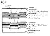
- Fig. 1 shows a structure of an HD-DVD (one-sided, dual-layer rewritable disk) which has been developed in recent years, as an example of the optical recording medium.
- the optical recording medium has a multilayer structure comprising the reflection film in addition to a recording layer which plays a predominant role of the function of the optical recording medium, a protective layer and a thermal diffusion layer.
- silver has a problem of changing the color to black through being corroded to decrease its reflectance, because of being inferior in corrosion resistance.
- the factor of causing corrosion in a reflection film is, for instance, an organic dye applied in a recording layer of an optical recording medium, though it depends on an applied medium and device. Then, the reflection film shows lower reflectance since it is corroded by the organic dye after a long term of service.
- the reflection film in a display device may cause corrosion due to the atmospheric moisture. For this reason, a thin film made from a silver alloy has been developed which contains various elements in a silver matrix, so as to solve the problem of the corrosion resistance of silver.
- Patent Document 1 discloses a silver alloy containing 0.5 to 10 atom% ruthenium and 0.1 to 10 atom% aluminum
- Patent Document 2 discloses a silver alloy containing 0.5 to 4.9 atom% palladium
- Patent Document 3 and Patent Document 4 disclose a silver alloy containing Ca, V and Nb, and the like.
- a thin film composed of the above described silver alloy shows a certain improvement effect on corrosion resistance. Then, the problem of corrosion should have been solved, but an optical recording medium using a thin film formed from the silver alloy still can not completely inhibit a recording error caused by the degradation of the reflection film. On the other hand, a material more excellent in reflectance-keeping characteristics than ever has been required along with requirement to a further improvement of a recording speed and recording density toward future.
- the present invention is directed at providing a thin film that is applied to a reflection film and to a semi-transparent reflection film, which compose an optical recording medium, a display and the like, and that can function without decreasing its reflectance even after a long period of use; and a production method therefor.
- the present inventors have made an extensive research on a mechanism how a silver thin film degrades its reflection characteristics, and found that the degradation is caused not only by simple corrosion (blackening) but also by a phenomenon that silver atoms migrate while the thin film is heated.
- the phenomenon of migration of silver atoms is a phenomenon that silver atoms composing a flat thin film right after it is formed migrate toward an energetically stable state through being driven by a given environmental condition. At this time, the silver atoms migrate not only in a planar direction but also in a three-dimensional direction in many cases, and as a result, cohere into a polygonal shape close to a sphere.
- an optical recording medium employing such a thin film for a reflection film reflects less light toward a sensor of an optical recording device in a sensor axis direction, and consequently causes an error in the recording medium.
- a conventional silver alloy has a little effect of inhibiting a migration phenomenon of silver atoms. This is because a metal atom alloyed with silver should have some function of inhibiting the migration of silver atoms.
- the conventional silver alloy mainly has aimed at improving corrosion resistance, and accordingly all the alloyed components have not been effective for inhibiting the migration of the silver atoms.
- the present inventors studied a technique for inhibiting silver atoms from migrating in a thin film; examined silver alloys having the effect; found that it is effective as a further improved remedy for inhibiting the silver atoms from migrating to disperse a silver compound phase in silver or a silver alloy, and thus formed thin film acquires superior reflectance-keeping characteristics; and attained the present invention.
- the present invention provides a thin film for a reflection film or a semi-transparent reflection film, which has a phase of at least one compound selected from the group consisting of a nitride, an oxide, a composite oxide, a nitroxide, a carbide, a sulfide, a chloride, a silicide (excluding silicon), a fluoride, a boride, a hydride, a phosphide, a selenide and a telluride of aluminum, magnesium, tin, zinc, indium, titanium, zirconium, manganese and silicon, dispersed in a matrix formed of silver or a silver alloy.
- a nitride an oxide, a composite oxide, a nitroxide, a carbide, a sulfide, a chloride, a silicide (excluding silicon), a fluoride, a boride, a hydride, a phosphide, a selenide and
- the thin film according to the present invention may include any of silver compounds among nitride, an oxide, a composite oxide, a nitroxide, carbide, sulfide, chloride, silicide, fluoride, boride, hydride, phosphide, selenide and telluride of silver, as a compound phase.
- Specific examples of the silver compound are shown in Table 2.
- the silver compounds include not only intentionally formed compounds but also the compounds which are concurrently produced when the above described compound phase of aluminum or the like is formed, as is described later in an item on a method for producing the thin film.
- the compound phase formed of the silver compound also acts to inhibit silver atoms in the thin film from migrating, similarly as the compound phase of aluminum or the like does.
- this silver compound phase includes a compound in a stoichiometrically non-equilibrium state as well.
- the thin film according to the present invention may include a chemical compound of a particular metal other than the above described metal (aluminum and the like, silver), as a compound phase.
- the thin film may contain, in a dispersed state, at least one compound selected from the group consisting of a nitride, an oxide, a composite oxide, a nitroxide, a carbide, a sulfide, a chloride, a silicide, a fluoride, a boride, a hydride, a phosphide, a selenide and a telluride of gallium, palladium or copper.
- Specific examples of the compound phase of such a particular metal are shown in Table 3.
- the content of the above described compound phase is preferably 0.001 to 2.5 wt.%.
- the compound phase in an amount of 0.001 wt.% or more is necessary for sufficiently inhibiting the migration of silver atoms.
- the upper limit is set at 2.5 wt.% because the silver compound contained above the upper limit imparts an insufficient initial reflectance to the thin film.
- the content of the compound phase is preferably 0.001 to 1.0 wt.%, and further preferably is 0.001 to 0.5 wt.%. As the content of the compound phase increases, the effect of inhibiting reflectance reduction increases but the reflectance tends to decrease. It is preferable to control the content of the compound phase according to an application field within the above described range.
- the content of the compound phase is based on the total weight of the thin film (the total weight of the matrix and the compound phase).
- the content of the compound phase shall be the total content of those compounds.
- the compound phases are preferably dispersed in a particulate form composed of many molecules of the compound, but are not always limited to this form.
- the compound phase may be formed of molecules of at least one chemical compound.
- the size of the compound phase is preferably controlled into 1/10 or less of a thickness of a thin film. For instance, when the thickness of the thin film is set at 1,000 ⁇ , the compound phase preferably has a size of 100 ⁇ or smaller, and when the thickness of the thin film is set at 120 ⁇ , the dispersing compound phase preferably has a size of 12 A or smaller.
- the matrix of the thin film according to the present invention is pure silver or silver alloy.
- the effect of inhibiting the migration of silver atoms is mainly made by a compound phase, but alloyed components also possess an effect to be reckoned with.
- the thin film acquires excellent reflectance-keeping characteristics due to the action of the compound phase. For this reason, in the present invention, any of pure silver and a silver alloy shall be used as the matrix.
- the alloy is preferably an alloy formed from silver and at least any one element of aluminum, magnesium, tin, zinc, indium, titanium, zirconium, manganese and silicon. These elements are metallic elements composing the compound phase shown at the beginning of the above description, but also form alloy components by being alloyed with silver to inhibit the migration phenomenon of silver atoms.
- a silver alloy as the matrix may include a metal other than aluminum.
- a silver alloy as the matrix may employ at least one element among gallium, palladium, and copper, as an alloying element. This is because these metallic elements are those which compose the compound phase shown in the third group of the above description, and also shows not a little effect of inhibiting the migration phenomenon of silver atoms by being alloyed with silver.
- the concentration of a metal to be alloyed with silver is preferably 0.01 to 10 wt.%. This is because when the concentration is less than 0.01 wt.%, the alloying effect is negligible, and when the concentration exceeds 10 wt.%, the thin film aggravates its reflectance. Furthermore, the concentration is more preferably 0.01 to 5 wt.%, and further preferably is 0.01 to 3.5 wt.%. The above described concentration of the metal is based on a weight of the silver alloy of the matrix.
- a reflection film according to the present invention has preferably a thickness of 120 to 1,200 ⁇ when applied to an optical recording medium, a display and the like.
- a sputtering technique As a production method.
- the technique includes two directions which is described below.
- a first technique is a method of using a target having a structure and a composition similar to a thin film to be produced, specifically, is a method of using a sputtering target prepared by dispersing a phase of at least one compound selected from the group consisting of a nitride, an oxide, a composite oxide, a nitroxide, a carbide, a sulfide, a chloride, a silicide (excluding silicon), a fluoride, a boride, a hydride, a phosphide, a selenide and a telluride of aluminum, magnesium, tin, zinc, indium, titanium, zirconium, manganese and silicon, in a matrix formed of silver or a silver alloy.
- a sputtering target prepared by dispersing a phase of at least one compound selected from the group consisting of a nitride, an oxide, a composite oxide, a nitroxide, a carbide, a
- the method can produce the thin film with the use of one plate of target, accordingly can produce the thin film by a sputtering technique with a form of arranging the target so as to face a substrate, which is ordinarily employed when producing a reflection film, and consequently produce the thin film with adequate productivity.
- a sputtering technique with a form of arranging the target so as to face a substrate, which is ordinarily employed when producing a reflection film, and consequently produce the thin film with adequate productivity.
- a first form is an internally chemically-combined type target.
- the internally chemically-combined type target is prepared by heat-treating a raw material made from silver (pure silver) or a silver alloy in an atmosphere of high-pressure oxygen gas, nitrogen gas or the like to chemically combine a metal to be alloyed with silver or the silver alloy in the interior partially with oxygen or nitrogen or the like into the oxide, the nitride or the like.
- the raw material described in the above may have a tabular shape close to the shape of the target, or may be prepared by employing a granular material, chemically combining the interior with other elements for the raw material, and then compression-molding the resultant granular material.
- a second form to be used is a sintered target.
- the sintered target is prepared by mixing a powder of silver (pure silver) or a silver alloy with a powder made from a compound to be dispersed in the target in accordance with a desired composition, compressing and molding the mixed powder, and sintering the compact.
- the sintered target is useful when the above described internally chemically-combined type target is difficult to produce such as in the case when the target can hardly contain a sufficient concentration of a compound phase, and is preferable for producing a thin film, for instance, in which aluminum oxide, manganese oxide, or magnesium nitride is dispersed as a compound phase.
- a third form is an embedded type target.
- the embedded type target is prepared by embedding a small piece (with a cylindrical shape, a spherical shape or the like though the shape is not limited) of a chemical compound to be dispersed, into a region to be consumed by sputtering in a target made from pure silver or a silver alloy.
- the above described internally chemically-combined type target and sintered target have a composition and a structure microscopically close to those of a thin film to be produced, as is shown in Fig. 2(a) , whereas this target has those macroscopically close to the thin film to be produced, as is shown in Fig. 2(b) .
- the composition of the thin film to be produced can be controlled by changing a diameter of the small piece of the compound to be embedded; positions of the small pieces to be arranged, the number of the pieces and a sputtering rate.
- a content of a compound phase is preferably controlled so as to have the same composition as a thin film to be produced.
- the content of the chemical compound is preferably 0.001 to 2.5 wt.%, more preferably is 0.001 to 1.0 wt.%, and further preferably is 0.001 to 0.5 wt.%.
- the size of the compound phase in these targets is not limited in particular, and may be the same molecular level as in the thin film to be produced, or may be a millimeter order as in the embedded type target. This is because whatever the sizes of the compound phase, a compound is sputtered in a molecule unit when being sputtered, and the formed thin film acquires the desired composition.
- a silver alloy as the matrix is preferably an alloy which contains silver and at least any one element of aluminum, magnesium, tin, zinc, indium, titanium, zirconium, manganese and silicon, or further at least any one element of gallium, palladium and copper.
- concentration of a metal element to be alloyed is preferably 0.01 to 10 wt.%, more preferably is 0.01 to 5 wt.%, and further preferably is 0.01 to 3.5 wt.%.
- the second directionality for producing a thin film according to the present invention is to improve a sputtering method.
- the method employs mainly a general target of pure silver or a silver alloy as a target, and does not employ a special target as is used in the above described first directionality.
- a special target as is used in the above described first directionality.
- a first technique is a co-sputtering technique with the use of a plurality of targets.
- the technique is a method of simultaneously sputtering a plurality of targets made from a chemical compound and a metal having the same composition as in a phase composing a thin film.
- the thin film having a compound phase formed of titanium carbide (TiC) dispersed in silver or a silver alloy can be produced by using two targets of a pure silver target or a silver alloy target, and a titanium carbide target, placing them together in a chamber, and simultaneously sputtering the two targets.
- TiC titanium carbide
- the method is useful when it is difficult to prepare a special target such as the above described internally chemically-combined type target.
- the reactive sputtering is a technique of adding a reactive gas such as oxygen and nitrogen into an atmosphere for sputtering, sputtering the target, oxidizing or nitriding the whole or a part of a particle sputtered from a target, and forming a thin film from the oxidized or nitrided particle.
- the reactive sputtering technique is a useful method when a chemical compound to be dispersed in the thin film is expensive, is hardly available or is difficult to be chemically prepared.
- the reactive sputtering technique may be singularly used, but may be used in combination with another technique.
- the above described special integral target specifically, using an internally chemically-combined target, a sintered target and an embedded type target
- it is possible to increase a content of a chemical compound in the thin film by introducing a reactive gas into an atmosphere in a sputtering apparatus.
- a target and a thin film were produced not only by using these targets, but also by using a co-sputtering technique and a reactive sputtering technique.
- compositions of a target and a thin film are expressed hereafter, they are expressed in the form of matrix/compound phase, and in the form, a front part of "/" represents a matrix and a rear part represents a compound phase.
- concentration of an alloying element is expressed by weight% with respect to the silver alloy of the matrix.
- Ag-3.0 wt.% Ga-2.0 wt.% Cu/1.0 wt.% Si 3 N 4 of sample No. 21, means that the thin film (target) has 1.0 wt.% Si 3 N 4 dispersed in the matrix of a silver alloy having a composition of Ag-3.0 wt.% Ga-2.0 wt.% Cu, with respect to a total weight of the thin film (target).
- An internally chemically-combined type target was prepared by the steps of: preparing 5.0 kg of a granular raw material of Ag-0.33 wt.% Al alloy with a particle diameter of 1.0 to 3.0 mm; charging it into a high-pressure reaction pot; sufficiently replacing the air inside the pot with nitrogen gas; increasing a pressure and a temperature respectively to 0.8 MPa of a nitrogen gas pressure and 800°C; keeping the pot in the state for 48 hours for subjecting Al to internal nitriding; then, slowly cooling the internally nitrided alloy grains; taking them out; charging them into a die; high-pressure-extruding them at 750°C into an integrated compact; forging the compact; rolling the forged compact into a plate (with dimension of 160 mm ⁇ 160 mm ⁇ 6 mm); and cutting the plate into a sputtering target having a standard size (with a diameter of 152 mm (6 inches) and a thickness of 5 mm).
- the target had a composition of Ag/0.5 w
- an Ag/ 2.5 wt.% ZnO (sample No. 3) target was prepared as an internally chemically-combined type target.
- the target of the sample No. 3 was produced by using an Ag-2.0 wt.% Zn alloy as a raw material, and oxidizing the interior with an oxygen gas pressure of 0.4 MPa and at 750°C for a holding period of 10 hours.
- targets corresponding to samples No. 2, 4 to 8, and 6 to 9 were prepared by changing a silver alloy and an internally chemically-combining condition.
- a sintered type target was produced by the steps of: preparing a powder of an Ag-5.0wt.% Pd alloy and a powder of titanium nitride both with particle sizes of 50 to 100 ⁇ m; weighing the powders so as to form a desired composition; sufficiently mixing them; then charging the mixture into a die made from carbon; pressing the mixture to form a compact; then sintering the compact in a vacuum sintering furnace at 750°C for 8 hours to form a sintered integral compact; forging and rolling the compact into a plate for further improving denseness; and then cutting the plate into a sputtering target with the same standard size as described previously.
- the target had a composition of Ag-5.0 wt.% Pd/2.0 wt.% TiN.
- the target corresponds to the sample No. 18 which is described later.
- targets corresponding to samples No. 9 to 20 were prepared as a sintered type target, by changing the types of a silver alloy powder and a compound powder.
- An embedded type target was produced by the steps of: preparing a disc with a standard size (with a diameter of 152 mm (6 inches) and a thickness of 5 mm) made from an Ag-3.0 wt.% Ga-2.0 wt.% Cu alloy; perforating 6 round holes with a diameter of 1.05 mm at regular spaces so as to form a circle with a diameter of 80 mm; inserting round bars made from silicon oxide (Si 3 N 4 ) with a diameter of 1.0 mm and a length of 5 mm into the round holes; and calking perimeters of the round bars so that the round bars might not drop off and could be fixed.
- the target had a composition of Ag-3.0 wt.% Ga-2.0 wt.% Cu/1.0 wt.% Si 3 N 4 .
- the target corresponds to the sample No. 21 which is described later.
- targets corresponding to samples No. 22, 23 were prepared as an embedded type target, by changing an alloy composition of a disc and a composition and the number of round bars to be embedded.
- a thin film was produced by using the above-described various targets, and by employing a co-sputtering technique and a reactive sputtering technique.
- the thin film was formed on a polycarbonate substrate for DVD.
- the substrate (with a diameter of 120 mm and a sheet thickness of 0.6 mm) was produced through an injection molding machine provided with a stamper, in which a pre-format pattern was formed.
- a reflection film was formed into a film thickness of 120 ⁇ with each method.
- a thin film was evaluated by evaluating characteristics of a DVD medium which was prepared by forming a thin film on a polycarbonate substrate in the above described way.
- the evaluation was conducted by the steps of: measuring a jitter value, a PI error, a PO failure and a reflectance of the DVD medium in an initial state after it was prepared, with the use of an optical disc evaluation instrument (optical disc evaluation instrument ODU-1000 made by Pulstec Industrial Co., Ltd.); and confirming whether they were within a range of DVD standards.
- optical disc evaluation instrument optical disc evaluation instrument ODU-1000 made by Pulstec Industrial Co., Ltd.
- a front part of "/" represents silver or a silver alloy of a matrix, and a rear part represents a compound phase.
- *2 Methods for producing thin films are described below. a: internally chemically-combined type target was used. b: sintering type target was used. c: embedded type target was used. d: co-sputtering e: reactive sputtering
- a recording medium provided with a reflection film having a compound phase dispersed therein according to the present invention showed less occurrences of a PI error and a PO failure and further a lower decreasing rate of a reflectance than a DVD medium provided with a reflection film formed from pure silver.
- the DVD medium provided with the reflection film formed from pure silver was not recognized by a recording device after a humidification test, and became unusable.
- a thin film according to the present invention minimizes the deterioration of the reflectance even after a long period of use, and can prolong the life of various devices which use the thin film as a reflection film, such as an optical recording medium and a display.
- the reflection film according to the present invention has also reflectance-keeping characteristics which are little affected by a wavelength of incident light.
- the wavelength of light for a light source for recording is being shortened such as in the development of an HD-DVD using a blue laser beam, in a field of an optical recording medium.
- the present invention can cope with such a technology.
- the thin film according to the present invention provides merits of reducing the number of errors and extending the life, when applied to the optical recording medium, for instance.
- a reflection film has only to have a function of reflecting light, and includes a film having optical transparency. Accordingly, the thin film according to the present invention can be also applied to a semi-reflection/semi-transparent film used in an optical recording medium.
Landscapes
- Chemical & Material Sciences (AREA)
- Physics & Mathematics (AREA)
- Materials Engineering (AREA)
- Chemical Kinetics & Catalysis (AREA)
- Engineering & Computer Science (AREA)
- Mechanical Engineering (AREA)
- Metallurgy (AREA)
- Organic Chemistry (AREA)
- Optics & Photonics (AREA)
- General Physics & Mathematics (AREA)
- Physical Vapour Deposition (AREA)
- Manufacturing Optical Record Carriers (AREA)
- Optical Elements Other Than Lenses (AREA)
- Optical Record Carriers And Manufacture Thereof (AREA)
Applications Claiming Priority (1)
| Application Number | Priority Date | Filing Date | Title |
|---|---|---|---|
| PCT/JP2006/322933 WO2008059582A1 (fr) | 2006-11-17 | 2006-11-17 | Film mince pour film réfléchissant ou semi-réfléchissant, cible de pulvérisation et support d'enregistrement optique |
Publications (3)
| Publication Number | Publication Date |
|---|---|
| EP2045631A1 true EP2045631A1 (fr) | 2009-04-08 |
| EP2045631A4 EP2045631A4 (fr) | 2010-02-17 |
| EP2045631B1 EP2045631B1 (fr) | 2012-04-25 |
Family
ID=39401396
Family Applications (1)
| Application Number | Title | Priority Date | Filing Date |
|---|---|---|---|
| EP06832812A Not-in-force EP2045631B1 (fr) | 2006-11-17 | 2006-11-17 | Film mince pour film de réflexion ou film semi-transparent de réflexion, cible de pulvérisation et support d'enregistrement optique |
Country Status (6)
| Country | Link |
|---|---|
| US (1) | US7951442B2 (fr) |
| EP (1) | EP2045631B1 (fr) |
| JP (1) | JPWO2008059582A1 (fr) |
| KR (1) | KR101279663B1 (fr) |
| CN (1) | CN101449184B (fr) |
| WO (1) | WO2008059582A1 (fr) |
Cited By (1)
| Publication number | Priority date | Publication date | Assignee | Title |
|---|---|---|---|---|
| EP3196334A4 (fr) * | 2015-02-27 | 2018-04-11 | Mitsubishi Materials Corporation | Cible de pulvérisation d'un alliage en ag et procédé de fabrication d'un film en un alliage en ag |
Families Citing this family (10)
| Publication number | Priority date | Publication date | Assignee | Title |
|---|---|---|---|---|
| JP5410286B2 (ja) * | 2006-10-20 | 2014-02-05 | エフ・イ−・アイ・カンパニー | S/temのサンプルを作成する方法およびサンプル構造 |
| EP2271879B1 (fr) | 2007-12-21 | 2018-02-21 | AGC Glass Europe | Réflecteur d'énergie solaire |
| JP5580972B2 (ja) * | 2008-06-06 | 2014-08-27 | デクセリアルズ株式会社 | スパッタリング複合ターゲット |
| CN101676436B (zh) * | 2008-09-19 | 2012-08-22 | 深圳富泰宏精密工业有限公司 | 表面处理方法 |
| US9103000B2 (en) * | 2009-11-25 | 2015-08-11 | Zetta Research and Development LLC—AQT Series | Low melting point sputter targets for chalcogenide photovoltaic applications and methods of manufacturing the same |
| JP5485091B2 (ja) * | 2010-09-16 | 2014-05-07 | ソニー株式会社 | 光記録媒体 |
| CN102454901B (zh) * | 2010-10-29 | 2014-05-07 | 陈波 | 高亮度通体发光新型led照明灯管 |
| CN107502867B (zh) * | 2017-08-22 | 2019-05-28 | 江阴恩特莱特镀膜科技有限公司 | 一种用于热反射玻璃行业旋转硅银靶材及其制备方法 |
| CN108281159A (zh) * | 2017-12-28 | 2018-07-13 | 广东紫晶信息存储技术股份有限公司 | 一种长效光数据存储介质合金材料及制备方法 |
| JP7141276B2 (ja) * | 2018-08-09 | 2022-09-22 | デクセリアルズ株式会社 | スパッタリングターゲット |
Family Cites Families (24)
| Publication number | Priority date | Publication date | Assignee | Title |
|---|---|---|---|---|
| JPS5938781A (ja) * | 1982-08-27 | 1984-03-02 | Sharp Corp | 磁気光学記憶素子 |
| JPH06243509A (ja) | 1993-02-19 | 1994-09-02 | Ricoh Co Ltd | 光反射膜及び該膜を用いた光記録情報媒体 |
| JPH073440A (ja) * | 1993-06-16 | 1995-01-06 | Asahi Glass Co Ltd | 電子銃およびその電子銃を用いた薄膜付き基体の製造方法並びに薄膜付き基体 |
| JPH08260135A (ja) * | 1995-03-24 | 1996-10-08 | Toppan Printing Co Ltd | スパッタリングターゲット |
| JPH11134715A (ja) | 1997-10-28 | 1999-05-21 | Kao Corp | 光記録媒体 |
| US5958605A (en) * | 1997-11-10 | 1999-09-28 | Regents Of The University Of California | Passivating overcoat bilayer for multilayer reflective coatings for extreme ultraviolet lithography |
| EP1628296B1 (fr) * | 1997-11-17 | 2013-03-06 | Mitsubishi Kagaku Media Co., Ltd. | Support d'enregistrement optique d'informations |
| JP4007702B2 (ja) | 1998-10-05 | 2007-11-14 | 株式会社フルヤ金属 | 薄膜形成用スパッタリングターゲット材およびそれを用いて形成されて成る薄膜、および光学記録媒体 |
| JP4047561B2 (ja) * | 2000-08-02 | 2008-02-13 | 三菱化学メディア株式会社 | 光学的情報記録用媒体及び光学的情報記録用媒体の製造方法 |
| JP2003006926A (ja) | 2001-06-19 | 2003-01-10 | Mitsubishi Materials Corp | 光記録媒体用反射膜 |
| KR100506474B1 (ko) * | 2002-03-25 | 2005-08-03 | 히타치 긴조쿠 가부시키가이샤 | Ag 합금막 및 Ag 합금막 형성용 스퍼터링 타겟재 |
| US20030227250A1 (en) * | 2002-05-08 | 2003-12-11 | Han Nee | Silver alloy thin film reflector and transparent electrical conductor |
| US20040005432A1 (en) * | 2002-07-08 | 2004-01-08 | Ridout James W. | Reflective or semi-reflective metal alloy coatings |
| JP4305809B2 (ja) * | 2002-07-10 | 2009-07-29 | 日立金属株式会社 | Ag合金系スパッタリングターゲット材 |
| US7514037B2 (en) * | 2002-08-08 | 2009-04-07 | Kobe Steel, Ltd. | AG base alloy thin film and sputtering target for forming AG base alloy thin film |
| JP2004076068A (ja) * | 2002-08-13 | 2004-03-11 | Solar Applied Materials Technology Corp | 平面ディスプレイの反射膜材料 |
| JP2004192702A (ja) * | 2002-12-10 | 2004-07-08 | Tanaka Kikinzoku Kogyo Kk | 光記録媒体の反射膜用の銀合金 |
| JP4671579B2 (ja) * | 2002-12-16 | 2011-04-20 | 株式会社アルバック | Ag合金反射膜およびその製造方法 |
| JP2005050497A (ja) | 2003-07-16 | 2005-02-24 | Ricoh Co Ltd | 光記録媒体 |
| JP2005293646A (ja) | 2004-03-31 | 2005-10-20 | Matsushita Electric Ind Co Ltd | 光記録媒体およびその製造方法 |
| JP2006099927A (ja) * | 2004-09-02 | 2006-04-13 | Ricoh Co Ltd | 相変化型光記録媒体 |
| JP4186221B2 (ja) * | 2004-09-24 | 2008-11-26 | 三菱マテリアル株式会社 | 光記録媒体用反射膜および半透明反射膜並びにこれら反射膜を形成するためのAg合金スパッタリングターゲット |
| JP4186224B2 (ja) | 2004-10-27 | 2008-11-26 | 三菱マテリアル株式会社 | 光記録媒体用反射膜およびその反射膜を形成するためのAg合金スパッタリングターゲット |
| CN100383560C (zh) * | 2006-06-06 | 2008-04-23 | 北京科技大学 | 一种纳米银颗粒分散二氧化硅光学薄膜制备方法 |
-
2006
- 2006-11-17 WO PCT/JP2006/322933 patent/WO2008059582A1/fr not_active Ceased
- 2006-11-17 JP JP2008544044A patent/JPWO2008059582A1/ja active Pending
- 2006-11-17 CN CN2006800547981A patent/CN101449184B/zh not_active Expired - Fee Related
- 2006-11-17 EP EP06832812A patent/EP2045631B1/fr not_active Not-in-force
- 2006-11-17 KR KR1020097011865A patent/KR101279663B1/ko active Active
- 2006-11-17 US US11/915,434 patent/US7951442B2/en active Active
Cited By (2)
| Publication number | Priority date | Publication date | Assignee | Title |
|---|---|---|---|---|
| EP3196334A4 (fr) * | 2015-02-27 | 2018-04-11 | Mitsubishi Materials Corporation | Cible de pulvérisation d'un alliage en ag et procédé de fabrication d'un film en un alliage en ag |
| US10577687B2 (en) | 2015-02-27 | 2020-03-03 | Mitsubishi Materials Corporation | Ag alloy sputtering target and Ag alloy film manufacturing method |
Also Published As
| Publication number | Publication date |
|---|---|
| US7951442B2 (en) | 2011-05-31 |
| EP2045631A4 (fr) | 2010-02-17 |
| KR101279663B1 (ko) | 2013-06-27 |
| KR20090087053A (ko) | 2009-08-14 |
| US20100215892A1 (en) | 2010-08-26 |
| WO2008059582A1 (fr) | 2008-05-22 |
| CN101449184B (zh) | 2012-04-04 |
| EP2045631B1 (fr) | 2012-04-25 |
| JPWO2008059582A1 (ja) | 2010-02-25 |
| CN101449184A (zh) | 2009-06-03 |
Similar Documents
| Publication | Publication Date | Title |
|---|---|---|
| EP1617427B1 (fr) | Couche de réflexion en alliage d'argent, cible de pulvérisation correspondante, et support d'enregistrement optique avec une telle couche | |
| US8758497B2 (en) | Sputtering target of sintered Ti—Nb based oxide, thin film of Ti—Nb based oxide, and method of producing the thin film | |
| EP1746180A1 (fr) | Milieu d'enregistrement optique d'information ayant une couche d'argent réflecteur | |
| TWI471435B (zh) | A thin film made of titanium oxide as a main component, a sintered body sputtering target suitable for producing a film mainly composed of titanium oxide, and a method for producing a thin film containing titanium oxide as a main component | |
| EP2045631B1 (fr) | Film mince pour film de réflexion ou film semi-transparent de réflexion, cible de pulvérisation et support d'enregistrement optique | |
| EP2028287B1 (fr) | Cible de pulvérisation cathodique | |
| US8501052B2 (en) | Thin film comprising titanium oxide as main component and sintered compact sputtering target comprising titanium oxide as main component | |
| EP2048524B1 (fr) | Film mince utilisé comme film réfléchissant ou film réfléchissant à transmission partielle, cible de pulvérisation et support d'enregistrement optique | |
| EP2048664A1 (fr) | Film mince pour film réfléchissant ou film réfléchissant semi-transparent, cible de pulvérisation et support d'enregistrement optique | |
| US20100047507A1 (en) | Thin Film For Reflection Film Or For Semi-Transparent Reflection Film, Sputtering Target and Optical Recording Medium | |
| US8105674B2 (en) | Sputtering target for making optical medium, method of making same, optical medium, and method of making same | |
| US8815149B2 (en) | Semi-reflective film and reflective film for optical recording medium, and Ag alloy sputtering target for forming semi-reflective film or reflective film for optical recording medium | |
| JPH04280960A (ja) | 組成均一性に優れる光学式記録媒体の反射膜用Al合金薄膜形成用溶製Al合金スパッタリングターゲット |
Legal Events
| Date | Code | Title | Description |
|---|---|---|---|
| PUAI | Public reference made under article 153(3) epc to a published international application that has entered the european phase |
Free format text: ORIGINAL CODE: 0009012 |
|
| 17P | Request for examination filed |
Effective date: 20090123 |
|
| AK | Designated contracting states |
Kind code of ref document: A1 Designated state(s): AT BE BG CH CY CZ DE DK EE ES FI FR GB GR HU IE IS IT LI LT LU LV MC NL PL PT RO SE SI SK TR |
|
| AX | Request for extension of the european patent |
Extension state: AL BA HR MK RS |
|
| A4 | Supplementary search report drawn up and despatched |
Effective date: 20100120 |
|
| RBV | Designated contracting states (corrected) |
Designated state(s): BE DE FR GB IT |
|
| 17Q | First examination report despatched |
Effective date: 20100929 |
|
| DAX | Request for extension of the european patent (deleted) | ||
| RBV | Designated contracting states (corrected) |
Designated state(s): BE DE FR GB IT |
|
| GRAP | Despatch of communication of intention to grant a patent |
Free format text: ORIGINAL CODE: EPIDOSNIGR1 |
|
| RTI1 | Title (correction) |
Free format text: THIN FILM FOR REFLECTION FILM OR SEMI-TRANSPARENT REFLECTION FILM, SPUTTERING TARGET AND OPTICAL RECORDING MEDIUM |
|
| GRAS | Grant fee paid |
Free format text: ORIGINAL CODE: EPIDOSNIGR3 |
|
| GRAA | (expected) grant |
Free format text: ORIGINAL CODE: 0009210 |
|
| AK | Designated contracting states |
Kind code of ref document: B1 Designated state(s): BE DE FR GB IT |
|
| REG | Reference to a national code |
Ref country code: GB Ref legal event code: FG4D |
|
| REG | Reference to a national code |
Ref country code: DE Ref legal event code: R096 Ref document number: 602006029143 Country of ref document: DE Effective date: 20120628 |
|
| PLBE | No opposition filed within time limit |
Free format text: ORIGINAL CODE: 0009261 |
|
| STAA | Information on the status of an ep patent application or granted ep patent |
Free format text: STATUS: NO OPPOSITION FILED WITHIN TIME LIMIT |
|
| 26N | No opposition filed |
Effective date: 20130128 |
|
| REG | Reference to a national code |
Ref country code: DE Ref legal event code: R097 Ref document number: 602006029143 Country of ref document: DE Effective date: 20130128 |
|
| PGFP | Annual fee paid to national office [announced via postgrant information from national office to epo] |
Ref country code: GB Payment date: 20141119 Year of fee payment: 9 Ref country code: FR Payment date: 20141119 Year of fee payment: 9 Ref country code: DE Payment date: 20141119 Year of fee payment: 9 |
|
| PGFP | Annual fee paid to national office [announced via postgrant information from national office to epo] |
Ref country code: IT Payment date: 20141126 Year of fee payment: 9 |
|
| PGFP | Annual fee paid to national office [announced via postgrant information from national office to epo] |
Ref country code: BE Payment date: 20141118 Year of fee payment: 9 |
|
| REG | Reference to a national code |
Ref country code: DE Ref legal event code: R119 Ref document number: 602006029143 Country of ref document: DE |
|
| GBPC | Gb: european patent ceased through non-payment of renewal fee |
Effective date: 20151117 |
|
| PG25 | Lapsed in a contracting state [announced via postgrant information from national office to epo] |
Ref country code: IT Free format text: LAPSE BECAUSE OF NON-PAYMENT OF DUE FEES Effective date: 20151117 |
|
| REG | Reference to a national code |
Ref country code: FR Ref legal event code: ST Effective date: 20160729 |
|
| PG25 | Lapsed in a contracting state [announced via postgrant information from national office to epo] |
Ref country code: GB Free format text: LAPSE BECAUSE OF NON-PAYMENT OF DUE FEES Effective date: 20151117 Ref country code: DE Free format text: LAPSE BECAUSE OF NON-PAYMENT OF DUE FEES Effective date: 20160601 |
|
| PG25 | Lapsed in a contracting state [announced via postgrant information from national office to epo] |
Ref country code: FR Free format text: LAPSE BECAUSE OF NON-PAYMENT OF DUE FEES Effective date: 20151130 |
|
| PG25 | Lapsed in a contracting state [announced via postgrant information from national office to epo] |
Ref country code: BE Free format text: LAPSE BECAUSE OF NON-PAYMENT OF DUE FEES Effective date: 20151130 |