EP2046165B1 - Sitzmöbel - Google Patents
Sitzmöbel Download PDFInfo
- Publication number
- EP2046165B1 EP2046165B1 EP06776919.0A EP06776919A EP2046165B1 EP 2046165 B1 EP2046165 B1 EP 2046165B1 EP 06776919 A EP06776919 A EP 06776919A EP 2046165 B1 EP2046165 B1 EP 2046165B1
- Authority
- EP
- European Patent Office
- Prior art keywords
- leaf spring
- support
- piece
- seating
- rotation
- Prior art date
- Legal status (The legal status is an assumption and is not a legal conclusion. Google has not performed a legal analysis and makes no representation as to the accuracy of the status listed.)
- Not-in-force
Links
Images



Classifications
-
- A—HUMAN NECESSITIES
- A47—FURNITURE; DOMESTIC ARTICLES OR APPLIANCES; COFFEE MILLS; SPICE MILLS; SUCTION CLEANERS IN GENERAL
- A47C—CHAIRS; SOFAS; BEDS
- A47C1/00—Chairs adapted for special purposes
- A47C1/02—Reclining or easy chairs
- A47C1/031—Reclining or easy chairs having coupled concurrently adjustable supporting parts
- A47C1/032—Reclining or easy chairs having coupled concurrently adjustable supporting parts the parts being movably-coupled seat and back-rest
- A47C1/03255—Reclining or easy chairs having coupled concurrently adjustable supporting parts the parts being movably-coupled seat and back-rest with a central column, e.g. rocking office chairs
-
- A—HUMAN NECESSITIES
- A47—FURNITURE; DOMESTIC ARTICLES OR APPLIANCES; COFFEE MILLS; SPICE MILLS; SUCTION CLEANERS IN GENERAL
- A47C—CHAIRS; SOFAS; BEDS
- A47C1/00—Chairs adapted for special purposes
- A47C1/02—Reclining or easy chairs
- A47C1/031—Reclining or easy chairs having coupled concurrently adjustable supporting parts
- A47C1/032—Reclining or easy chairs having coupled concurrently adjustable supporting parts the parts being movably-coupled seat and back-rest
- A47C1/03261—Reclining or easy chairs having coupled concurrently adjustable supporting parts the parts being movably-coupled seat and back-rest characterised by elastic means
- A47C1/03277—Reclining or easy chairs having coupled concurrently adjustable supporting parts the parts being movably-coupled seat and back-rest characterised by elastic means with bar or leaf springs
-
- A—HUMAN NECESSITIES
- A47—FURNITURE; DOMESTIC ARTICLES OR APPLIANCES; COFFEE MILLS; SPICE MILLS; SUCTION CLEANERS IN GENERAL
- A47C—CHAIRS; SOFAS; BEDS
- A47C1/00—Chairs adapted for special purposes
- A47C1/02—Reclining or easy chairs
- A47C1/031—Reclining or easy chairs having coupled concurrently adjustable supporting parts
- A47C1/032—Reclining or easy chairs having coupled concurrently adjustable supporting parts the parts being movably-coupled seat and back-rest
- A47C1/03261—Reclining or easy chairs having coupled concurrently adjustable supporting parts the parts being movably-coupled seat and back-rest characterised by elastic means
- A47C1/03266—Reclining or easy chairs having coupled concurrently adjustable supporting parts the parts being movably-coupled seat and back-rest characterised by elastic means with adjustable elasticity
Definitions
- the invention relates to a chair according to the preamble of claim 1.
- a seat comprising a seat member, a back member and a support frame
- the support frame comprising a support and a mechanical means for transmitting a movement such as lever and / or guide, which connects the carrier in a rear seat with the seat member, wherein as the front Fastening means for the seat element, a leaf spring element is provided, which is mounted on the fixed support, wherein the leaf spring element has a guided on the carrier first portion and a lying between the carrier and the seat member second portion. The reclining of a person on this chair leads to a strong lifting of the front portion of the seat element.
- JP 08 089359 A is a chair with a seat element, a back member and a support frame known, wherein the support frame a carrier and a mechanical means for transmitting a movement, which connects the carrier in a rear seat with the seat member, wherein as a front fixing means for the seat member, a leaf spring member is provided which is mounted on the fixed support, wherein the leaf spring member guided on the carrier first portion and a second portion lying freely between the carrier and the seat member, and wherein the leaf spring member in the first portion has obliquely upward toward a front edge of the seat member.
- the invention has for its object to realize with simple means further adjustment.
- the seating furniture according to the invention has a leaf spring element which, in a first section, points obliquely upwards in the direction of a front edge of the seat element.
- This orientation of the leaf spring element leads to a movement characteristic of the seat element, in which this easily lifts when reclining a person in the seating in a front section and also displaced approximately horizontally in the direction of the back element.
- a lifting of the leaf spring element is provided in its transition region through the lower support, since in this way the existing in a basic adjustment inclination of the seat element can be lifted to its front edge.
- the support is a cam, which is rotatable about an axis of rotation centric or eccentric. This can be done with technical simple means in different ways to influence the presetting.
- an upper abutment which acts from above on the leaf spring element, if the upper abutment along the first portion of the leaf spring element is movable, it is possible to adjust the hardness of the leaf spring element and thus the seat element for people with different body weight.
- the invention provides a fixability of the lever in at least two rotational positions on the carrier. This makes it possible to lock the seat element and the back member in preferred positions.
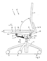
- FIG. 1 is a chair 1 in a first position SI shown in side view partially cut, with a hatching cut surfaces was omitted for the sake of clarity.
- the seating 1 essentially comprises a seat element 2, a back element 3, a support frame 4 and a bogie 5.
- the bogie 5 comprises rollers 6 and a vertical gas spring 7, on which the support frame 4 is fixed.
- the support frame 4 consists essentially of a carrier 8, a Leaf spring element 9 and a mechanical means 10 for transmitting a movement, which is designed as a lever 11.
- the seat element 2 is connected in a front seat 12 via the leaf spring element 9 and in a rear seat 13 via the lever 11 to the carrier 8. With an extension 14, the lever 11 is further designed as a back element support 15, on which the back element 3 is attached.
- the seat element 2 and the back element 3 have in the position SI an opening angle ⁇ of about 80 °.
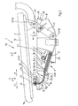
- the FIG. 2 show the FIG. 1 in the region of the support frame 4 in an enlarged view.
- the leaf spring element 9 consists of eight individual leaf springs 9a to 9h with partially different lengths. Furthermore, the leaf spring element 9 has a first, right section A and a second, left section B on. In the first section A, the leaf spring element 9 is clamped between a support surface 8 formed on the support surface 17 and a toothed slide 18 and thus fixed to the support 8.
- the toothed slide 18 is arranged by rotation of this driving and fixed to the support 8 Gear 21 in the direction of arrow v or v 'movable.
- a hardness of the leaf spring element 9 is adjustable.
- the leaf spring element 9 extends approximately bent by 90 °.
- the leaf spring element 9 is fastened to a free end 22 with a sleeve 23 rotatably mounted on the seat element 2 about a rotation axis D23 with a screw 24.
- a support 25 is disposed on the carrier 8. This is formed by a cam 26, which is fastened to the carrier 8 rotatably about a rotation axis D26.
- the leaf spring element 9 can be raised and allows an adjustment of the inclination of the seat member 2.
- the toothed slider 18 and the gear 21 form an upper abutment 27 to this support 25.
- the cam 26 is shown, for example, in a position in which it raises the leaf spring element 9.
- the lever 11 connects the carrier 8 with the rear seat portion 13 of the seat member 2.
- the lever 11 is fixed to the carrier 8 rotatably about a rotation axis D118.
- the seat member 2 is rotatably attached to the lever 11 about a rotation axis D112.
- a latching mechanism 28 is provided between the carrier 8 and the lever 11, through which a rotation of the lever 11 about the rotational axis D118 can be blocked.
- the lever 11 in the in the FIG. 1 and the FIG. 2 shown position 29 is fixed by the latching mechanism 28 to the support 8, causes a load of the seat member 2 with a weight G sitting on the chair 1, not shown a drop in the seat element 2 with its front seat area 12 in an arrow y 'against the leaf spring element 9.
- the seat element 2 rotates about its axis of rotation D112 to the left.
- the leaf spring element 9 causes a counterforce against the rotational force caused by the weight G until a balance of forces is established.
- the lever 11 in the in the FIG. 1 and the FIG. 2 shown position 29 causes a load of the seat member 2 with the weight G of sitting on the chair 1, not shown a movement of the seat element 2.
- the movement is dependent on how the resulting weight in the front or rear seating area 12 or 13 acts on the seat element 2.
- the resulting weight acts on the seat element 2 in the direction of arrow x 'in front of the axis of rotation D23, essentially the above-described rotational movement of the seat element 2 is established about the axis of rotation D112, since the lever 11 can only turn to the right about the rotary bearing D118, because a turn to the left is by one only in the FIG. 2 shown stop 30 is blocked on the support 8.
- the seat element 2 with its rear seating area 13 drops in the direction of the arrow y '.
- the seat member 2 moves with the rotation axis D112 in a clockwise direction on a circular path 31 about the rotation axis D118.
- the leaf spring element 9 fastened to the shaft 23 of the seat element 2 is pulled approximately in an arrow direction x.
- This tensile load causes a movement of the seat member 2 with its axis of rotation D23, for example, on an arcuate path of movement 32, the slope decreases continuously.
- the seat element 2 follows this movement path 32 until a balance of forces is established again.
- FIG. 3 shows a bottom view of the in FIG. 1 shown seat furniture 1 from an arrow III.
- a first rotary handle 33 can be seen, through which the cam 26, which forms the support 25 for the leaf spring element 9, is rotatable.
- the bottom view shows a second rotary handle 34, with which the gear 21 is rotatable, which the tooth slide 18th drives.
- the lever 11 which is designed as a fork 35 and has two arms 35a and 35b, a latching pin 36 is arranged, which forms the latching mechanism 28 and in the directions of the arrow z or z 'is displaceable.
- the locking pin 36 is shown in a first position 37 and in a second position 38.
- the locking pin 36 engages with a nose 39 in the bore 40, which is formed on the carrier 8. As a result, a rotation of the lever 9 is blocked about the rotation axis D118.
- the locking pin 36 is retracted in the direction of arrow z and stands with its nose 39 outside of the carrier 8 and thus can rotate freely about its axis of rotation D118.
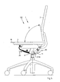
- FIG. 4 is that from the FIGS. 1 to 3 known seating 1 in a second position SII shown in side view.
- the lever 11 is not coupled to the carrier 8 and has as a result of the adjustment of the support 25 about its axis of rotation D118 relative to its in the FIG. 1 shown slightly rotated to the right.
- the opening angle ⁇ between the seat member 2 and the back member 3 is in this position SII as well as in the position SI at about 80 °.
- FIG. 5 which is an enlarged view of FIG. 4 shows in the region of the support frame 4, it can be seen how the cam 26, the leaf spring element 9 deformed in a transition region C and lifts from the support surface 17.
- FIG. 6 is that from the FIGS. 1 to 5 known seating 1 in a third position SIII shown in side view.
- the third position SIII results from the in the FIGS. 4 and 5 shown position SII through the Load of the chair 1 with the weight of a person, not shown, wherein the person not shown also leans against the back member 3.
- the chair 1 reacts by movements of the seat member 2 and the back member 3 in the direction of arrow x, in which case the seat member 2 lifts with its front seat 12 and lowers with its rear seat 13 and wherein the back member 3 also on the Lever 11 rotates about the axis of rotation D118 to the right.
- the opening angle ⁇ between the seat element 2 and the back element 3 also changes.
- the opening angle ⁇ has a value of approximately 95 °.
- FIG. 7 is that from the FIGS. 1 to 6 known seating 1 shown in its two positions SII and SIII in a superimposed representation in the region of the support frame 4.
- the seat element 2 is displaced from a horizontal position into a sloping position to the back element 3 by the deformation of the leaf spring element 9 and the rotation of the lever 11 about the axis of rotation D118 and thereby lifts with its front edge 19 and its lower seating area 13 lowers.
- the rotation axis D23 moves from a point P1 to a point P2
- the rotation axis D112 moves from a point P3 to a point P4.
- the seat member 2 thus moves between a front attachment means 41, which is essentially formed by the leaf spring element 9, and a rear attachment means 42, which is essentially formed by a mechanical means 10 for transmitting a movement, which is designed as a lever 11.
- the back Fastener 42 allows the seat member 2 either the movement on a circular path 31 about the axis of rotation D118 with possibly simultaneous rotation about the axis of rotation D112 or a pure rotation about the axis of rotation D118.
- the front fastening means 41 limits an adjustment of the seat member 2, wherein the position of the rotation axis D23 at which the front fastening element 41 and the seat member 2 are connected to each other can also change and wherein in principle a rotation of the seat member 2 about the rotation axis D23 is possible.
- the position of the back element 3 is determined by the position of the rear fastening element 42, since the back element 3 is articulated thereto.
Landscapes
- Health & Medical Sciences (AREA)
- Dentistry (AREA)
- General Health & Medical Sciences (AREA)
- Chairs For Special Purposes, Such As Reclining Chairs (AREA)
Description
- Die Erfindung betrifft ein Sitzmöbel gemäß dem Oberbegriff des Anspruchs 1.
- Aus der
DE 101 06 792 A1 bzw. derEP 1 230 876 A1 ist ein Sitzmöbel mit einem Sitzelement, einem Rückenelement und einem Traggestell bekannt, wobei das Traggestell einen Träger und ein mechanisches Mittel zur Übertragung einer Bewegung wie Hebel und/oder Führung umfasst, welches den Träger in einem hinteren Sitzbereich mit dem Sitzelement verbindet, wobei als vorderes Befestigungsmittel für das Sitzelement ein Blattfederelement vorgesehen ist, welches an dem feststehenden Träger gelagert ist, wobei das Blattfederelement einen an dem Träger geführten ersten Abschnitt und einen frei zwischen dem Träger und dem Sitzelement liegenden zweiten Abschnitt aufweist. Das Zurücklehnen einer Person auf diesem Sitzmöbel führt zu einem starken Anheben des vorderen Abschnitts des Sitzelements. - Aus der
US 2003/0052520 A1 ist ein ähnliches Sitzmöbel bekannt, bei welchem eine Sitzplatte und ein Sitzplattenträger über Federmittel verbunden sind. - Aus der
JP 08 089359 A - Der Erfindung liegt die Aufgabe zugrunde, mit einfachen Mitteln weitere Verstellmöglichkeiten zu realisieren.
- Diese Aufgabe wird ausgehend von den Merkmalen des Oberbegriffs des Anspruchs 1 durch die kennzeichnenden Merkmale des Anspruchs 1 gelöst. In den Unteransprüchen sind vorteilhafte und zweckmäßige Weiterbildungen angegeben.
- Das erfindungsgemäße Sitzmöbel weist ein Blattfederelement auf, welches in einem ersten Abschnitt schräg nach oben in Richtung einer Vorderkante des Sitzelements weist. Diese Ausrichtung des Blattfederelements führt zu einer Bewegungscharakteristik des Sitzelements, bei welcher sich dieses beim Zurücklehnen einer Person in dem Sitzmöbel in einem vorderen Abschnitt leicht anhebt und auch etwa horizontal in Richtung des Rückenelements verlagert. Somit ist es möglich, allein durch eine erfindungsgemäße Schrägstellung des Blattfederelements die Bewegungscharakteristik des Sitzelements in einer gewünschten Weise zu verändern und somit die Hebebewegung, welche das Sitzelement beim Zurücklehnen einer Person in dem Sitzmöbel ausführt, auf eine gewünschte Größe zu begrenzen. Durch die Schrägstellung des Blattfederelements erlaubt dieses auch eine etwa horizontale Bewegung des Sitzelements.
- Erfindungsgemäß ist es vorgesehen, eine Steigung des Blattfederelements in einem Übergangsbereich, welcher zwischen dem ersten und dem zweiten Abschnitt liegt, durch ein unteres Auflager zu verstellen. Hierdurch ist eine Feinjustierung der Grundstellung des Sitzelements mit einfachen technischen Mitteln möglich.
- Insbesondere ist ein Anheben des Blattfederelements in seinem Übergangsbereich durch das untere Auflager vorgesehen, da hierdurch die in einer Grundeinstellung vorhandene Neigung des Sitzelements zu seiner Vorderkante aufgehoben werden kann.
- Weiterhin ist es vorgesehen, das Auflager als Nocke auszubilden, welche um eine Drehachse zentrisch oder exzentrisch drehbar ist. Hierdurch kann mit technisch einfachen Mitteln in unterschiedlicher Weise auf die Voreinstellung Einfluss genommen werden.
- Weiterhin ist es vorgesehen, in dem ersten Abschnitt des Blattfederelements ein oberes Gegenlager anzuordnen, welches von oben auf das Blattfederelement wirkt, sofern das obere Gegenlager entlang des ersten Abschnitts des Blattfederelements verfahrbar ist, ist es möglich die Härte des Blattfederelements stufenlos einzustellen und so das Sitzelement für Personen mit unterschiedlichem Körpergewicht anzupassen.
- Insbesondere ist es vorgesehen, das obere Gegenlager mit einem Zahnschieber und einem Zahnrad auszustatten, wobei das Blattfederelement zwischen einer Auflagefläche des Trägers und dem Zahnschieber eingeklemmt ist und wobei der Zahnschieber durch eine Drehung des Zahnrads parallel zu der Auflagefläche des Trägers in eine Längsrichtung des Blattfederelements bewegbar ist. Hierdurch ist mit technisch einfachen Mitteln eine stufenlose Einstellbarkeit des Blattfederelements realisierbar.
- Weiterhin ist es vorgesehen, durch eine Verlängerung des Hebels, welcher den Träger und das Sitzelement verbindet, einen Rückenelementträger auszubilden, an welchem das Rückenelement befestigt ist. Hierdurch ist eine Bewegungskopplung des Sitzelements mit dem Rückenelement und somit eine Abfederung des Rückenelements über das Blattfederelement möglich.
- Schließlich sieht die Erfindung eine Fixierbarkeit des Hebels in wenigstens zwei Drehstellungen an dem Träger vor. Hierdurch ist es möglich das Sitzelement und das Rückenelement in bevorzugten Stellungen zu arretieren.
- Weitere Einzelheiten der Erfindung werden in der Zeichnung anhand von schematisch dargestellten Ausführungsbeispielen beschrieben.
- Hierbei zeigt:
-
Figur 1 : ein Sitzmöbel in Seitenansicht in einer ersten Stellung; -
Figur 2 : einen vergrößerten Ausschnitt aus derFigur 1 im Bereich des Traggestells; -
Figur 3 : eine Unteransicht des in derFigur 1 gezeigten Sitzmöbels aus einer Pfeilrichtung III; -
Figur 4 : das Sitzmöbel in Seitenansicht in einer zweiten Stellung; -
Figur 5 : einen vergrößerten Ausschnitt aus derFigur 4 im Bereich des Traggestells; -
Figur 6 : das Sitzmöbel in Seitenansicht in einer dritten Stellung und -
Figur 7 : eine überlagerte Darstellung des erfindungsgemäßen Sitzmöbels in dessen Stellungen SII und SIII. - In
Figur 1 ist ein Sitzmöbel 1 in einer ersten Stellung SI in Seitenansicht teilweise aufgeschnitten dargestellt, wobei auf einer Schraffur geschnittener Flächen zur Erhaltung der Übersichtlichkeit verzichtet wurde. Das Sitzmöbel 1 umfasst im wesentlichen ein Sitzelement 2, ein Rückenelement 3, ein Traggestell 4 und ein Drehgestell 5. Das Drehgestell 5 umfasst Rollen 6 und eine vertikal stehende Gasfeder 7, auf welcher das Traggestell 4 befestigt ist. Das Traggestell 4 besteht im wesentlichen aus einem Träger 8, einem Blattfederelement 9 und einem mechanischen Mittel 10 zur Übertragung einer Bewegung, welches als Hebel 11 ausgebildet ist. Das Sitzelement 2 ist in einem vorderen Sitzbereich 12 über das Blattfederelement 9 und in einem hinteren Sitzbereich 13 über den Hebel 11 mit dem Träger 8 verbunden. Mit einem Fortsatz 14 ist der Hebel 11 weiterhin als Rückenelementträger 15 ausgebildet, an welchem das Rückenelement 3 befestigt ist. In der Stellung SI, in welcher das Sitzmöbel 1 unbelastet ist, weist das Sitzelement 2 gegenüber einer Horizontalen 16 eine Neigung von α = 5° auf und neigt sich in eine Pfeilrichtung x' zu einer Vorderkante 19. Das Sitzelement 2 und das Rückenelement 3 weisen in der Stellung SI einen Öffnungswinkel β von etwa 80° auf. - Die
Figur 2 zeigt dieFigur 1 im Bereich des Traggestells 4 in vergrößerter Darstellung. Das Blattfederelement 9 besteht aus acht einzelnen Blattfedern 9a bis 9h mit teilweise unterschiedlicher Länge. Weiterhin weist das Blattfederelement 9 einen ersten, rechten Abschnitt A und einen zweiten, linken Abschnitt B auf. In dem ersten Abschnitt A ist das Blattfederelement 9 zwischen einer am Träger 8 ausgebildeten Auflagefläche 17 und einem Zahnschieber 18 eingeklemmt und somit an dem Träger 8 befestigt. Der Abschnitt A des Blattfederelements 8 weist schräg nach oben in Richtung der Vorderkante 19 des Sitzelements 2 und steht hierbei in einem Winkel y = 18° zu einer weiteren Horizontalen 20. Der Zahnschieber 18 ist durch Drehung eines diesen antreibenden und ortsfest an dem Träger 8 angeordneten Zahnrads 21 in Pfeilrichtung v bzw. v' verfahrbar. Hierdurch ist eine Härte des Blattfederelements 9 einstellbar. In dem zweiten, linken Abschnitt B verläuft das Blattfederelement 9 etwa um 90° gebogen. Das Blattfederelement 9 ist an einem freien Ende 22 mit einer an dem Sitzelement 2 um eine Drehachse D23 drehbar gelagerten Hülse 23 mit einer Schraube 24 befestigt. In einem Übergangsbereich C des Blattfederelements 9, welcher zwischen den beiden Abschnitten A und B liegt, ist an dem Träger 8 ein Auflager 25 angeordnet. Dieses wird durch eine Nocke 26 gebildet, welche um eine Drehachse D26 drehbar a dem Träger 8 befestigt ist. Durch dieses Auflager 25 ist das Blattfederelement 9 anhebbar und erlaubt eine Verstellung der Neigung des Sitzelements 2. Der Zahnschieber 18 und das Zahnrad 21 bilden ein oberes Gegenlager 27 zu diesem Auflager 25. In derFigur 4 bzw. 5 ist die Nocke 26 beispielweise in einer Stellung gezeigt, in welcher diese das Blattfederelement 9 anhebt. Der Hebel 11 verbindet den Träger 8 mit dem hinteren Sitzbereich 13 des Sitzelements 2. Der Hebel 11 ist an dem Träger 8 drehbar um eine Drehachse D118 befestigt. Das Sitzelement 2 ist an dem Hebel 11 drehbar um eine Drehachse D112 befestigt. Weiterhin ist zwischen dem Träger 8 und dem Hebel 11 ein Rastmechanismus 28 vorgesehen, durch welchen eine Drehbarkeit des Hebels 11 um die Drehachse D118 blockierbar ist. - Sofern der Hebel 11 in der in der
Figur 1 und derFigur 2 gezeigten Stellung 29 durch den Rastmechanismus 28 an dem Träger 8 fixiert ist, bewirkt eine Belastung des Sitzelements 2 mit einer Gewichtskraft G einer auf dem Sitzmöbel 1 sitzenden, nicht dargestellten Person ein Absinken des Sitzelements 2 mit seinem vorderen Sitzbereich 12 in eine Pfeilrichtung y' gegen das Blattfederelement 9. Hierbei dreht sich das Sitzelement 2 um seine Drehachse D112 nach links. Das Blattfederelement 9 bewirkt eine Gegenkraft gegen die durch die Gewichtskraft G bewirkte Drehbewegung bis ein Kräftegleichgewicht hergestellt ist. - Mittels des Rastmechanismus 28, welcher in eine der dargestellten Bohrungen 40 einrasten kann, können unterschiedliche Positionen des Sitzelements 2 bzw. des Rückenelements 3 vorgewählt und fixiert werden.
- Sofern der Hebel 11 in der in der
Figur 1 und derFigur 2 gezeigten Stellung 29 nicht an dem Träger 8 fixiert ist, bewirkt eine Belastung des Sitzelements 2 mit der Gewichtskraft G der auf dem Sitzmöbel 1 sitzenden, nicht dargestellten Person eine Bewegung des Sitzelements 2. Hierbei ist die Bewegung davon abhängig, wie die resultierende Gewichtskraft in dem vorderen oder hinteren Sitzbereich 12 bzw. 13 auf das Sitzelement 2 wirkt. Sofern die resultierende Gewichtskraft in Pfeilrichtung x' vor der Drehachse D23 auf das Sitzelement 2 wirkt, stellt sich im wesentlichen die oben beschriebene Drehbewegung des Sitzelements 2 um die Drehachse D112 ein, da sich der Hebel 11 nur nach rechts um das Drehlager D118 drehen kann, weil eine Drehung nach links ist durch einen nur in derFigur 2 dargestellten Anschlag 30 an dem Träger 8 blockiert. Sofern die Resultierende der Gewichtskraft G zum Beispiel in dem hinteren Sitzbereich 13 des Sitzelements 2 angreift, sinkt das Sitzelement 2 mit seinem hinteren Sitzbereich 13 in die Pfeilrichtung y' ab. Hierbei bewegt sich das Sitzelement 2 mit der Drehachse D112 im Uhrzeigersinn auf einer Kreisbahn 31 um die Drehachse D118. Durch diese Drehbewegung wird das an der Welle 23 des Sitzelements 2 befestigte Blattfederelement 9 etwa in eine Pfeilrichtung x gezogen. Diese Zugbelastung bewirkt eine Bewegung des Sitzelements 2 mit seiner Drehachse D23 beispielsweise auf einer bogenförmigen Bewegungsbahn 32, deren Steigung kontinuierlich abnimmt. Das Sitzelement 2 folgt dieser Bewegungsbahn 32 bis sich wieder ein Kräftegleichgewicht einstellt. - Die
Figur 3 zeigt eine Unteransicht des in derFigur 1 gezeigten Sitzmöbels 1 aus einer Pfeilrichtung III. In der Unteransicht ist ein erster Drehgriff 33 erkennbar, durch welchen die Nocke 26, welche das Auflager 25 für das Blattfederelement 9 bildet, verdrehbar ist. Weiterhin zeigt die Unteransicht einen zweiten Drehgriff 34, mit welchem das Zahnrad 21 verdrehbar ist, welches den Zahnschieber 18 antreibt. An dem Hebel 11, welcher als Gabel 35 ausgebildet ist und zwei Arme 35a und 35b aufweist ist ein Raststift 36 angeordnet, welcher den Rastmechanismus 28 bildet und in Pfeilrichtungen z bzw. z' verschiebbar ist. Der Raststift 36 ist in einer ersten Stellung 37 und in einer zweiten Stellung 38 dargestellt. In der zweiten Stellung 38 greift der Raststift 36 mit einer Nase 39 in die Bohrung 40 ein, welche an dem Träger 8 ausgebildet ist. Hierdurch ist eine Drehbarkeit des Hebels 9 um die Drehachse D118 blockiert. In der erste Stellung 37 ist der Raststift 36 in die Pfeilrichtung z zurückgezogen und steht mit seiner Nase 39 außerhalb des Trägers 8 und kann sich somit frei um seine Drehachse D118 drehen. - In
Figur 4 ist das aus denFiguren 1 bis 3 bekannte Sitzmöbel 1 in einer zweiten Stellung SII in Seitenansicht dargestellt. Durch eine Drehung der Nocke 26 um etwa 90° im Uhrzeigersinn ist das Sitzelement 2 nun gegenüber der in derFigur 1 gezeigten Stellung SI bis in die Horizontale 16 auf einen Neigungswinkel α = 0° angehoben. Der Hebel 11 ist nicht mit dem Träger 8 gekoppelt und hat sich in Folge der Verstellung des Auflagers 25 um seine Drehachse D118 gegenüber seiner in derFigur 1 gezeigten Stellung leicht nach rechts gedreht. Der Öffnungswinkel β zwischen dem Sitzelement 2 und dem Rückenelement 3 liegt in dieser Stellung SII genauso wie in der Stellung SI bei etwa 80°. - In der
Figur 5 , welche eine vergrößerte Darstellung derFigur 4 im Bereich des Traggestells 4 zeigt, ist erkennbar, wie die Nocke 26 das Blattfederelement 9 in einem Übergangsbereich C verformt und von der Auflagefläche 17 abhebt. - In der
Figur 6 ist das aus denFiguren 1 bis 5 bekannte Sitzmöbel 1 in einer dritten Stellung SIII in Seitenansicht dargestellt. Die dritte Stellung SIII ergibt sich aus der in denFiguren 4 und5 gezeigten Stellung SII durch die Belastung des Sitzmöbels 1 mit der Gewichtskraft einer nicht dargestellten Person, wobei sich die nicht dargestellte Person auch gegen das Rückenelement 3 lehnt. Auf die beschriebene Belastung reagiert das Sitzmöbel 1 durch Bewegungen des Sitzelements 2 und des Rückenelements 3 in die Pfeilrichtung x, wobei sich hierbei das Sitzelement 2 mit seinem vorderen Sitzbereich 12 anhebt und mit seinem hinteren Sitzbereich 13 absenkt und wobei sich das Rückenelement 3 auch an dem Hebel 11 um die Drehachse D118 nach rechts dreht. Somit verändert sich neben der Ausrichtung des Sitzelements 2 und des Rückenelements 3 auch der Öffnungswinkel β zwischen dem Sitzelement 2 und dem Rückenelement 3. In der Stellung SIII des Sitzmöbels 1 weist der Öffnungswinkel β einen Wert von etwa 95° auf. - In der
Figur 7 ist das aus denFiguren 1 bis 6 bekannte Sitzmöbel 1 in seinen beiden Stellungen SII und SIII in einer überlagerten Darstellung im Bereich des Traggestells 4 gezeigt. In der überlagerten Darstellung ist erkennbar wie durch die Verformung des Blattfederelements 9 und die Drehung des Hebels 11 um die Drehachse D118 das Sitzelement 2 aus einer waagrechten Stellung in eine zu dem Rückenelement 3 abfallende Stellung verschoben wird und sich hierbei mit seiner Vorderkante 19 anhebt und seinem hinteren Sitzbereich 13 absenkt. Hierzu bewegt sich die Drehachse D23 von einem Punkt P1 zu einem Punkt P2 und die Drehachse D112 von einem Punkt P3 zu einem Punkt P4. Selbstverständlich ist der Hebel 11 bei diesem Bewegungsvorgang, welcher durch die Gewichtskraft der auf dem Sitzmöbel 1 sitzenden, nicht dargestellten Person hervorgerufen wird, nicht an dem Träger 8 arretiert. Das Sitzelement 2 bewegt sich also zwischen einem vorderen Befestigungsmittel 41, welches im wesentlichen durch das Blattfederelement 9 gebildet wird, und einem hinteren Befestigungsmittel 42, welches im wesentlichen durch ein mechanisches Mittel 10 zur Übertragung einer Bewegung gebildet wird, das als Hebel 11 ausgeführt ist. Das hintere Befestigungsmittel 42 erlaubt dem Sitzelement 2 entweder die Bewegung auf einer Kreisbahn 31 um die Drehachse D118 bei ggf. gleichzeitiger Drehung um die Drehachse D112 oder eine reine Drehung um die Drehachse D118. Das vordere Befestigungsmittel 41 begrenzt eine Verstellung des Sitzelements 2, wobei sich die Position der Drehachse D23 an welcher das vordere Befestigungselement 41 und das Sitzelement 2 miteinander verbunden sind ebenfalls verändern kann und wobei grundsätzlich eine Drehung des Sitzelements 2 um die Drehachse D23 möglich ist. Die Stellung des Rückenelements 3 wird durch die Stellung des hinteren Befestigungselements 42 bestimmt, da das Rückenelement 3 an diesem angelenkt ist. - Die Erfindung ist nicht auf dargestellte oder beschriebene Ausführungsbeispiele beschränkt. Sie umfasst vielmehr Weiterbildungen der Erfindung im Rahmen der Schutzrechtsansprüche.
Bezugszeichenliste: 1 Sitzmöbel 2 Sitzelement 3 Rückenelement 3 Traggestell 5 Drehgestell 6 Rolle 7 Gasfeder 8 Träger 9 Blattfederelement 10 mechanisches Mittel zur Übertragung einer Bewegung 11 Hebel 12 vorderer Sitzbereich von 2 13 hinterer Sitzbereich von 2 14 Fortsatz von 11 15 Rückenelementträger 16 erste Horizontale 17 Auflagefläche an 8 18 Zahnschieber 19 Vorderkante von 2 20 zweite Horizontale 21 Zahnrad 22 freies Ende von 9 23 Hülse 24 Schraube zur Befestigung von 9 an 23 25 unteres Auflager 26 Nocke 27 unteres Gegenlager 28 Rastmechanismus 29 Stellung von 11 30 Anschlag an 8 für 11 31 Kreisbahn 32 Bewegungsbahn von D23 33 erster Drehgriff für 26 34 zweiter Drehgriff für 21 35 Gabel 35a, 35b Arm von 35 36 Raststift 37 erste Stellung von 36 38 zweite Stellung von 36 39 Nase von 36 40 Bohrung in 8 41 vorderes Befestigungsmittel 42 hinteres Befestigungsmittel A erster Abschnitt von 9 B zweiter Abschnitt von 9 C Übergangsbereich von 9 zwischen A und B D23 Drehachse von 23 D26 Drehachse von 26 D112 Drehachse zwischen 11 und 2 D118 Drehachse zwischen 11 und 8 G . Gewichtskraft SI erste Stellung von 1 SII zweite Stellung von 1 SIII dritte Stellung von 1 x, x' Raumrichtung y, y' Raumrichtung z, z' Raumrichtung v, v' Raumrichtung w Drehrichtung α Neigung von 2 β Winkel zwischen 2 und 3 γ Neigung von 9 im Abschnitt A
Claims (10)
- Sitzmöbel (1) mit einem Sitzelement (2), einem Rückenelement (3) und einem Traggestell (4), wobei das Traggestell (4) einen Träger (8) und ein mechanisches Mittel (10) zur Übertragung einer Bewegung wie Hebel (11) und/oder Führung umfasst, welches den Träger (8) in einem hinteren Sitzbereich (13) mit dem Sitzelement (2) verbindet, wobei als vorderes Befestigungsmittel (41) für das Sitzelement (2) ein Blattfederelement (9) vorgesehen ist, welches an dem feststehenden Träger (8) gelagert ist, wobei das Blattfederelement (9) einen an dem Träger (8) geführten ersten Abschnitt (A) und einen frei zwischen dem Träger (8) und dem Sitzelement (2) liegenden zweiten Abschnitt (B) aufweist, wobei das Blattfederelement (9) in dem ersten Abschnitt (A) schräg nach oben in Richtung einer Vorderkante (19) des Sitzelements (2) weist, dadurch gekennzeichnet, dass eine Steigung des Blattfederelements (9) in einem Übergangsbereich (C) zwischen dem ersten Abschnitt (A) und dem zweiten Abschnitt (B) durch ein unteres Auflager (25) verstellbar ist.
- Sitzmöbel nach Anspruch 1, dadurch gekennzeichnet, dass das Blattfederelement (9) in seinem Übergangsbereich (C) durch das untere Auflager (25) anhebbar ist.
- Sitzmöbel nach einem der vorhergehenden Ansprüche, dadurch gekennzeichnet, dass untere Auflager (25) als Nocke (26) ausgebildet ist, welche um eine Drehachse (D26) drehbar ist.
- Sitzmöbel nach Anspruch 3, dadurch gekennzeichnet, dass die Nocke (26) zentrisch um die Drehachse (D26) drehbar ist.
- Sitzmöbel nach Anspruch 3, dadurch gekennzeichnet, dass die Nocke (26) exzentrisch um die Drehachse (D26) drehbar ist.
- Sitzmöbel nach einem der vorhergehenden Ansprüche, dadurch gekennzeichnet, dass in dem ersten Abschnitt (A) des Blattfederelements (9) ein oberes Gegenlager (27) angeordnet ist, welches von oben auf das Blattfederelement (9) wirkt.
- Sitzmöbel nach Anspruch 6, dadurch gekennzeichnet, dass das obere Gegenlager (27) entlang des ersten Abschnitts (A) des Blattfederelements (9) verfahrbar ist.
- Sitzmöbel nach wenigstens einem der Ansprüche 6 oder 7, dadurch gekennzeichnet, dass das obere Gegenlager (27) einen Zahnschieber (18) und ein Zahnrad (21) umfasst, wobei das Blattfederelement (9) zwischen einer Auflagefläche (17) des Trägers (8) und dem Zahnschieber (18) eingeklemmt ist und wobei der Zahnschieber (18) durch eine Drehung des Zahnrads (21) parallel zu der Auflagefläche (17) des Trägers (8) in eine Längsrichtung (v, v') des Blattfederelements (9) bewegbar ist.
- Sitzmöbel nach einem der vorhergehenden Ansprüche, dadurch gekennzeichnet, dass eine Verlängerung des Hebels (11) einen Rückenelementträger (15) bildet, an welchem das Rückenelement (3) befestigt ist.
- Sitzmöbel nach einem der vorhergehenden Ansprüche, dadurch gekennzeichnet, dass der Hebel (11) in wenigstens zwei Drehstellungen an dem Träger (8) fixierbar ist.
Priority Applications (1)
| Application Number | Priority Date | Filing Date | Title |
|---|---|---|---|
| EP06776919.0A EP2046165B1 (de) | 2006-06-30 | 2006-08-16 | Sitzmöbel |
Applications Claiming Priority (3)
| Application Number | Priority Date | Filing Date | Title |
|---|---|---|---|
| EP2006006354 | 2006-06-30 | ||
| EP06776919.0A EP2046165B1 (de) | 2006-06-30 | 2006-08-16 | Sitzmöbel |
| PCT/EP2006/008115 WO2008000295A1 (de) | 2006-06-30 | 2006-08-16 | Sitzmöbel |
Publications (2)
| Publication Number | Publication Date |
|---|---|
| EP2046165A1 EP2046165A1 (de) | 2009-04-15 |
| EP2046165B1 true EP2046165B1 (de) | 2013-07-17 |
Family
ID=37836785
Family Applications (1)
| Application Number | Title | Priority Date | Filing Date |
|---|---|---|---|
| EP06776919.0A Not-in-force EP2046165B1 (de) | 2006-06-30 | 2006-08-16 | Sitzmöbel |
Country Status (2)
| Country | Link |
|---|---|
| EP (1) | EP2046165B1 (de) |
| WO (1) | WO2008000295A1 (de) |
Families Citing this family (16)
| Publication number | Priority date | Publication date | Assignee | Title |
|---|---|---|---|---|
| CH708248A1 (de) | 2013-06-28 | 2014-12-31 | Sitag Ag | Sitzmöbel mit Biegefeder. |
| US10194750B2 (en) | 2015-04-13 | 2019-02-05 | Steelcase Inc. | Seating arrangement |
| US11259637B2 (en) | 2015-04-13 | 2022-03-01 | Steelcase Inc. | Seating arrangement |
| EP3984413A1 (de) | 2015-04-13 | 2022-04-20 | Steelcase Inc. | Sitzanordnung |
| US10966527B2 (en) | 2017-06-09 | 2021-04-06 | Steelcase Inc. | Seating arrangement and method of construction |
| DE102017209041A1 (de) * | 2017-05-30 | 2018-12-06 | Sedus Stoll Ag | Stuhl, insbesondere Konferenz- oder Bürostuhl sowie Verfahren zur Herstellung eines Stuhls |
| US10820703B2 (en) | 2018-09-17 | 2020-11-03 | Sedus Stoll Ag | Chair, particularly conference or office chair, and method for manufacturing a chair |
| DE102018219885B4 (de) * | 2018-11-20 | 2022-02-03 | Comfordy Co., Ltd. | Synchronmechanik für ein Sitzmöbel und Sitzmöbel |
| EP4268676A3 (de) | 2019-02-21 | 2024-02-07 | Steelcase Inc. | Körperstützanordnung und verfahren zur verwendung und montage davon |
| US11357329B2 (en) | 2019-12-13 | 2022-06-14 | Steelcase Inc. | Body support assembly and methods for the use and assembly thereof |
| IT202000002332A1 (it) * | 2020-02-06 | 2021-08-06 | Donati Spa | Meccanismo di oscillazione per una sedia o una poltroncina |
| WO2021178206A1 (en) | 2020-03-02 | 2021-09-10 | Steelcase Inc. | Body support assembly and methods for the use and assembly thereof |
| CN112757985B (zh) * | 2021-02-04 | 2022-02-22 | 麦格纳座椅研发(重庆)有限公司 | 带无级调节的座椅桌板 |
| WO2022173799A1 (en) | 2021-02-10 | 2022-08-18 | Steelcase Inc. | Body support structure |
| IT202200009566A1 (it) | 2022-05-10 | 2023-11-10 | Brado S P A | Dispositivo di regolazione per una sedia con meccanismo oscillante |
| DE102023111819A1 (de) * | 2023-05-05 | 2024-11-07 | Bock 1 Gmbh & Co. Kg | Mechanik für ein Sitzmöbel, insbesondere für einen Bürostuhl |
Family Cites Families (5)
| Publication number | Priority date | Publication date | Assignee | Title |
|---|---|---|---|---|
| JPH03222907A (ja) * | 1989-11-30 | 1991-10-01 | Itoki Kosakusho Co Ltd | 椅子の弾力調節装置 |
| JP2919131B2 (ja) * | 1991-10-22 | 1999-07-12 | 株式会社イトーキクレビオ | 椅子の傾動制御装置 |
| JPH0889359A (ja) | 1994-09-22 | 1996-04-09 | Inoue Assoc:Kk | 椅子の座板と背もたれの揺動機構 |
| WO2001070074A1 (de) | 2000-03-24 | 2001-09-27 | Giroflex-Entwicklungs-Ag | Sitz- und rückenlehnen-anordnung bei sitzmöbeln, insbesondere bürostühlen |
| DE10106792A1 (de) | 2001-02-12 | 2002-08-14 | Interstuhl Bueromoebel Gmbh | Sitzmöbel |
-
2006
- 2006-08-16 EP EP06776919.0A patent/EP2046165B1/de not_active Not-in-force
- 2006-08-16 WO PCT/EP2006/008115 patent/WO2008000295A1/de not_active Ceased
Also Published As
| Publication number | Publication date |
|---|---|
| WO2008000295A1 (de) | 2008-01-03 |
| EP2046165A1 (de) | 2009-04-15 |
Similar Documents
| Publication | Publication Date | Title |
|---|---|---|
| EP0960586B1 (de) | Stuhl, insbesondere Bürostuhl | |
| EP2046165A1 (de) | Sitzmöbel | |
| EP3996553B1 (de) | Klappsitz für ein schienenfahrzeug | |
| EP3423301B1 (de) | Kopfstütze mit verbesserter verstelleinrichtung | |
| EP0198056B1 (de) | Sitzträger für stühle, insbesondere arbeitsdrehstühle | |
| EP1358821A1 (de) | Stuhl mit vom Benutzergewicht abhängigen Kraftspeicher | |
| DE2232117B2 (de) | Höhen- und neigungsverstellbarer Fahrzeugsitz | |
| EP1258211B1 (de) | Synchronmechanik für die simultane Sitzflächen- und Rückenlehnen-Schwenkbewegung bei Bürostühlen | |
| DE102015111946A1 (de) | Mechanik für einen Bürostuhl | |
| EP1989961B1 (de) | Synchronmechanik für Bürostühle | |
| DE102005029906B3 (de) | Synchronmechanik | |
| EP1874162A1 (de) | Synchronmechanik | |
| BE1017878A5 (de) | Sitzmoebel. | |
| EP1683441B1 (de) | Synchronmechanik | |
| EP1874160A1 (de) | Sitzmöbel, insbesondere bürostuhl | |
| DE69714910T2 (de) | Verstellvorrichtung | |
| DE3724582C2 (de) | ||
| EP0341344A2 (de) | Sitzmöbel | |
| DE19527750C2 (de) | Fahrzeugsitz | |
| WO2002091880A1 (de) | Bürostuhl | |
| DE10147548C1 (de) | Federmechanik zur Gewichtseinstellung für einen Stuhl | |
| EP2177132A1 (de) | Vorrichtung zur Sitzneigungsverstellung und Stuhl | |
| EP4458215B1 (de) | Mechanik für ein sitzmöbel, insbesondere für einen bürostuhl | |
| DE102006021472B4 (de) | Pedalanordnung mit einem hängenden Pedal | |
| DE29723702U1 (de) | Stuhl, insbesondere Bürostuhl |
Legal Events
| Date | Code | Title | Description |
|---|---|---|---|
| PUAI | Public reference made under article 153(3) epc to a published international application that has entered the european phase |
Free format text: ORIGINAL CODE: 0009012 |
|
| 17P | Request for examination filed |
Effective date: 20081204 |
|
| AK | Designated contracting states |
Kind code of ref document: A1 Designated state(s): AT BE BG CH CY CZ DE DK EE ES FI FR GB GR HU IE IS IT LI LT LU LV MC NL PL PT RO SE SI SK TR |
|
| AX | Request for extension of the european patent |
Extension state: AL BA HR MK RS |
|
| 17Q | First examination report despatched |
Effective date: 20091012 |
|
| DAX | Request for extension of the european patent (deleted) | ||
| GRAP | Despatch of communication of intention to grant a patent |
Free format text: ORIGINAL CODE: EPIDOSNIGR1 |
|
| GRAS | Grant fee paid |
Free format text: ORIGINAL CODE: EPIDOSNIGR3 |
|
| GRAA | (expected) grant |
Free format text: ORIGINAL CODE: 0009210 |
|
| AK | Designated contracting states |
Kind code of ref document: B1 Designated state(s): AT BE BG CH CY CZ DE DK EE ES FI FR GB GR HU IE IS IT LI LT LU LV MC NL PL PT RO SE SI SK TR |
|
| REG | Reference to a national code |
Ref country code: GB Ref legal event code: FG4D Free format text: NOT ENGLISH |
|
| REG | Reference to a national code |
Ref country code: CH Ref legal event code: EP |
|
| REG | Reference to a national code |
Ref country code: IE Ref legal event code: FG4D Free format text: LANGUAGE OF EP DOCUMENT: GERMAN |
|
| REG | Reference to a national code |
Ref country code: AT Ref legal event code: REF Ref document number: 621637 Country of ref document: AT Kind code of ref document: T Effective date: 20130815 |
|
| REG | Reference to a national code |
Ref country code: DE Ref legal event code: R096 Ref document number: 502006013041 Country of ref document: DE Effective date: 20130912 |
|
| REG | Reference to a national code |
Ref country code: NL Ref legal event code: VDEP Effective date: 20130717 |
|
| REG | Reference to a national code |
Ref country code: LT Ref legal event code: MG4D |
|
| PG25 | Lapsed in a contracting state [announced via postgrant information from national office to epo] |
Ref country code: LT Free format text: LAPSE BECAUSE OF FAILURE TO SUBMIT A TRANSLATION OF THE DESCRIPTION OR TO PAY THE FEE WITHIN THE PRESCRIBED TIME-LIMIT Effective date: 20130717 Ref country code: CY Free format text: LAPSE BECAUSE OF FAILURE TO SUBMIT A TRANSLATION OF THE DESCRIPTION OR TO PAY THE FEE WITHIN THE PRESCRIBED TIME-LIMIT Effective date: 20130731 Ref country code: IS Free format text: LAPSE BECAUSE OF FAILURE TO SUBMIT A TRANSLATION OF THE DESCRIPTION OR TO PAY THE FEE WITHIN THE PRESCRIBED TIME-LIMIT Effective date: 20131117 Ref country code: PT Free format text: LAPSE BECAUSE OF FAILURE TO SUBMIT A TRANSLATION OF THE DESCRIPTION OR TO PAY THE FEE WITHIN THE PRESCRIBED TIME-LIMIT Effective date: 20131118 Ref country code: SE Free format text: LAPSE BECAUSE OF FAILURE TO SUBMIT A TRANSLATION OF THE DESCRIPTION OR TO PAY THE FEE WITHIN THE PRESCRIBED TIME-LIMIT Effective date: 20130717 |
|
| BERE | Be: lapsed |
Owner name: HANSEN, ECKHARD, DIPL.-ING. Effective date: 20130831 |
|
| PG25 | Lapsed in a contracting state [announced via postgrant information from national office to epo] |
Ref country code: PL Free format text: LAPSE BECAUSE OF FAILURE TO SUBMIT A TRANSLATION OF THE DESCRIPTION OR TO PAY THE FEE WITHIN THE PRESCRIBED TIME-LIMIT Effective date: 20130717 Ref country code: ES Free format text: LAPSE BECAUSE OF FAILURE TO SUBMIT A TRANSLATION OF THE DESCRIPTION OR TO PAY THE FEE WITHIN THE PRESCRIBED TIME-LIMIT Effective date: 20131028 Ref country code: GR Free format text: LAPSE BECAUSE OF FAILURE TO SUBMIT A TRANSLATION OF THE DESCRIPTION OR TO PAY THE FEE WITHIN THE PRESCRIBED TIME-LIMIT Effective date: 20131018 Ref country code: SI Free format text: LAPSE BECAUSE OF FAILURE TO SUBMIT A TRANSLATION OF THE DESCRIPTION OR TO PAY THE FEE WITHIN THE PRESCRIBED TIME-LIMIT Effective date: 20130717 Ref country code: FI Free format text: LAPSE BECAUSE OF FAILURE TO SUBMIT A TRANSLATION OF THE DESCRIPTION OR TO PAY THE FEE WITHIN THE PRESCRIBED TIME-LIMIT Effective date: 20130717 Ref country code: NL Free format text: LAPSE BECAUSE OF FAILURE TO SUBMIT A TRANSLATION OF THE DESCRIPTION OR TO PAY THE FEE WITHIN THE PRESCRIBED TIME-LIMIT Effective date: 20130717 Ref country code: LV Free format text: LAPSE BECAUSE OF FAILURE TO SUBMIT A TRANSLATION OF THE DESCRIPTION OR TO PAY THE FEE WITHIN THE PRESCRIBED TIME-LIMIT Effective date: 20130717 |
|
| PG25 | Lapsed in a contracting state [announced via postgrant information from national office to epo] |
Ref country code: CY Free format text: LAPSE BECAUSE OF FAILURE TO SUBMIT A TRANSLATION OF THE DESCRIPTION OR TO PAY THE FEE WITHIN THE PRESCRIBED TIME-LIMIT Effective date: 20130717 |
|
| REG | Reference to a national code |
Ref country code: CH Ref legal event code: PL |
|
| PG25 | Lapsed in a contracting state [announced via postgrant information from national office to epo] |
Ref country code: LI Free format text: LAPSE BECAUSE OF NON-PAYMENT OF DUE FEES Effective date: 20130831 Ref country code: MC Free format text: LAPSE BECAUSE OF FAILURE TO SUBMIT A TRANSLATION OF THE DESCRIPTION OR TO PAY THE FEE WITHIN THE PRESCRIBED TIME-LIMIT Effective date: 20130717 Ref country code: DK Free format text: LAPSE BECAUSE OF FAILURE TO SUBMIT A TRANSLATION OF THE DESCRIPTION OR TO PAY THE FEE WITHIN THE PRESCRIBED TIME-LIMIT Effective date: 20130717 Ref country code: CH Free format text: LAPSE BECAUSE OF NON-PAYMENT OF DUE FEES Effective date: 20130831 Ref country code: SK Free format text: LAPSE BECAUSE OF FAILURE TO SUBMIT A TRANSLATION OF THE DESCRIPTION OR TO PAY THE FEE WITHIN THE PRESCRIBED TIME-LIMIT Effective date: 20130717 Ref country code: EE Free format text: LAPSE BECAUSE OF FAILURE TO SUBMIT A TRANSLATION OF THE DESCRIPTION OR TO PAY THE FEE WITHIN THE PRESCRIBED TIME-LIMIT Effective date: 20130717 Ref country code: RO Free format text: LAPSE BECAUSE OF FAILURE TO SUBMIT A TRANSLATION OF THE DESCRIPTION OR TO PAY THE FEE WITHIN THE PRESCRIBED TIME-LIMIT Effective date: 20130717 Ref country code: CZ Free format text: LAPSE BECAUSE OF FAILURE TO SUBMIT A TRANSLATION OF THE DESCRIPTION OR TO PAY THE FEE WITHIN THE PRESCRIBED TIME-LIMIT Effective date: 20130717 |
|
| REG | Reference to a national code |
Ref country code: IE Ref legal event code: MM4A |
|
| PLBE | No opposition filed within time limit |
Free format text: ORIGINAL CODE: 0009261 |
|
| REG | Reference to a national code |
Ref country code: FR Ref legal event code: ST Effective date: 20140430 |
|
| STAA | Information on the status of an ep patent application or granted ep patent |
Free format text: STATUS: NO OPPOSITION FILED WITHIN TIME LIMIT |
|
| PG25 | Lapsed in a contracting state [announced via postgrant information from national office to epo] |
Ref country code: BE Free format text: LAPSE BECAUSE OF NON-PAYMENT OF DUE FEES Effective date: 20130831 Ref country code: IT Free format text: LAPSE BECAUSE OF FAILURE TO SUBMIT A TRANSLATION OF THE DESCRIPTION OR TO PAY THE FEE WITHIN THE PRESCRIBED TIME-LIMIT Effective date: 20130717 |
|
| 26N | No opposition filed |
Effective date: 20140422 |
|
| GBPC | Gb: european patent ceased through non-payment of renewal fee |
Effective date: 20131017 |
|
| PG25 | Lapsed in a contracting state [announced via postgrant information from national office to epo] |
Ref country code: IE Free format text: LAPSE BECAUSE OF NON-PAYMENT OF DUE FEES Effective date: 20130816 Ref country code: GB Free format text: LAPSE BECAUSE OF NON-PAYMENT OF DUE FEES Effective date: 20131017 |
|
| REG | Reference to a national code |
Ref country code: DE Ref legal event code: R097 Ref document number: 502006013041 Country of ref document: DE Effective date: 20140422 |
|
| PG25 | Lapsed in a contracting state [announced via postgrant information from national office to epo] |
Ref country code: FR Free format text: LAPSE BECAUSE OF NON-PAYMENT OF DUE FEES Effective date: 20130917 |
|
| REG | Reference to a national code |
Ref country code: AT Ref legal event code: MM01 Ref document number: 621637 Country of ref document: AT Kind code of ref document: T Effective date: 20130816 |
|
| PG25 | Lapsed in a contracting state [announced via postgrant information from national office to epo] |
Ref country code: AT Free format text: LAPSE BECAUSE OF NON-PAYMENT OF DUE FEES Effective date: 20130816 |
|
| PG25 | Lapsed in a contracting state [announced via postgrant information from national office to epo] |
Ref country code: TR Free format text: LAPSE BECAUSE OF FAILURE TO SUBMIT A TRANSLATION OF THE DESCRIPTION OR TO PAY THE FEE WITHIN THE PRESCRIBED TIME-LIMIT Effective date: 20130717 |
|
| PG25 | Lapsed in a contracting state [announced via postgrant information from national office to epo] |
Ref country code: HU Free format text: LAPSE BECAUSE OF FAILURE TO SUBMIT A TRANSLATION OF THE DESCRIPTION OR TO PAY THE FEE WITHIN THE PRESCRIBED TIME-LIMIT; INVALID AB INITIO Effective date: 20060816 Ref country code: BG Free format text: LAPSE BECAUSE OF FAILURE TO SUBMIT A TRANSLATION OF THE DESCRIPTION OR TO PAY THE FEE WITHIN THE PRESCRIBED TIME-LIMIT Effective date: 20130717 Ref country code: LU Free format text: LAPSE BECAUSE OF NON-PAYMENT OF DUE FEES Effective date: 20130816 |
|
| PGFP | Annual fee paid to national office [announced via postgrant information from national office to epo] |
Ref country code: DE Payment date: 20150921 Year of fee payment: 10 |
|
| REG | Reference to a national code |
Ref country code: DE Ref legal event code: R119 Ref document number: 502006013041 Country of ref document: DE |
|
| PG25 | Lapsed in a contracting state [announced via postgrant information from national office to epo] |
Ref country code: DE Free format text: LAPSE BECAUSE OF NON-PAYMENT OF DUE FEES Effective date: 20170301 |