EP2048338A1 - Verfahren zur ventilsteuerung eines dieselmotors - Google Patents
Verfahren zur ventilsteuerung eines dieselmotors Download PDFInfo
- Publication number
- EP2048338A1 EP2048338A1 EP07744736A EP07744736A EP2048338A1 EP 2048338 A1 EP2048338 A1 EP 2048338A1 EP 07744736 A EP07744736 A EP 07744736A EP 07744736 A EP07744736 A EP 07744736A EP 2048338 A1 EP2048338 A1 EP 2048338A1
- Authority
- EP
- European Patent Office
- Prior art keywords
- timing
- valve
- air intake
- closing
- controlling
- Prior art date
- Legal status (The legal status is an assumption and is not a legal conclusion. Google has not performed a legal analysis and makes no representation as to the accuracy of the status listed.)
- Withdrawn
Links
Images




Classifications
-
- F—MECHANICAL ENGINEERING; LIGHTING; HEATING; WEAPONS; BLASTING
- F02—COMBUSTION ENGINES; HOT-GAS OR COMBUSTION-PRODUCT ENGINE PLANTS
- F02D—CONTROLLING COMBUSTION ENGINES
- F02D13/00—Controlling the engine output power by varying inlet or exhaust valve operating characteristics, e.g. timing
- F02D13/02—Controlling the engine output power by varying inlet or exhaust valve operating characteristics, e.g. timing during engine operation
- F02D13/0223—Variable control of the intake valves only
- F02D13/0234—Variable control of the intake valves only changing the valve timing only
- F02D13/0238—Variable control of the intake valves only changing the valve timing only by shifting the phase, i.e. the opening periods of the valves are constant
-
- F—MECHANICAL ENGINEERING; LIGHTING; HEATING; WEAPONS; BLASTING
- F01—MACHINES OR ENGINES IN GENERAL; ENGINE PLANTS IN GENERAL; STEAM ENGINES
- F01L—CYCLICALLY OPERATING VALVES FOR MACHINES OR ENGINES
- F01L1/00—Valve-gear or valve arrangements, e.g. lift-valve gear
- F01L1/34—Valve-gear or valve arrangements, e.g. lift-valve gear characterised by the provision of means for changing the timing of the valves without changing the duration of opening and without affecting the magnitude of the valve lift
- F01L1/344—Valve-gear or valve arrangements, e.g. lift-valve gear characterised by the provision of means for changing the timing of the valves without changing the duration of opening and without affecting the magnitude of the valve lift changing the angular relationship between crankshaft and camshaft, e.g. using helicoidal gear
- F01L1/3442—Valve-gear or valve arrangements, e.g. lift-valve gear characterised by the provision of means for changing the timing of the valves without changing the duration of opening and without affecting the magnitude of the valve lift changing the angular relationship between crankshaft and camshaft, e.g. using helicoidal gear using hydraulic chambers with variable volume to transmit the rotating force
-
- F—MECHANICAL ENGINEERING; LIGHTING; HEATING; WEAPONS; BLASTING
- F02—COMBUSTION ENGINES; HOT-GAS OR COMBUSTION-PRODUCT ENGINE PLANTS
- F02D—CONTROLLING COMBUSTION ENGINES
- F02D41/00—Electrical control of supply of combustible mixture or its constituents
- F02D41/0002—Controlling intake air
-
- F—MECHANICAL ENGINEERING; LIGHTING; HEATING; WEAPONS; BLASTING
- F02—COMBUSTION ENGINES; HOT-GAS OR COMBUSTION-PRODUCT ENGINE PLANTS
- F02M—SUPPLYING COMBUSTION ENGINES IN GENERAL WITH COMBUSTIBLE MIXTURES OR CONSTITUENTS THEREOF
- F02M61/00—Fuel-injectors not provided for in groups F02M39/00 - F02M57/00 or F02M67/00
- F02M61/16—Details not provided for in, or of interest apart from, the apparatus of groups F02M61/02 - F02M61/14
- F02M61/18—Injection nozzles, e.g. having valve seats; Details of valve member seated ends, not otherwise provided for
- F02M61/1806—Injection nozzles, e.g. having valve seats; Details of valve member seated ends, not otherwise provided for characterised by the arrangement of discharge orifices, e.g. orientation or size
- F02M61/182—Discharge orifices being situated in different transversal planes with respect to valve member direction of movement
-
- F—MECHANICAL ENGINEERING; LIGHTING; HEATING; WEAPONS; BLASTING
- F01—MACHINES OR ENGINES IN GENERAL; ENGINE PLANTS IN GENERAL; STEAM ENGINES
- F01L—CYCLICALLY OPERATING VALVES FOR MACHINES OR ENGINES
- F01L1/00—Valve-gear or valve arrangements, e.g. lift-valve gear
- F01L1/02—Valve drive
- F01L1/04—Valve drive by means of cams, camshafts, cam discs, eccentrics or the like
- F01L1/047—Camshafts
- F01L1/053—Camshafts overhead type
- F01L2001/0537—Double overhead camshafts [DOHC]
-
- F—MECHANICAL ENGINEERING; LIGHTING; HEATING; WEAPONS; BLASTING
- F01—MACHINES OR ENGINES IN GENERAL; ENGINE PLANTS IN GENERAL; STEAM ENGINES
- F01L—CYCLICALLY OPERATING VALVES FOR MACHINES OR ENGINES
- F01L3/00—Lift-valve, i.e. cut-off apparatus with closure members having at least a component of their opening and closing motion perpendicular to the closing faces; Parts or accessories thereof
- F01L2003/25—Valve configurations in relation to engine
- F01L2003/253—Valve configurations in relation to engine configured parallel to piston axis
-
- F—MECHANICAL ENGINEERING; LIGHTING; HEATING; WEAPONS; BLASTING
- F01—MACHINES OR ENGINES IN GENERAL; ENGINE PLANTS IN GENERAL; STEAM ENGINES
- F01L—CYCLICALLY OPERATING VALVES FOR MACHINES OR ENGINES
- F01L2800/00—Methods of operation using a variable valve timing mechanism
- F01L2800/10—Providing exhaust gas recirculation [EGR]
-
- F—MECHANICAL ENGINEERING; LIGHTING; HEATING; WEAPONS; BLASTING
- F02—COMBUSTION ENGINES; HOT-GAS OR COMBUSTION-PRODUCT ENGINE PLANTS
- F02B—INTERNAL-COMBUSTION PISTON ENGINES; COMBUSTION ENGINES IN GENERAL
- F02B2275/00—Other engines, components or details, not provided for in other groups of this subclass
- F02B2275/14—Direct injection into combustion chamber
-
- F—MECHANICAL ENGINEERING; LIGHTING; HEATING; WEAPONS; BLASTING
- F02—COMBUSTION ENGINES; HOT-GAS OR COMBUSTION-PRODUCT ENGINE PLANTS
- F02B—INTERNAL-COMBUSTION PISTON ENGINES; COMBUSTION ENGINES IN GENERAL
- F02B3/00—Engines characterised by air compression and subsequent fuel addition
- F02B3/06—Engines characterised by air compression and subsequent fuel addition with compression ignition
-
- F—MECHANICAL ENGINEERING; LIGHTING; HEATING; WEAPONS; BLASTING
- F02—COMBUSTION ENGINES; HOT-GAS OR COMBUSTION-PRODUCT ENGINE PLANTS
- F02B—INTERNAL-COMBUSTION PISTON ENGINES; COMBUSTION ENGINES IN GENERAL
- F02B31/00—Modifying induction systems for imparting a rotation to the charge in the cylinder
- F02B31/04—Modifying induction systems for imparting a rotation to the charge in the cylinder by means within the induction channel, e.g. deflectors
- F02B31/06—Movable means, e.g. butterfly valves
-
- F—MECHANICAL ENGINEERING; LIGHTING; HEATING; WEAPONS; BLASTING
- F02—COMBUSTION ENGINES; HOT-GAS OR COMBUSTION-PRODUCT ENGINE PLANTS
- F02D—CONTROLLING COMBUSTION ENGINES
- F02D13/00—Controlling the engine output power by varying inlet or exhaust valve operating characteristics, e.g. timing
- F02D13/02—Controlling the engine output power by varying inlet or exhaust valve operating characteristics, e.g. timing during engine operation
- F02D13/0261—Controlling the valve overlap
-
- F—MECHANICAL ENGINEERING; LIGHTING; HEATING; WEAPONS; BLASTING
- F02—COMBUSTION ENGINES; HOT-GAS OR COMBUSTION-PRODUCT ENGINE PLANTS
- F02D—CONTROLLING COMBUSTION ENGINES
- F02D41/00—Electrical control of supply of combustible mixture or its constituents
- F02D41/0002—Controlling intake air
- F02D2041/001—Controlling intake air for engines with variable valve actuation
-
- F—MECHANICAL ENGINEERING; LIGHTING; HEATING; WEAPONS; BLASTING
- F02—COMBUSTION ENGINES; HOT-GAS OR COMBUSTION-PRODUCT ENGINE PLANTS
- F02D—CONTROLLING COMBUSTION ENGINES
- F02D41/00—Electrical control of supply of combustible mixture or its constituents
- F02D41/0002—Controlling intake air
- F02D2041/0015—Controlling intake air for engines with means for controlling swirl or tumble flow, e.g. by using swirl valves
-
- F—MECHANICAL ENGINEERING; LIGHTING; HEATING; WEAPONS; BLASTING
- F02—COMBUSTION ENGINES; HOT-GAS OR COMBUSTION-PRODUCT ENGINE PLANTS
- F02D—CONTROLLING COMBUSTION ENGINES
- F02D2200/00—Input parameters for engine control
- F02D2200/02—Input parameters for engine control the parameters being related to the engine
- F02D2200/04—Engine intake system parameters
- F02D2200/0414—Air temperature
-
- F—MECHANICAL ENGINEERING; LIGHTING; HEATING; WEAPONS; BLASTING
- F02—COMBUSTION ENGINES; HOT-GAS OR COMBUSTION-PRODUCT ENGINE PLANTS
- F02D—CONTROLLING COMBUSTION ENGINES
- F02D2200/00—Input parameters for engine control
- F02D2200/02—Input parameters for engine control the parameters being related to the engine
- F02D2200/06—Fuel or fuel supply system parameters
- F02D2200/0606—Fuel temperature
-
- F—MECHANICAL ENGINEERING; LIGHTING; HEATING; WEAPONS; BLASTING
- F02—COMBUSTION ENGINES; HOT-GAS OR COMBUSTION-PRODUCT ENGINE PLANTS
- F02D—CONTROLLING COMBUSTION ENGINES
- F02D2200/00—Input parameters for engine control
- F02D2200/02—Input parameters for engine control the parameters being related to the engine
- F02D2200/06—Fuel or fuel supply system parameters
- F02D2200/0611—Fuel type, fuel composition or fuel quality
-
- F—MECHANICAL ENGINEERING; LIGHTING; HEATING; WEAPONS; BLASTING
- F02—COMBUSTION ENGINES; HOT-GAS OR COMBUSTION-PRODUCT ENGINE PLANTS
- F02D—CONTROLLING COMBUSTION ENGINES
- F02D41/00—Electrical control of supply of combustible mixture or its constituents
- F02D41/0025—Controlling engines characterised by use of non-liquid fuels, pluralities of fuels, or non-fuel substances added to the combustible mixtures
- F02D41/0047—Controlling exhaust gas recirculation [EGR]
- F02D41/0065—Specific aspects of external EGR control
- F02D41/0072—Estimating, calculating or determining the EGR rate, amount or flow
-
- F—MECHANICAL ENGINEERING; LIGHTING; HEATING; WEAPONS; BLASTING
- F02—COMBUSTION ENGINES; HOT-GAS OR COMBUSTION-PRODUCT ENGINE PLANTS
- F02M—SUPPLYING COMBUSTION ENGINES IN GENERAL WITH COMBUSTIBLE MIXTURES OR CONSTITUENTS THEREOF
- F02M26/00—Engine-pertinent apparatus for adding exhaust gases to combustion-air, main fuel or fuel-air mixture, e.g. by exhaust gas recirculation [EGR] systems
- F02M26/01—Internal exhaust gas recirculation, i.e. wherein the residual exhaust gases are trapped in the cylinder or pushed back from the intake or the exhaust manifold into the combustion chamber without the use of additional passages
-
- F—MECHANICAL ENGINEERING; LIGHTING; HEATING; WEAPONS; BLASTING
- F02—COMBUSTION ENGINES; HOT-GAS OR COMBUSTION-PRODUCT ENGINE PLANTS
- F02M—SUPPLYING COMBUSTION ENGINES IN GENERAL WITH COMBUSTIBLE MIXTURES OR CONSTITUENTS THEREOF
- F02M26/00—Engine-pertinent apparatus for adding exhaust gases to combustion-air, main fuel or fuel-air mixture, e.g. by exhaust gas recirculation [EGR] systems
- F02M26/13—Arrangement or layout of EGR passages, e.g. in relation to specific engine parts or for incorporation of accessories
-
- F—MECHANICAL ENGINEERING; LIGHTING; HEATING; WEAPONS; BLASTING
- F02—COMBUSTION ENGINES; HOT-GAS OR COMBUSTION-PRODUCT ENGINE PLANTS
- F02M—SUPPLYING COMBUSTION ENGINES IN GENERAL WITH COMBUSTIBLE MIXTURES OR CONSTITUENTS THEREOF
- F02M47/00—Fuel-injection apparatus operated cyclically with fuel-injection valves actuated by fluid pressure
- F02M47/02—Fuel-injection apparatus operated cyclically with fuel-injection valves actuated by fluid pressure of accumulator-injector type, i.e. having fuel pressure of accumulator tending to open, and fuel pressure in other chamber tending to close, injection valves and having means for periodically releasing that closing pressure
- F02M47/027—Electrically actuated valves draining the chamber to release the closing pressure
-
- Y—GENERAL TAGGING OF NEW TECHNOLOGICAL DEVELOPMENTS; GENERAL TAGGING OF CROSS-SECTIONAL TECHNOLOGIES SPANNING OVER SEVERAL SECTIONS OF THE IPC; TECHNICAL SUBJECTS COVERED BY FORMER USPC CROSS-REFERENCE ART COLLECTIONS [XRACs] AND DIGESTS
- Y02—TECHNOLOGIES OR APPLICATIONS FOR MITIGATION OR ADAPTATION AGAINST CLIMATE CHANGE
- Y02T—CLIMATE CHANGE MITIGATION TECHNOLOGIES RELATED TO TRANSPORTATION
- Y02T10/00—Road transport of goods or passengers
- Y02T10/10—Internal combustion engine [ICE] based vehicles
- Y02T10/12—Improving ICE efficiencies
-
- Y—GENERAL TAGGING OF NEW TECHNOLOGICAL DEVELOPMENTS; GENERAL TAGGING OF CROSS-SECTIONAL TECHNOLOGIES SPANNING OVER SEVERAL SECTIONS OF THE IPC; TECHNICAL SUBJECTS COVERED BY FORMER USPC CROSS-REFERENCE ART COLLECTIONS [XRACs] AND DIGESTS
- Y02—TECHNOLOGIES OR APPLICATIONS FOR MITIGATION OR ADAPTATION AGAINST CLIMATE CHANGE
- Y02T—CLIMATE CHANGE MITIGATION TECHNOLOGIES RELATED TO TRANSPORTATION
- Y02T10/00—Road transport of goods or passengers
- Y02T10/10—Internal combustion engine [ICE] based vehicles
- Y02T10/40—Engine management systems
Definitions
- the present invention relates to a technique for controlling a valve timing of a diesel engine equipped with a common-rail fuel injection device, more specifically, a technique for controlling a valve timing suitable for a common-rail diesel engine, provided with a fuel injection device including an injector having a plurality of intersections between an axis line of the injector and the axes of injection holes bored in a nozzle body of the injector, or a group of injection holes.
- the injector having a group of injection holes can have smaller injection holes than an injector having the same amount of injection quantity without a group of injection holes. Therefore, it is noted that the injector having a group of injection holes enables injected fuels to be atomized and diffused over a wider range, compared to the injector without a group of injection holes, thereby improving an ignition performance and securing a low combustion noise and good combustion state, even when the engine is cool and low cetane value fuels are used. It is also known that the injector having a group of injection holes is effective as a means for cleaning up an exhaust gas since it enables total hydrocarbons (THC) and particulate matters (PM) contained in the exhaust gas to be reduced. For example, JP 2006-70802 discloses the above- mentioned technique.
- THC total hydrocarbons
- PM particulate matters
- a method for controlling a valve timing of a diesel engine in a common-rail diesel engine equipped with a fuel injection device including an injector having a plurality of intersections between an axis line of the injector and the axes of injection holes bored in the injector, comprising a step of controlling the air intake valve so that it is closed at timing before a piston in a cylinder performing a fuel injection comes to a bottom dead center, in accordance with an engine rotation number or a load, by a control means for controlling the timing of closing the air intake valve, based on operating conditions of the engine.
- the timings of opening and closing the air intake valve can be changed by an actuator, which is connected to the control means, so as to control the timing of closing the air intake valve.
- the timing of closing the air intake valve is controlled on the basis of recirculation volume of exhaust gas by the control means, which is connected to an exhaust gas recirculation device.
- the timing of closing the air intake valve is controlled on the basis of an intake volume or an air volume displacement, by the control means, which is connected to an intake volume detecting means or an air volume displacement detecting means, and which preliminarily memorizes a map information corresponding to the intake volume or the air volume displacement.
- each of a plurality of the air intake valves per single cylinder is controlled so that it is closed at a different timing by the control means.
- variable means when the timing of closing the air intake valve is accelerated, by the control means that connects a variable means of a swirl ratio, the variable means is controlled to increase the swirl ratio.
- the timing of closing the air intake valve is controlled in accordance with a charging pressure, by the control means that connects a charging pressure detecting means.
- the timing of closing the air intake valve is controlled in accordance with an intake temperature, by the control means that connects an intake temperature detecting means.
- the timing of closing the air intake valve is controlled in accordance with a fuel temperature, by the control means that connects a fuel temperature detecting means.
- the timing of closing the air intake valve is controlled in accordance with a fuel cetane value, by the control means that connects a fuel cetane value input means or a fuel cetane value detecting means
- the air intake valve is controlled so that it is closed at timing after the piston in the cylinder performing the fuel injection comes to the bottom dead center in accordance with the detection values, by inputting to the control means, any of a detection value of the charging pressure by the charging pressure detecting means, a detection value of the intake temperature by the intake temperature detecting means or a detection value of the fuel temperature by the fuel temperature detecting means, or alternatively, any two of combination of the charging pressure, the intake temperature and the fuel temperature, or three detection value of them.
- the present invention shows the following effects.
- a method for controlling a valve timing of a diesel engine in a common-rail diesel engine equipped with a fuel injection device including an injector having a plurality of intersections between an axis line of the injector and the axes of injection holes bored in the injector, comprising a step of controlling an air intake valve so that it is closed at timing before BDC (at timing when a piston comes to a bottom dead center), in accordance with an engine rotation number or an load, by a control means for controlling a timing of closing an air intake valve, based on operating conditions of the engine, thereby lowering an intake temperature in a cylinder and lowering a combustion temperature, due to the effect of intake air adiabatic expansion.
- the timings of opening and closing the air intake valve can be changed by an actuator, which is connected to the control means, so as to control the timing of closing the air intake valve, thereby performing accurate and detailed valve timing control, in accordance with operation conditions of the engine.
- the timing of closing the air intake valve is controlled on the basis of recirculation volume of exhaust gas by the control means, which is connected to an exhaust gas recirculation device, thereby feeding back the intake temperature change by the EGR to the control means, so as to perform an adequate valve timing control.
- the timing of closing the air intake valve is controlled on the basis of an intake volume or an air volume displacement, by the control means, which is connected to an intake volume detecting means or an air volume displacement detecting means, and which preliminarily memorizes a map information corresponding to the intake volume or the air volume displacement, thereby feeding back the intake volume to the control means, so as to perform an adequate valve timing control.
- each of a plurality of the air intake valves per single cylinder is controlled so that it is closed at a different timing by the control means, thereby expanding the timing when the effect of intake air adiabatic expansion is acquired, and performing a detailed valve timing control.
- variable means of a swirl ratio when the timing of closing the air intake valve is accelerated, by the control means that connects a variable means of a swirl ratio, the variable means is controlled to increase the swirl ratio, thereby increasing the swirl ratio, with increase in the intake air adiabatic expansion quantity, so as to further improve the combustion efficiency.
- the timing of closing the air intake valve is controlled in accordance with a charging pressure, by the control means that connects a charging pressure detecting means, thereby relating the intake air adiabatic expansion quantity to the charging pressure, so as to perform an adequate valve timing control.
- the timing of closing the air intake valve is controlled in accordance with an intake temperature, by the control means that connects an intake temperature detecting means, thereby relating the intake air adiabatic expansion quantity to the intake temperature, so as to perform an adequate valve timing control.
- the timing of closing the air intake valve is controlled in accordance with a fuel temperature, by the control means that connects a fuel temperature detecting means, thereby relating the intake air adiabatic expansion quantity to the fuel temperature, so as to perform an adequate valve timing control.
- the timing of closing the air intake valve is controlled in accordance with a fuel cetane value, by the control means that connects a fuel cetane value input means or a fuel cetane value detecting means, thereby relating the intake air adiabatic expansion quantity to the fuel cetane value, so as to perform an adequate valve timing control.
- the air intake valve is controlled so that it is closed at timing after the BDC (at timing when the piston comes to the bottom dead center) in accordance with the detection values, by inputting to the control means, any of a detection value of the charging pressure by the charging pressure detecting means, a detection value of the intake temperature by the intake temperature detecting means or a detection value of the fuel temperature by the fuel temperature detecting means, or alternatively, any two of combination of the charging pressure, the intake temperature and the fuel temperature, or three detection value of them, thereby canceling the valve timing control and automatically switching it to a normal control, during the operating conditions that are not suitable for the valve timing control.
- an injector 1 includes an injector body 2, a solenoid valve 3, a command piston body 5 and a nozzle body 7.
- the nozzle body 7, which is provided on the lower portion of the command piston body 5, is slidably provided therein with a needle valve 6. Due to the above construction, the injector 1 is set up to inject high-pressure fuels, which is supplied from a common rail (not shown) to a fuel supplier 8, through injection holes 10a, 10a provided at the end portion of the nozzle body 7.
- an orifice plate 12 and a valve sheet 13 are integrated with the injector body 2 by a valve holding member 11, and a cap 15, in which a solenoid core 14 is disposed in the valve holding member 11, is fixed on the injector body 2.
- An axial valve disc 21 is vertically, slidably provided with the valve sheet 13.
- the valve disc 21 is constantly biased downwardly by an elastic force of a spring 16 internally provided in a spring chamber 14s of the solenoid core 14, and the valve disc sheet surface 21a is attached to the valve sheet surface 13a of the valve sheet 13, so as to prevent flowing out of the fuels from a high-pressure oil passage 13b to a low-pressure fuel chamber 18, thereby securing the back pressure of the command piston 4 through a controlling oil passage 9. Accordingly, the command piston 4 is moved downwardly by the back pressure and presses downwardly the needle valve 6, thereby limiting the fuel injection.
- An armature 22 is fixed on the upper side of the valve disc 21.
- the armature 22 is vertically, movably disposed in the low-pressure fuel chamber 18 formed between the solenoid core 14 and the valve sheet 13.
- a solenoid coil 17 When a solenoid coil 17 is energized, the armature 22 is moved upwardly with the valve disc 21, the valve disc sheet surface 21a is detached from the valve sheet surface 13a and the fuels in the high-pressure oil passage 13b are flowed out to the low-pressure fuel chamber 18. Accordingly, the high-pressure fuels in the controlling oil passage 9 are flowed out to the low-pressure fuel chamber 18, and the back pressure of the command piston 4 is decreased.
- the needle valve 6 is lifted by the high-pressure fuels supplied in the nozzle fuel chamber 6a, thereby injecting the fuels.
- the armature 22 is moved in the low-pressure fuel chamber 18 between the solenoid core 14 and the valve sheet 13, thereby limiting the flow of the fuels for the injection control by the valve disc 21 integral with the armature 22, so as to control the fuel injection.
- the entire construction of the injection as a major portion of the present invention was described.
- the injector 1 includes so-called a group of injection holes 10.
- the group of injection holes 10 is configured to form a plurality of injection holes 10a, 10a, having respective different axis lines to the axis direction, on a plane surface including an axis line of the nozzle body 7 (i.e., an axis line of the injector 1)
- the injection holes 10a, 10a are disposed so that a plurality of intersections (the intersections X and Y) between the axis line (the axis line LA) of the nozzle body 7 and the axes (the axis line LB and LC) of the injection holes 10a, 10a are present in the axis direction of the nozzle body 7.
- the group of injection holes 10 on any cross section is shown, but a plurality of group of injection holes 10 are radially disposed at even intervals centered around the axis line of the nozzle body 7, as an entire construction of the nozzle body 7..
- the injection holes 10a are set up to communicate with a sack 43 but not limited to the construction. As mentioned above, the construction of the group of injection holes according to an embodiment of the present invention was described.
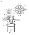
- a valve timing control mechanism 45 includes a sprocket 30, a camshaft 31 and VTC (Valve Timing Controller) 32 and the like.
- the camshaft 31 is driven by a rotation of the sprocket 30.
- the VTC 32 which is interposed between the sprocket 30 and the camshaft 31, can change a relative phase between the sprocket 30 and the camshaft 31 by a hydraulic pressure.
- the VTC 32 is a kind of hydraulic actuator, which mainly includes a VTC housing 32a and a drive plate 32b.
- the sprocket 30 is externally attached onto the VTC housing 32a so as to integrally constitute the VTC housing 32a and the sprocket 30.
- the drive plate 32b is internally attached to the VTC housing 32a, and the drive plate 32b is relatively unrotatably supported on the camshaft 31 penetrating into the shaft center of the VTC housing 32a.
- a space which is formed by an inner circumference surface of the VTC housing 32a and an outer circumference surface of the drive plate 32b, is defined as a first oil chamber 33 and a second oil chamber 34, and the VTC housing 32a is reciprocatd by adjusting a hydraulic balance of a hydraulic oil supplied to the first oil chamber 33 and a second oil chamber 34.
- the relative phase between the sprocket 30 and the camshaft 31 is changed by changing the valve opening degree of a OCV (Oil Control Valve) 35 in response to a control signal from a ECU 50 and by adjusting a hydraulic balance of a hydraulic oil supplied to the first oil chamber 33 and a second oil chamber 34.
- OCV Oil Control Valve
- the timing when the cam 31a fixed on the camshaft 31 and a valve head 25c of an air intake valve 25 are attached to each other, is changed, so as to adjust the timing of closing the air intake valve 25.
- timings of opening and closing an exhaust valve 26 are kept constant, but the valve timing control mechanism 45 may be also applicable to the exhaust valve 26.
- the valve timing control mechanism 45 is constituted so that timings of opening and closing the air intake valve (the valve timing) can be changed by the hydraulic actuator and the like, comprising of the hydraulic actuator and the ECU 50 connected to each other.
- the valve timing control mechanism using the VTC is described, but, for example, the mechanism may be comprised of a rocker arm so as to open and close the air intake valve, multiple cams corresponding to the load, provided at every air intake valve, a hydraulic actuator switching the cams driving the rocker arm in response to the load, and the like.
- a cam profile of the cam may be sterically constituted, and the actuator may be electrically switched, but the valve timing control mechanism applied to the present invention is not limited to the above construction. As described above, the entire construction of the valve timing control mechanism was described.
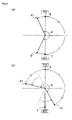
- a valve timing of a commonly-used engine controls the timing as the basis for a phase of a crankshaft, and the valve timing is generally controlled so that the air intake valve 25 is "open” at timing before the TDC (i.e., the point B) (for example, at timing of the point A1) and the air intake valve 25 is "closed” at timing after the BDC (i.e., the point C) (for example, at timing of the D1)
- the air intake valve 25 is "open" at timing before the TDC (i.e., the point B) (for example, at timing of the point A1)
- the air intake valve 25 is "closed” at timing after the BDC (i.e., the point C) (for example, at timing of the D1)
- a phase difference between the "opening " and the "closing" of the air intake valve 25 is held at a constant phase angle ⁇ shown in Figs.
- the valve timing controls the timing, so that the timing of "opening " the air intake valve 25 is, for example, that of the point A2, and the timing of"closing" the air intake valve 25 is that before the BDC (e.g., the timing of the point D2), by accelerating the timings of opening and closing the valve, on the condition that the phase angle ⁇ between the "opening " and the "closing" of the air intake valve 25 is held.
- the timing of closing the air intake valve 25 is that before the BDC (i.e., the timing of the point D2), as intake strokes are continued until the piston comes to the bottom dead center, even after closing the valve, the air breathed in the cylinder is expanded (adiabatically expanded) through the air tight condition, thereby lowering the intake temperature in the cylinder. Also, due to the lowering of the intake temperature in the cylinder, the combustion temperature in the cylinder during the combustion time is lowered, thereby reducing NOx and smokes.
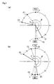
- both of the air intake valves i.e., a first air intake valve 25a and a second air intake valve 25b
- both of the air intake valves are "opened” at timing before the TDC (i.e., the timing of the point B) (for example, the timing of the points E1 and F1)
- the first air intake valve 25a is "closed” at timing after the BDC (i.e., the timing of the point C) (for example, the timing of the point H1)
- the second air intake valve 25b is "closed” at timing before the BDC (for example, the timing of the point G1).
- a phase difference between the "opening " and the "closing" of the first air intake valve 25a is defined as a phase angle ⁇ in Fig. 5 (a)
- a phase difference between the "opening " and the "closing” of the second air intake valve 25b is defined as a phase angle ⁇ in Fig. 5 (a) .
- one of the timings of closing the first air intake valve 25a and the second air intake valve 25b need not necessarily to be before the BDC, the other after the BDC, and the timings of closing both of the air intake valves (i.e., the first air intake valve 25a and the second intake valve 25b) may be those before the BDC (for example, the timings of the points G2 and H2).
- a phase difference, between the timing of "opening” (i.e., the timing of the point F2) and that of "closing” (i.e., the timing of the point H2) of the first air intake valve 25a, is held at the phase angle ⁇ in Fig. 5 (a) .
- a phase difference, between the timing of "opening” (i.e., the timing of the point E2) and that of "closing” (i.e., the timing of the point G2) of the second air intake valve 25b, is held at the phase angle ⁇ in Fig. 5 (a) .
- the timings of closing the first air intake valve 25a and the second air intake valve 25b can be controlled regardless of before and after the BDC, thereby expanding the adjusting range of the adiabatic expansion quantity and finely adjusting the adiabatic expansion quantity.
- an example of one or two air intake valve is described ,but the number of the air intake valve is not limited to it.
- the adjusting range of the adiabatic expansion quantity can be further expanded and the adiabatic expansion quantity can be more finely adjusted.
- an ECU 50 is provided as a control means, so as to realize the valve timing control on the air intake valve according to the embodiment of the present invention.
- the ECU 50 includes a CPU, a RAM and the like, and has an arithmetic processing function, which calculates optimal operating conditions, a memory function, which memorizes a predefined service conditions (the map information and so on).
- the ECU 50 is connected to various sensors in order to detect the operating conditions of the engine, such as an air flow meter 51, a supercharger rotation number sensor 52, a charging pressure sensor 53, an intake temperature sensor 54 and a fuel temperature sensor 55 and the like, as well as a fuel cetane value input portion 56.
- Various signals showing the operating conditions of the engine (the rotation number or the load) and the service conditions are input to the ECU 50, and the ECU 50 performs the arithmetic processing on the basis of the signals.
- the cetane value can be calculated by detecting an angular velocity of a crank angle and calculating an amplitude of the angular velocity, and the cetane value, which is obtained from the angular velocity or other sensors or the like, may be available in an after-mentioned valve timing control.
- the ECU 50 connects devices, such as a valve timing control mechanism 45, an EGR valve 46, a swirl variable valve 47 and the like.
- the ECU 50 issues control signals to devices such as the valve timing control mechanism 45, the EGR valve 46, the swirl variable valve 47 and the like, on the basis of the results of the arithmetic processing, thereby being electrically controlled so as to optimally maintain operation conditions of the engine.
- the EGR exhaust Gas Recirculation
- the EGR is a device, which reduces NOx into the exhaust gas by recirculating a part of the exhaust gas in a combustion chamber and by combusting the intake air with an oxygen concentration lowered, as an air-fuel mixture of an inhaled ambient air and the exhaust gas, so as to slow the combustion and lower the combustion temperature. Because the intake temperature increases with increase in the EGR quantity (i.e., a recirculation volume of the exhaust gas), there is a correlation between the EGR quantity and the timing of closing the air intake valve.
- the intake temperature can be varied by feeding back the EGR quantity from the EGR valve 46 to the ECU 50 and by controlling the valve timing control mechanism 45 corresponding to change in the EGR quantity, so as to adjusting the adiabatic expansion quantity.
- various systems of EGR are heretofore known, but any system can be applicable in the present invention, regardless of formalities of the systems.
- swirl variable valve 47 there is heretofore known a swirl variable valve, as the swirl variable valve 47, that include, for example, a flap valve disc provided in the intake port, driving members such as an actuator provided outside of the intake port or the like, wherein an axis portion which journals the valve disc is penetrated from inside the intake port to outside thereof, and the axis portion connects the driving member via a linkage and so on, so that the valve disc is opened and closed in the intake port in accordance with working conditions of the driving members.
- the swirl variable valve is set up to change the swirl ratio of the inhaled ambient air in the combustion chamber by opening and closing the valve disc so as to change a flow passage area of the intake port.
- the air flow meter 51 is a sensor that detects the intake volume introduced in the cylinder.
- the ECU 50 preliminary memorizes the timing of closing the air intake valve corresponding to the intake volume as a map information, and the ECU 50 outputs the control signal based on the map information to the valve timing control mechanism 45 by feeding back the signal that detected the intake volume to the ECU 50, thereby controlling the timing of closing the air intake valve.
- the ECU 50 memorizes the timing of closing the air intake valve corresponding to an air volume displacement as a map information, by detecting the air volume displacement of the engine, using the supercharger rotation number sensor 52, instead of the air flow meter 51, thereby controlling the valve timing control mechanism 45.
- the charging pressure sensor 53 is a sensor that detects a charging pressure of a supercharger. Generally, it is noted that there is a correlation between the charging pressure and the timing of closing the air intake valve, as the intake temperature increases due to the increase in the charging pressure. Therefore, in the present invention, the signal of the charging pressure detected by the charging pressure sensor 53 is fed back to the ECU 50, and the valve timing control mechanism 45 is controlled to correspond to the change of the charging pressure, thereby adjusting the adiabatic expansion quantity so as to vary the air intake temperature.
- the valve timing control is canceled in accordance with the change of the charging pressure, based on the computational decisions by the ECU 50, thereby returning to a normal intake valve timing or delaying the timing of closing the valve to the BDC.
- the valve timing control is canceled, thereby returning to a normal intake valve timing or delaying the timing of closing the valve to the BDC.
- the intake temperature sensor 54 is a sensor that detects a temperature of inhaled ambient air introduced into the cylinder Because the inhaled ambient air temperature is directly correlated with the intake temperature, the signal of the inhaled ambient air temperature detected by the intake temperature sensor 54 is fed back to the ECU 50, and the valve timing control mechanism 45 is proportionally-controlled, in proportion to the change of the inhaled ambient air temperature, thereby adjusting the adiabatic expansion quantity so as to vary the air intake temperature.
- the valve timing control is canceled in accordance with the change of the inhaled ambient air temperature, based on the computational decisions by the ECU 50, thereby returning to a normal intake valve timing or delaying the timing of closing the valve to the BDC.
- the fuel temperature sensor 55 is a sensor that detects a temperature of the fuels injected into the cylinder. Because the fuel temperature is correlated with the combustion temperature, the signal of the fuel temperature detected by the fuel temperature sensor 55 is fed back to the ECU 50, and the valve timing control mechanism 45 is controlled, in accordance with the change of the fuel temperature, thereby adjusting the adiabatic expansion quantity so as to vary the air intake temperature.
- valve timing control is canceled in accordance with the change of the fuel temperature, based on the computational decisions by the ECU 50, thereby returning to a normal intake valve timing or delaying the timing of closing the valve to the BDC.
- the fuel cetane value input portion 56 is a means for inputting a cetane value of the fuels used into the ECU 50 and memorizing it as a service condition and includes a display and a numeric keypad and the like.
- the cetane values of the fuels available from around the world are widely variable, but the fuel cetane value is correlated with the combustion temperature. Therefore, in the present invention, the fuel cetane value used for practical purposes is input into the ECU 50 as the service condition or alternatively, a detected value is input into the ECU 50 and memorized, and the valve timing control mechanism 45 is controlled in accordance with the fuel cetane value, thereby adjusting the adiabatic expansion quantity so as to vary the air intake temperature. As described above, the valve timing control on the air intake valve according to an embodiment of the present invention was described.
- Fig. 7 shows experimentally ascertained data on the changes of the respective concentrations of smokes, CO (carbon monoxide) and NOx (nitrogen oxide) in the exhaust air , due to the change of the intake air temperature in the respective conditions at the time when the present invention is applied and not applied.
- the injector having a group of injection holes had a problem of increasing in the smokes with increase in the intake air temperature, but, after the time of application of the present invention, it is confirmable that the increase in the smokes is inhibited, even when the intake air temperature increases from about 10 degrees C to about 25 degrees C.
- the intake air temperature is in a practicable area by application of the present invention, the problem of increasing the smokes in the exhaust gas due to the change in the intake air temperature, facing the injector having a group of injection holes, can be solved.
- the injector having a group of injection holes causes the problem of increasing NOx, it is confirmable that the amount ofNOx generation is reduced up to about two thirds, compared to that at the inapplicable time of the present invention. In other words, when the intake air temperature is in a practicable area by application of the present invention, the problem of increasing NOx facing the injector having a group of injection holes can be solved.
- the air intake valve 25 is controlled to close, at timing before BDC (at timing when the piston comes to the bottom dead center), by the ECU 50, which controls the timing of closing the air intake valve 25, based on operating conditions of the engine. Accordingly, the intake temperature in the cylinder can be lowered and the combustion temperature can be lowered, due to the effect of intake air adiabatic expansion. The generation of the smokes and THC can be also reduced.
- the ECU 50 electrically controls the timing of closing the air intake valve 25. Accordingly, the accurate and detailed valve timing control can be performed, in accordance with operation conditions.
- the timing of closing the air intake valve 25 is controlled base on the EGR quantity fed back from the EGR valve 46 to the ECU 50. Accordingly, the adequate valve timing control can be performed by feeding back the intake air temperature change by the EGR valve 46 to the ECU 50
- the ECU 50 preliminary memorizes the map information corresponding to the intake volume or the air volume displacement and controls the timing of closing the air intake valve 25, based on the intake volume or the air volume displacement detected by the air flow meter 51 or the supercharger rotation number sensor 52. Accordingly, the adequate valve timing control can be performed by feeding back the intake air volume to the ECU 50.
- Multiple air intake valves 25 are provided per single cylinder, and the respective valves 25a, 25b of them are controlled so that they are closed at different timings by the ECU 50. Accordingly, the timing, when the effect of intake air adiabatic expansion is acquired, can be expanded, and a detailed valve timing control can be performed.
- the ECU 50 controls the swirl variable valve 47 to increase the swirl ratio.
- the combustion efficiency can be further improved by increasing the swirl ratio, with increase in the intake air adiabatic expansion quantity.
- the ECU 50 controls the timing of closing the air intake valve 25 in response to the charging pressure detected by the charging pressure sensor 53.
- the adequate valve timing control can be performed by relating the intake adiabatic expansion quantity to the charging pressure.
- the ECU 50 controls the timing of closing the air intake valve 25 in response to the intake temperature detected by the intake temperature sensor 54.
- the adequate valve timing control can be performed by relating the intake adiabatic expansion quantity to the intake temperature.
- the ECU 50 controls the timing of closing the air intake valve 25 in response to the fuel temperature detected by the fuel temperature sensor 55.
- the adequate valve timing control can be performed by relating the intake adiabatic expansion quantity to the fuel temperature.
- the ECU 50 controls the timing of closing the air intake valve 25 in response to the fuel cetane value detected by the fuel cetane value input portion.
- the adequate valve timing control can be performed by relating the intake adiabatic expansion quantity to the fuel cetane value.
- the ECU 50 controls the timing of closing the air intake valve 25 so that it is closed at timing after the BDC (at timing when the piston comes to the bottom dead center), base on any of the detected value of the charging pressure by the charging pressure sensor 53, that of the intake temperature by the intake temperature sensor 54, or that of the fuel temperature by the fuel temperature sensor 55, or alternatively, based on the combination of the respective detected values of the charging pressure, the intake temperature and the fuel temperature. Accordingly, during the operating conditions that are not suitable to the valve timing control, the valve timing control can be canceled and be automatically switched to the normal control.
- the technologies according to the present invention can be widely applicable in the common-rail diesel engine for use in various applications such as ships, automobiles and the like.
Landscapes
- Engineering & Computer Science (AREA)
- Mechanical Engineering (AREA)
- General Engineering & Computer Science (AREA)
- Chemical & Material Sciences (AREA)
- Combustion & Propulsion (AREA)
- Output Control And Ontrol Of Special Type Engine (AREA)
- Electrical Control Of Air Or Fuel Supplied To Internal-Combustion Engine (AREA)
- Fuel-Injection Apparatus (AREA)
- Combined Controls Of Internal Combustion Engines (AREA)
Applications Claiming Priority (2)
| Application Number | Priority Date | Filing Date | Title |
|---|---|---|---|
| JP2006202572A JP2008025551A (ja) | 2006-07-25 | 2006-07-25 | ディーゼルエンジンのバルブタイミング制御方法 |
| PCT/JP2007/061384 WO2008012992A1 (en) | 2006-07-25 | 2007-06-05 | Method of controlling valve timing of diesel engine |
Publications (2)
| Publication Number | Publication Date |
|---|---|
| EP2048338A1 true EP2048338A1 (de) | 2009-04-15 |
| EP2048338A4 EP2048338A4 (de) | 2010-03-03 |
Family
ID=38981307
Family Applications (1)
| Application Number | Title | Priority Date | Filing Date |
|---|---|---|---|
| EP07744736A Withdrawn EP2048338A4 (de) | 2006-07-25 | 2007-06-05 | Verfahren zur ventilsteuerung eines dieselmotors |
Country Status (8)
| Country | Link |
|---|---|
| US (1) | US8042516B2 (de) |
| EP (1) | EP2048338A4 (de) |
| JP (1) | JP2008025551A (de) |
| CN (1) | CN101495734B (de) |
| BR (1) | BRPI0714675A2 (de) |
| CA (1) | CA2658930C (de) |
| RU (1) | RU2419725C2 (de) |
| WO (1) | WO2008012992A1 (de) |
Cited By (1)
| Publication number | Priority date | Publication date | Assignee | Title |
|---|---|---|---|---|
| EP2538042A4 (de) * | 2010-02-19 | 2014-08-20 | Yanmar Co Ltd | Dieselmotor |
Families Citing this family (20)
| Publication number | Priority date | Publication date | Assignee | Title |
|---|---|---|---|---|
| FR2915246B1 (fr) * | 2007-04-17 | 2010-09-03 | Peugeot Citroen Automobiles Sa | Procede et systeme de demarrage et de ralenti a froid d'un moteur a combustion interne. |
| JP5169895B2 (ja) * | 2009-02-12 | 2013-03-27 | トヨタ自動車株式会社 | 内燃機関の制御装置 |
| JP5185910B2 (ja) * | 2009-10-16 | 2013-04-17 | 三菱重工業株式会社 | ミラーサイクルエンジン |
| JP2011163135A (ja) * | 2010-02-04 | 2011-08-25 | Yanmar Co Ltd | エンジン |
| EP2532846B1 (de) * | 2010-02-04 | 2015-04-08 | Yanmar Co., Ltd. | Motor |
| JP4902754B2 (ja) * | 2010-02-04 | 2012-03-21 | ヤンマー株式会社 | エンジン |
| WO2012063362A1 (ja) * | 2010-11-12 | 2012-05-18 | トヨタ自動車株式会社 | 内燃機関の制御装置 |
| FI124121B (fi) * | 2010-12-01 | 2014-03-31 | Wärtsilä Finland Oy | Polttomoottorin ohjausmenetelmä ja polttomoottori |
| JP5573701B2 (ja) * | 2011-01-24 | 2014-08-20 | トヨタ自動車株式会社 | 内燃機関 |
| US8851045B2 (en) * | 2011-03-31 | 2014-10-07 | Wisconsin Alumni Research Foundation | Engine combustion control at low loads via fuel reactivity stratification |
| US9151241B2 (en) | 2012-07-27 | 2015-10-06 | Caterpillar Inc. | Reactivity controlled compression ignition engine operating on a Miller cycle with low pressure loop exhaust gas recirculation system and method |
| US9051887B2 (en) | 2012-07-27 | 2015-06-09 | Caterpillar Inc. | System and method for adjusting fuel reactivity |
| US20140026873A1 (en) * | 2012-07-27 | 2014-01-30 | Caterpillar Inc. | Variable Miller Cycle for Reactivity Controlled Compression Ignition Engine and Method |
| US20140032081A1 (en) * | 2012-07-27 | 2014-01-30 | Caterpillar Inc. | Dual Mode Engine Using Two or More Fuels and Method for Operating Such Engine |
| US8991358B2 (en) | 2012-07-27 | 2015-03-31 | Caterpillar Inc. | Reactivity controlled compression ignition engine with exhaust gas recirculation |
| US9038582B2 (en) | 2012-07-27 | 2015-05-26 | Caterpillar Inc. | Split-cycle, reactivity controlled compression ignition engine and method |
| US9222429B2 (en) | 2013-02-14 | 2015-12-29 | Caterpillar Inc. | Engine control system having a cam phaser |
| DE102014211160A1 (de) | 2014-06-11 | 2015-12-17 | Volkswagen Aktiengesellschaft | Verfahren und Steuereinheit zum Ausführen eines Gaswechsels in einem Zylinder einer Verbrennungskraftmaschine sowie Verbrennungskraftmaschine mit einer solchen Steuereinheit |
| EP3245394B1 (de) * | 2014-12-08 | 2019-08-07 | Wärtsilä Finland Oy | Verfahren zur kontrolle der betätigung eines einlassventilsystems und ein einlassventilkontrolsystem |
| DE102015013794A1 (de) * | 2015-10-22 | 2017-04-27 | Man Truck & Bus Ag | Verfahren zum Betreiben einer Brennkraftmaschine, insbesondere eines Dieselmotors |
Family Cites Families (21)
| Publication number | Priority date | Publication date | Assignee | Title |
|---|---|---|---|---|
| JPS4517486Y1 (de) * | 1966-12-06 | 1970-07-17 | ||
| JPS5845953U (ja) * | 1981-09-21 | 1983-03-28 | 日立造船株式会社 | 燃料噴射弁 |
| JPS60171958A (ja) | 1984-02-16 | 1985-09-05 | Tsudakoma Ind Co Ltd | 布巻ロ−ル交換装置のオ−トドッフィング機構 |
| JPS60171958U (ja) * | 1984-04-24 | 1985-11-14 | 日産自動車株式会社 | サツクレス式ホ−ル型燃料噴射ノズル |
| SU1267025A1 (ru) * | 1984-11-23 | 1986-10-30 | Центральный Ордена Трудового Красного Знамени Научно-Исследовательский И Проектно-Конструкторский Институт Механизации И Энергетики Лесной Промышленности | Способ работы дизел |
| JP3209015B2 (ja) | 1994-09-02 | 2001-09-17 | 三菱自動車工業株式会社 | 制動エネルギ回収装置付車両用エンジン |
| JP3453215B2 (ja) | 1995-03-24 | 2003-10-06 | 日産ディーゼル工業株式会社 | ディーゼルエンジンの燃料噴射ノズル |
| JP3298371B2 (ja) | 1995-07-28 | 2002-07-02 | 日産自動車株式会社 | ディーゼルエンジンの制御装置 |
| JPH10212910A (ja) | 1997-01-29 | 1998-08-11 | Mikuni Corp | バルブタイミング調整装置 |
| JPH10325324A (ja) * | 1997-05-26 | 1998-12-08 | Isuzu Motors Ltd | ディーゼルエンジン |
| JP3468135B2 (ja) | 1998-12-11 | 2003-11-17 | 三菱自動車工業株式会社 | ベーン式カム位相可変装置 |
| JP2002188474A (ja) * | 2000-12-15 | 2002-07-05 | Mazda Motor Corp | ターボ過給機付きディーゼルエンジンの制御装置 |
| JP4461617B2 (ja) * | 2000-12-15 | 2010-05-12 | マツダ株式会社 | ディーゼルエンジンの燃焼制御装置 |
| EP1387074A1 (de) | 2001-05-09 | 2004-02-04 | Hitachi, Ltd. | Steuerung für verbrennungsmotor mit direkteinspritzung |
| JP2003090272A (ja) | 2001-09-18 | 2003-03-28 | Mitsubishi Heavy Ind Ltd | ディーゼル機関の燃焼制御方法及びその装置 |
| JP4075550B2 (ja) * | 2002-09-24 | 2008-04-16 | トヨタ自動車株式会社 | 可変動弁機構を有する内燃機関におけるノッキング制御 |
| CN1434193A (zh) * | 2003-02-27 | 2003-08-06 | 上海交通大学 | 实现柴油机低排放均质燃烧的方法 |
| JP2004360459A (ja) | 2003-05-30 | 2004-12-24 | Honda Motor Co Ltd | 内燃機関のバルブタイミング制御装置 |
| JP4005941B2 (ja) * | 2003-06-03 | 2007-11-14 | 株式会社日立製作所 | 筒内噴射エンジンの燃焼制御装置及び燃焼制御方法 |
| JP4251123B2 (ja) * | 2003-11-04 | 2009-04-08 | 株式会社デンソー | 内燃機関 |
| JP4155251B2 (ja) | 2004-09-02 | 2008-09-24 | 株式会社デンソー | 燃料噴射ノズル |
-
2006
- 2006-07-25 JP JP2006202572A patent/JP2008025551A/ja active Pending
-
2007
- 2007-06-05 CA CA2658930A patent/CA2658930C/en not_active Expired - Fee Related
- 2007-06-05 EP EP07744736A patent/EP2048338A4/de not_active Withdrawn
- 2007-06-05 CN CN2007800279287A patent/CN101495734B/zh not_active Expired - Fee Related
- 2007-06-05 WO PCT/JP2007/061384 patent/WO2008012992A1/ja not_active Ceased
- 2007-06-05 BR BRPI0714675-2A patent/BRPI0714675A2/pt not_active IP Right Cessation
- 2007-06-05 US US12/374,904 patent/US8042516B2/en not_active Expired - Fee Related
- 2007-06-05 RU RU2009106459/06A patent/RU2419725C2/ru not_active IP Right Cessation
Cited By (1)
| Publication number | Priority date | Publication date | Assignee | Title |
|---|---|---|---|---|
| EP2538042A4 (de) * | 2010-02-19 | 2014-08-20 | Yanmar Co Ltd | Dieselmotor |
Also Published As
| Publication number | Publication date |
|---|---|
| BRPI0714675A2 (pt) | 2013-02-19 |
| RU2419725C2 (ru) | 2011-05-27 |
| CA2658930C (en) | 2012-07-10 |
| JP2008025551A (ja) | 2008-02-07 |
| CN101495734A (zh) | 2009-07-29 |
| WO2008012992A1 (en) | 2008-01-31 |
| US8042516B2 (en) | 2011-10-25 |
| CN101495734B (zh) | 2013-01-30 |
| CA2658930A1 (en) | 2008-01-31 |
| US20090314264A1 (en) | 2009-12-24 |
| EP2048338A4 (de) | 2010-03-03 |
| RU2009106459A (ru) | 2010-08-27 |
Similar Documents
| Publication | Publication Date | Title |
|---|---|---|
| US8042516B2 (en) | Method of controlling valve timing of diesel engine | |
| US6612292B2 (en) | Fuel injection control for diesel engine | |
| US6209516B1 (en) | Control system and control method for diesel engine | |
| US6807929B2 (en) | Engine valve actuation system and method | |
| Urata et al. | A study of vehicle equipped with non-throttling SI engine with early intake valve closing mechanism | |
| EP2179158B1 (de) | Verfahren und vorrichtung zur steuerung einer brennkraftmaschine | |
| KR20060051868A (ko) | 엔진 | |
| JP2008303763A (ja) | 内燃機関の排気浄化制御装置 | |
| CN100439680C (zh) | 四冲程预混压缩点火式内燃机的控制装置和控制方法 | |
| US6460491B1 (en) | Method of water/fuel co-injection for emissions control during transient operating conditions of a diesel engine | |
| Schwoerer et al. | Lost-motion VVA systems for enabling next generation diesel engine efficiency and after-treatment optimization | |
| JP2009216059A (ja) | 内燃機関の制御装置 | |
| EP1764490B1 (de) | Verfahren und vorrichtung zur steuerung einer brennkraftmaschine | |
| US7000586B2 (en) | Control device for compression ignition operation of internal combustion engine | |
| JP2008303744A (ja) | 内燃機関の制御装置 | |
| JP2005069143A (ja) | 予混合圧縮自着火内燃機関 | |
| JP3228036B2 (ja) | 弁開閉機構付きエンジン | |
| JP4900296B2 (ja) | 内燃機関の位相可変動弁機構 | |
| JP4559915B2 (ja) | 排気ガス再循環装置 | |
| JP4946345B2 (ja) | 内燃機関の制御装置 | |
| US7047920B2 (en) | Engine valve actuation system and method for controlling white smoke | |
| JPH11159357A (ja) | ディーゼルエンジンの排気浄化装置 | |
| JP2002030992A (ja) | 内燃機関の排気浄化装置 | |
| JP2010203352A (ja) | ディーゼルエンジンの燃焼制御方法およびディーゼルエンジン | |
| JP2001214815A (ja) | 内燃機関の排気装置 |
Legal Events
| Date | Code | Title | Description |
|---|---|---|---|
| PUAI | Public reference made under article 153(3) epc to a published international application that has entered the european phase |
Free format text: ORIGINAL CODE: 0009012 |
|
| 17P | Request for examination filed |
Effective date: 20090225 |
|
| AK | Designated contracting states |
Kind code of ref document: A1 Designated state(s): AT BE BG CH CY CZ DE DK EE ES FI FR GB GR HU IE IS IT LI LT LU LV MC MT NL PL PT RO SE SI SK TR |
|
| AX | Request for extension of the european patent |
Extension state: AL BA HR MK RS |
|
| RIN1 | Information on inventor provided before grant (corrected) |
Inventor name: TSUDA, TOMOYUKI Inventor name: SHINOHARA, YUKIHIRO Inventor name: ASAI, GOU Inventor name: KAWABE, TAKAO Inventor name: SHIMIZU, KOUJI Inventor name: TAKAHATA, TERUMITSU Inventor name: NOMURA, HIDENORI Inventor name: TAKAHASHI, TAKESHI |
|
| DAX | Request for extension of the european patent (deleted) | ||
| RBV | Designated contracting states (corrected) |
Designated state(s): DE FR GB IT NL SE |
|
| A4 | Supplementary search report drawn up and despatched |
Effective date: 20100129 |
|
| 17Q | First examination report despatched |
Effective date: 20110627 |
|
| STAA | Information on the status of an ep patent application or granted ep patent |
Free format text: STATUS: THE APPLICATION IS DEEMED TO BE WITHDRAWN |
|
| 18D | Application deemed to be withdrawn |
Effective date: 20111108 |