EP2049740B1 - Unité améliorée de distribution d'eau mélangée - Google Patents
Unité améliorée de distribution d'eau mélangée Download PDFInfo
- Publication number
- EP2049740B1 EP2049740B1 EP07787759.5A EP07787759A EP2049740B1 EP 2049740 B1 EP2049740 B1 EP 2049740B1 EP 07787759 A EP07787759 A EP 07787759A EP 2049740 B1 EP2049740 B1 EP 2049740B1
- Authority
- EP
- European Patent Office
- Prior art keywords
- unit
- mixer
- tubular
- mouth
- inlet
- Prior art date
- Legal status (The legal status is an assumption and is not a legal conclusion. Google has not performed a legal analysis and makes no representation as to the accuracy of the status listed.)
- Active
Links
Images


Classifications
-
- E—FIXED CONSTRUCTIONS
- E03—WATER SUPPLY; SEWERAGE
- E03C—DOMESTIC PLUMBING INSTALLATIONS FOR FRESH WATER OR WASTE WATER; SINKS
- E03C1/00—Domestic plumbing installations for fresh water or waste water; Sinks
- E03C1/02—Plumbing installations for fresh water
- E03C1/04—Water-basin installations specially adapted to wash-basins or baths
- E03C1/042—Arrangements on taps for wash-basins or baths for connecting to the wall
Definitions
- the invention concerns a perfected unit for dispensing mixed water, particularly suited to be used in sanitary water dispensing systems.
- the units for dispensing mixed water substantially comprise a mixer provided with ways for the inlet of hot and cold water coming from the water mains, with an outlet for the outflow of the mixed water connected to a dispenser and with one or more pins, each one of which is connected to a manoeuvring handle that allows the user to control the dispensed water flow.
- a mixer provided with ways for the inlet of hot and cold water coming from the water mains, with an outlet for the outflow of the mixed water connected to a dispenser and with one or more pins, each one of which is connected to a manoeuvring handle that allows the user to control the dispensed water flow.
- this is positioned at a certain distance from the mixer, like for example in the case of a shower head, this is connected to the mixer via a rigid or flexible pipe, depending on the case.
- the compartment created in the wall is sealed with mortar, taking care that the pin or pins for application of the handle or handles project/s from the wall.
- the user also has to suffer the nuisance deriving from the execution of demolition work inside his/her house/flat.
- This embodiment avoids the need to carry out demolition work when the mixer must be replaced, but still poses some acknowledged drawbacks.
- the support flange that closes the box-shaped body is constructed in such a way as to be able to house a specific type of mixer that, therefore, cannot be replaced with any other type of mixer chosen by the user, even if produced by the same manufacturer.
- the documents DE 18 11 936 A1 and DE 38 26 064 A1 disclose arrangements for dispensing mixed water wherein the connection between a manifold unit for the distribution of cold and hot water and the dispensing unit is realized in telescopic form to adapt the arrangement to different depths of the wall where the arrangement has to be installed.
- the document DE 1 809 022 describes a dispensing unit for mixed water according to the preamble of claim 1, provided with a telescopic connection between manifold unit and dispensing unit.
- the manifold unit is realized by two elbow connectors which are only fixed in a determined position after the connection to the dispensing unit has been taken place. This renders the system independent from the position of the feed lines in the wall.
- the connection is effected by coupling nuts with squeeze-type gaskets. Supplemental security is given by an additional screw.
- the present invention aims to overcome the drawbacks listed above and to simplify the connection of the ends.
- the dispensing unit that is the subject of the invention allows for replacement of the mixer with no need for demolition work, it makes it possible to reduce maintenance times and costs.
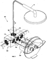
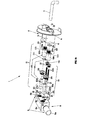
- the dispensing unit for mixed water that is the subject of the invention is represented in a schematic axonometric view in Figure 1 and in an exploded axonometric view in Figure 1b , where it is indicated as a whole by 1.
- a mixer unit 2 provided with a pair of manoeuvring handles 3 at the disposal of the user, in which there are a first inlet way 4 for hot water, a second inlet way 5 for cold water and an outlet way 6 for the mixed water to be conveyed towards a dispenser 7.
- Each handle 3 manoeuvres a tap 4a, 5a to modulate the flows that converge in the outlet way 6 through the inlet ways 4, 5.
- the dispensing unit 1 also comprises a manifold unit 8 provided with a plurality of mouths 12, separate from the mixer unit 2 and interposed between a water supply network 9 and the mixer unit 2, to which it is connected mechanically through adjustable positioning and fixing means 10 and hydraulically through tubular units 11 that connect at least each one of the inlet ways 4, 5 of the mixer unit 2 to a corresponding mouth 12 of the manifold unit 8.
- a manifold unit 8 provided with a plurality of mouths 12, separate from the mixer unit 2 and interposed between a water supply network 9 and the mixer unit 2, to which it is connected mechanically through adjustable positioning and fixing means 10 and hydraulically through tubular units 11 that connect at least each one of the inlet ways 4, 5 of the mixer unit 2 to a corresponding mouth 12 of the manifold unit 8.
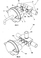
- Figures from 3 to 8 show that the dispenser 7 is directly connected to the outlet way 6 of the mixer unit 2, while the manifold unit 8 comprises a prismatic body 8a in which the mouths 12 comprise:
- the dispensing unit 1 just described is suited to be used for applications of the type represented in Figure 1a where, for example, there is a bathtub V or a basin (not represented).
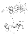
- the dispensing unit 1 shown in Figure 1 a is visible in the cross sections of Figures 3 and 4 , in which it can be observed that the manifold unit 8 is inserted in a compartment A created in the wall B where it is stable owing to the connection to the cold and hot water pipes 9b and 9a respectively, which make up the water distribution network 9, and due to the fact that it is fixed with mortar.
- the mixer unit 2 instead, is arranged against the wall B, being connected to the manifold unit 8 hydraulically through the above mentioned tubular units 11 and mechanically through the adjustable positioning and fixing means 10.
- the mixer unit 2 is of the type known per se and can be provided with two manoeuvring handles 3 as shown in the drawings or with a single manoeuvring handle.
- tubular units 19 and 20 indicated as a whole by 11, it can be observed, in particular in Figure 1b , that:
- Each tubular element 19a, 20a is telescopically fitted inside a corresponding tubular body 19b, 20b as shown in Figure 3 and they achieve mutual water tightness through the interposition of one or more annular gaskets 19c, 20c with radial seal.
- each one of them comprises a spherical head 21a, 23a created at one end of the respective tubular element 19a, 20a, which is housed in a spherical seat 21 b, 23b made in the corresponding mouth 15, 18 of the manifold unit 8 and a threaded nipple 25, 26 arranged so as to pass through the corresponding tubular element 19a, 20a for connection.
- a gasket 27, 28 is interposed between each spherical seat 21b, 23b and the spherical head 21a, 23a to ensure water tightness.
- each of them comprises a threaded tubular area with lowered diameter 22a, 24a created at one end of each tubular body 19b, 20b which is coupled with a nut screw present in the respective way 4, 5, with the interposition of a gasket 29, 30.
- each tubular body 19b, 20b there is a prismatic profile 32a, 32b for coupling a manoeuvring fork wrench.
- the adjustable positioning and fixing means 10 comprise two screws 31 each of which is associated with the manifold 8 via first connection means 33 and to the mixer 2 via second connection means 35.
- each of them comprises a spherical head 33a created at one end of each screw 31 that is housed in a housing with spherical profile 33b made in the manifold body 8 and a threaded nipple 37 that connects the spherical head 33a in the spherical housing 33b, similarly to the already described connection of each tubular element 19a, 20a to the manifold body 8.
- the second connection means 35 each of them comprises a nut 35a arranged in a through hole 35b made in the mixer 2, which is coupled at the end 33c of the screw 31 arranged on the opposite side of the spherical head 33a and inserted in the through hole 35b.
- the manifold unit 8 is then fixed with mortar according to the known technique.
- the mixer unit 2 is assembled, by fitting each tubular element 19a, 20a in the corresponding tubular body 19b, 20b and at the same time inserting the ends 33c of the screws 31 in the holes 35b of the mixer 2.
- the nuts 35a are locked from the outside, using a suitable manual tool and thus obtaining the stability of the mixer unit 2 with respect to the manifold unit 8 and against the wall B.
- the dispensing unit of the invention in a construction variant, is represented in Figures 2 and 2b , while an application of the same is shown in Figure 2a , where it is indicated as a whole by 100.
- the manifold unit 108 also comprises:
- Figures 10 and 12 show an embodiment of the dispensing unit indicated by 100.
- tubular units 19, 20 and 200 being telescopic, allow the mixer unit 2 and 102 to be easily connected and disconnected after installing the corresponding manifold unit 8 and 108 and that their mutual fastening takes place in a simple way, by locking the nuts 35a at the ends of the screws 31 as previously described.
- the dispensing unit 1 is suited for application to a wall as shown in Figure 1 a and in general for all the applications where the dispenser 7 is associated with the mixer unit 2.
- the dispensing unit 100 is suitable for applications where the dispenser 70 is in a remote position, for example in a shower system T as shown in Figure 2a .
- the particular configuration with spherical head of the tubular units 11 and 110 and of the adjustable positioning and fixing means 10 ensures the articulation of the mixer unit 2; 102 with respect to the manifold unit 8; 108 during the assembly stage, in such a way as to recover any lack of parallelism.
- the dispensing unit of the invention in both the embodiments described, achieves all the set objects.
- the presence of the tubular units and of the adjustable positioning and fixing means with spherical head allows any misalignment between the manifold unit and the mixer unit to be corrected with no need for the installer to worry about their alignment during installation.
- the mixer unit can be replaced with no need for building work.
- the mixer can be easily replaced with another one whose shape is more appealing for the user.
Landscapes
- Health & Medical Sciences (AREA)
- Life Sciences & Earth Sciences (AREA)
- Engineering & Computer Science (AREA)
- Hydrology & Water Resources (AREA)
- Public Health (AREA)
- Water Supply & Treatment (AREA)
- Domestic Plumbing Installations (AREA)
Claims (8)
- Groupe de distribution (1; 100) d'eau mélangée comprenant un groupe mélangeur (2; 102) doté d'au moins une poignée de manoeuvre (3) à la disposition de l'utilisateur et ayant une première voie d'entrée (4) pour l'eau chaude, une deuxième voie d'entrée (5) pour l'eau froide et une voie de sortie (6; 60) pour transporter l'eau mélangée vers un distributeur (7; 70); comprenant également un groupe collecteur (8; 108) doté d'une pluralité de bouches (12), séparé dudit groupe mélangeur (2; 102) et interposé entre un réseau hydrique d'alimentation (9) et ledit groupe mélangeur (2; 102) auquel il est relié mécaniquement par des moyens réglables de positionnement et de fixation (10) et hydrauliquement par des groupes tubulaires (11, 19, 20; 110; 200) qui relient au moins chacune desdites voies d'entrée (4; 5) dudit groupe mélangeur (2; 102) à une bouche correspondante desdites bouches (12) dudit groupe collecteur (8; 108) où chacun desdits groupes tubulaires (11, 19, 20; 110, 200) comprend un élément tubulaire (19a; 20a) engagé par des éléments d'union (21; 23) dans une bouche correspondante (15; 18; 160) dudit groupe collecteur (8; 108) et un corps tubulaire (19b; 20b) engagé par des moyens d'union (22; 24) dans une voie correspondante (4; 5; 60) dudit mélangeur (2; 102), chacun desdits éléments tubulaires (19a; 20a) étant accouplé de manière télescopique dans un corps tubulaire correspondant (19b; 20b),
caractérisé en ce que chacun desdits premiers éléments d'union (21; 23), comprend:- une tête sphérique (21 a; 23a) créée sur une extrémité de l'élément tubulaire correspondant (19a; 20a);- un siège sphérique (21b; 23b) réalisé dans la bouche correspondante (15; 18) dudit groupe collecteur (8; 108) qui loge ladite tête sphérique (21 a; 23a);- un raccord fileté (25; 26) pour l'accouplement de ladite tête sphérique (21 a; 23a) dans ledit siège sphérique (21b; 23b),et en ce que lesdits moyens réglables de fixation et de positionnement (10) comprennent deux ou plusieurs vis (31) chacune de celles-ci est associée avec ledit collecteur (8; 108) par de premiers moyens de connexion (33) et avec ledit mélangeur (2; 102) par de deuxièmes moyens de connexion (35),
où chacun desdits premiers moyens de connexion (33) comprend:- une tête sphérique (33a) créée sur une extrémité de ladite vis (31);- un logement sphérique (33b) créé dans ledit collecteur (8; 108);- un raccord fileté (37) pour l'accouplement de ladite tête sphérique (33a) dans ledit logement sphérique (33b),et où chacun desdits deuxièmes moyens de connexion (35) comprend un écrou (35a) disposé dans un trou passant (35b) réalisé dans ledit mélangeur (8; 108) et visé sur une extrémité (33c) de ladite vis (31) insérée dans ledit trou passant (35b). - Groupe de débit (1) selon la revendication 1), caractérisé en ce que ledit groupe collecteur (8) comprend:- une première bouche d'entrée (13) reliée à un tuyau d'alimentation d'eau chaude (9a) appartenant audit réseau hydrique d'alimentation (9);- un premier canal (14) qui met en communication ladite première bouche d'entrée (13) avec une première bouche de sortie (15);- une deuxième bouche d'entrée (16) reliée à un tuyau d'alimentation d'eau froide (9b) appartenant audit réseau hydrique d'alimentation (9);- un deuxième canal (17) qui met en communication ladite deuxième bouche d'entrée (16) avec une deuxième bouche de sortie (18);et où lesdits groupes tubulaires (11) comprennent:- un premier groupe tubulaire (19) qui relie ladite première bouche de sortie (15) dudit groupe collecteur (8) à ladite première voie d'entrée (4) dudit groupe mélangeur (2);- un deuxième groupe tubulaire (20) qui relie ladite deuxième bouche de sortie (18) dudit groupe collecteur (8) à ladite deuxième voie d'entrée (5) dudit groupe mélangeur (2);ledit distributeur (7) étant relié directement à ladite voie de sortie (6) pour ladite eau mélangée provenant dudit mélangeur (2).
- Groupe de débit (100) selon la revendication 1), caractérisé en ce que ledit groupe collecteur (108) comprend:- une première bouche d'entrée (13) reliée à un tuyau d'alimentation d'eau chaude (9a) appartenant audit réseau hydrique d'alimentation (9);- un premier canal (14) qui met en communication ladite première bouche d'entrée (13) avec une première bouche de sortie (15);- une deuxième bouche d'entrée (16) reliée à un tuyau d'alimentation d'eau froide (9b) appartenant audit réseau hydrique d'alimentation (9);- un deuxième canal (17) qui met en communication ladite deuxième bouche d'entrée (16) avec une deuxième bouche de sortie (18);- une troisième bouche d'entrée (160) reliée à ladite voie de sortie (60) de ladite eau mélangée provenant dudit groupe mélangeur (102);- un troisième canal (170) qui met en communication ladite troisième bouche d'entrée (160) avec une troisième bouche de sortie (180) de ladite eau mélangée,et où lesdits groupes tubulaires (110) comprennent:- un premier groupe tubulaire (19) qui relie ladite première bouche de sortie (15) dudit groupe collecteur (108) à ladite première voie d'entrée (4) dudit groupe mélangeur (102);- un deuxième groupe tubulaire (20) qui relie ladite deuxième bouche de sortie (18) dudit groupe collecteur (108) à ladite deuxième voie d'entrée (5) dudit groupe mélangeur (102);- un troisième groupe tubulaire (200) qui relie ladite troisième bouche d'entrée (160) dudit groupe collecteur (108) à ladite voie de sortie (60) de ladite eau mélangée provenant dudit mélangeur (102);où un tuyau (190) relie ladite troisième bouche de sortie (180) dudit groupe collecteur (108) audit distributeur (70).
- Groupe de débit (1; 100) selon la revendication 1), caractérisé en ce qu'entre chacun desdits éléments tubulaires (19a; 20a) et ledit corps tubulaire correspondant (19b; 20b) au moins un joint d'étanchéité annulaire (19c; 20c) radial est interposé.
- Groupe de débit (1 ; 100) selon la revendication 1), caractérisé en ce qu'il comprend au moins un joint (27; 28) interposé entre ladite tête sphérique (21 a; 23a) et ledit siège sphérique (21b; 23b).
- Groupe de débit (1 ; 100) selon la revendication 1), caractérisé en ce que ledit raccord (25; 26) est disposé de manière passante dans ledit élément tubulaire (19a; 20a).
- Groupe de débit (1 ; 100) selon la revendication 1), caractérisé en ce que chacun desdits moyens d'union (22; 24) comprend une zone tubulaire filetée avec diamètre abaissé (22a; 24a) réalisée dans une extrémité de chaque corps tubulaire (19b; 20b) qui s'accouple dans une vis-mère correspondante présente dans la voie correspondante (4; 5).
- Groupe de débit (1 ; 100) selon la revendication 7), caractérisé en ce qu'il comprend au moins un joint (29; 30) interposé entre ladite zone tubulaire filetée avec diamètre abaissé (22a; 24a) de chaque élément tubulaire (19a; 20a) et ladite vis-mère correspondante.
Applications Claiming Priority (2)
| Application Number | Priority Date | Filing Date | Title |
|---|---|---|---|
| ITVI20060251 ITVI20060251A1 (it) | 2006-08-09 | 2006-08-09 | Gruppo perfezionato per l'egorazione di acqua miscelata. |
| PCT/EP2007/057504 WO2008017578A1 (fr) | 2006-08-09 | 2007-07-20 | Unité améliorée de distribution d'eau mélangée |
Publications (2)
| Publication Number | Publication Date |
|---|---|
| EP2049740A1 EP2049740A1 (fr) | 2009-04-22 |
| EP2049740B1 true EP2049740B1 (fr) | 2014-08-27 |
Family
ID=38704695
Family Applications (1)
| Application Number | Title | Priority Date | Filing Date |
|---|---|---|---|
| EP07787759.5A Active EP2049740B1 (fr) | 2006-08-09 | 2007-07-20 | Unité améliorée de distribution d'eau mélangée |
Country Status (4)
| Country | Link |
|---|---|
| EP (1) | EP2049740B1 (fr) |
| ES (1) | ES2524022T3 (fr) |
| IT (1) | ITVI20060251A1 (fr) |
| WO (1) | WO2008017578A1 (fr) |
Families Citing this family (3)
| Publication number | Priority date | Publication date | Assignee | Title |
|---|---|---|---|---|
| ITVI20130305A1 (it) * | 2013-12-20 | 2015-06-21 | Ceadesign S R L | Gruppo di erogazione di acqua di tipo perfezionato |
| DE102015101695A1 (de) * | 2015-02-05 | 2016-08-11 | Steinberg Gmbh | Wandarmatur und Verfahren zu deren Befestigung |
| ES2769626B2 (es) | 2018-12-26 | 2021-06-28 | Griferias Grober S L | Griferia termostatica |
Family Cites Families (4)
| Publication number | Priority date | Publication date | Assignee | Title |
|---|---|---|---|---|
| DE1809022C3 (de) * | 1968-11-15 | 1974-05-30 | Hansa Metallwerke Ag, 7000 Stuttgart | Wandmischbatterie für Kalt- und Warmwasser |
| DE1811936A1 (de) * | 1968-11-30 | 1970-06-18 | Hansa Metallwerke Ag | Einlochwand-Mischbatterie fuer Kalt- und Warmwasser |
| GB2065468B (en) * | 1979-12-17 | 1983-11-16 | Peglers Ltd | Adjustable plumping connections |
| DE3826064A1 (de) * | 1987-10-08 | 1989-04-27 | Fides Treuhand Gmbh | Anschlussanordnung fuer eine sanitaere mischarmatur |
-
2006
- 2006-08-09 IT ITVI20060251 patent/ITVI20060251A1/it unknown
-
2007
- 2007-07-20 WO PCT/EP2007/057504 patent/WO2008017578A1/fr not_active Ceased
- 2007-07-20 ES ES07787759.5T patent/ES2524022T3/es active Active
- 2007-07-20 EP EP07787759.5A patent/EP2049740B1/fr active Active
Also Published As
| Publication number | Publication date |
|---|---|
| EP2049740A1 (fr) | 2009-04-22 |
| ES2524022T3 (es) | 2014-12-03 |
| ITVI20060251A1 (it) | 2008-02-10 |
| WO2008017578A1 (fr) | 2008-02-14 |
Similar Documents
| Publication | Publication Date | Title |
|---|---|---|
| US7997513B2 (en) | Oscillating faucet structure of a dual-outlet system | |
| EP2049740B1 (fr) | Unité améliorée de distribution d'eau mélangée | |
| US20230221739A1 (en) | Electronically controllable valves and mixing valves | |
| AU2021107410A4 (en) | Water Mixing and Flow Apparatus | |
| GB2463936A (en) | A fluid connector for a mixing valve which compensates for misalignment of supply pipework | |
| EP1893904A1 (fr) | Robinet mitigeur et appareil de distribution d'eau | |
| KR20120106439A (ko) | 벽면 배관에 대한 수전 연결구 | |
| WO2010038036A1 (fr) | Améliorations apportées ou se rapportant à des installations pour ablutions | |
| CA3017391C (fr) | Robinet exterieur modulaire en deux parties | |
| US20060085908A1 (en) | Modular faucet fixture | |
| JP3174766B2 (ja) | ガス栓一体型水栓 | |
| JPH10306480A (ja) | 水栓装置 | |
| KR20070001159U (ko) | 세면기용 냉,온수 혼합수도전 | |
| WO2017103566A1 (fr) | Accessoires de plomberie | |
| EP3505690B1 (fr) | Dispositif de distribution d'eau de robinet vertical | |
| JP4691132B2 (ja) | 給水栓及びそれを取り付けた洗濯機用防水パン | |
| US20240003124A1 (en) | A device for mounting sanitary equipment to a wall and a sanitary installation comprising such a device | |
| KR20180062623A (ko) | 싱크대용분기밸브 | |
| US20080172786A1 (en) | Shower device | |
| AU2022221511A1 (en) | Water mixing and flow apparatus | |
| NO341469B1 (no) | Innbyggingssisterne med et koplingsstykke for tilkopling av en vannforsyningsledning og fremgangsmåte for tilkopling av en innbyggingssisterne til en vannforsyningsledning | |
| HK40030287A (en) | Electronically controllable valves and mixing valves | |
| JPH0237246A (ja) | 給湯装置用制御装置及び吐水栓 | |
| JP2020112015A (ja) | 水栓の接続構造 | |
| HK40030287B (zh) | 电子可控阀和混合阀 |
Legal Events
| Date | Code | Title | Description |
|---|---|---|---|
| PUAI | Public reference made under article 153(3) epc to a published international application that has entered the european phase |
Free format text: ORIGINAL CODE: 0009012 |
|
| 17P | Request for examination filed |
Effective date: 20090305 |
|
| AK | Designated contracting states |
Kind code of ref document: A1 Designated state(s): AT BE BG CH CY CZ DE DK EE ES FI FR GB GR HU IE IS IT LI LT LU LV MC MT NL PL PT RO SE SI SK TR |
|
| AX | Request for extension of the european patent |
Extension state: AL BA HR MK RS |
|
| 17Q | First examination report despatched |
Effective date: 20090727 |
|
| GRAP | Despatch of communication of intention to grant a patent |
Free format text: ORIGINAL CODE: EPIDOSNIGR1 |
|
| INTG | Intention to grant announced |
Effective date: 20130527 |
|
| GRAP | Despatch of communication of intention to grant a patent |
Free format text: ORIGINAL CODE: EPIDOSNIGR1 |
|
| INTG | Intention to grant announced |
Effective date: 20140313 |
|
| GRAS | Grant fee paid |
Free format text: ORIGINAL CODE: EPIDOSNIGR3 |
|
| GRAA | (expected) grant |
Free format text: ORIGINAL CODE: 0009210 |
|
| AK | Designated contracting states |
Kind code of ref document: B1 Designated state(s): AT BE BG CH CY CZ DE DK EE ES FI FR GB GR HU IE IS IT LI LT LU LV MC MT NL PL PT RO SE SI SK TR |
|
| AX | Request for extension of the european patent |
Extension state: AL BA HR MK RS |
|
| REG | Reference to a national code |
Ref country code: GB Ref legal event code: FG4D |
|
| REG | Reference to a national code |
Ref country code: CH Ref legal event code: EP |
|
| REG | Reference to a national code |
Ref country code: AT Ref legal event code: REF Ref document number: 684619 Country of ref document: AT Kind code of ref document: T Effective date: 20140915 |
|
| REG | Reference to a national code |
Ref country code: IE Ref legal event code: FG4D |
|
| REG | Reference to a national code |
Ref country code: DE Ref legal event code: R096 Ref document number: 602007038325 Country of ref document: DE Effective date: 20141009 |
|
| REG | Reference to a national code |
Ref country code: CH Ref legal event code: NV Representative=s name: KIRKER AND CIE S.A., CH |
|
| REG | Reference to a national code |
Ref country code: ES Ref legal event code: FG2A Ref document number: 2524022 Country of ref document: ES Kind code of ref document: T3 Effective date: 20141203 |
|
| REG | Reference to a national code |
Ref country code: NL Ref legal event code: T3 |
|
| REG | Reference to a national code |
Ref country code: AT Ref legal event code: MK05 Ref document number: 684619 Country of ref document: AT Kind code of ref document: T Effective date: 20140827 |
|
| REG | Reference to a national code |
Ref country code: LT Ref legal event code: MG4D |
|
| PG25 | Lapsed in a contracting state [announced via postgrant information from national office to epo] |
Ref country code: SE Free format text: LAPSE BECAUSE OF FAILURE TO SUBMIT A TRANSLATION OF THE DESCRIPTION OR TO PAY THE FEE WITHIN THE PRESCRIBED TIME-LIMIT Effective date: 20140827 Ref country code: BG Free format text: LAPSE BECAUSE OF FAILURE TO SUBMIT A TRANSLATION OF THE DESCRIPTION OR TO PAY THE FEE WITHIN THE PRESCRIBED TIME-LIMIT Effective date: 20141127 Ref country code: GR Free format text: LAPSE BECAUSE OF FAILURE TO SUBMIT A TRANSLATION OF THE DESCRIPTION OR TO PAY THE FEE WITHIN THE PRESCRIBED TIME-LIMIT Effective date: 20141128 Ref country code: LT Free format text: LAPSE BECAUSE OF FAILURE TO SUBMIT A TRANSLATION OF THE DESCRIPTION OR TO PAY THE FEE WITHIN THE PRESCRIBED TIME-LIMIT Effective date: 20140827 Ref country code: FI Free format text: LAPSE BECAUSE OF FAILURE TO SUBMIT A TRANSLATION OF THE DESCRIPTION OR TO PAY THE FEE WITHIN THE PRESCRIBED TIME-LIMIT Effective date: 20140827 Ref country code: PT Free format text: LAPSE BECAUSE OF FAILURE TO SUBMIT A TRANSLATION OF THE DESCRIPTION OR TO PAY THE FEE WITHIN THE PRESCRIBED TIME-LIMIT Effective date: 20141229 |
|
| PG25 | Lapsed in a contracting state [announced via postgrant information from national office to epo] |
Ref country code: CY Free format text: LAPSE BECAUSE OF FAILURE TO SUBMIT A TRANSLATION OF THE DESCRIPTION OR TO PAY THE FEE WITHIN THE PRESCRIBED TIME-LIMIT Effective date: 20140827 Ref country code: LV Free format text: LAPSE BECAUSE OF FAILURE TO SUBMIT A TRANSLATION OF THE DESCRIPTION OR TO PAY THE FEE WITHIN THE PRESCRIBED TIME-LIMIT Effective date: 20140827 Ref country code: AT Free format text: LAPSE BECAUSE OF FAILURE TO SUBMIT A TRANSLATION OF THE DESCRIPTION OR TO PAY THE FEE WITHIN THE PRESCRIBED TIME-LIMIT Effective date: 20140827 Ref country code: IS Free format text: LAPSE BECAUSE OF FAILURE TO SUBMIT A TRANSLATION OF THE DESCRIPTION OR TO PAY THE FEE WITHIN THE PRESCRIBED TIME-LIMIT Effective date: 20141227 |
|
| PG25 | Lapsed in a contracting state [announced via postgrant information from national office to epo] |
Ref country code: RO Free format text: LAPSE BECAUSE OF FAILURE TO SUBMIT A TRANSLATION OF THE DESCRIPTION OR TO PAY THE FEE WITHIN THE PRESCRIBED TIME-LIMIT Effective date: 20140827 Ref country code: SK Free format text: LAPSE BECAUSE OF FAILURE TO SUBMIT A TRANSLATION OF THE DESCRIPTION OR TO PAY THE FEE WITHIN THE PRESCRIBED TIME-LIMIT Effective date: 20140827 Ref country code: DK Free format text: LAPSE BECAUSE OF FAILURE TO SUBMIT A TRANSLATION OF THE DESCRIPTION OR TO PAY THE FEE WITHIN THE PRESCRIBED TIME-LIMIT Effective date: 20140827 Ref country code: CZ Free format text: LAPSE BECAUSE OF FAILURE TO SUBMIT A TRANSLATION OF THE DESCRIPTION OR TO PAY THE FEE WITHIN THE PRESCRIBED TIME-LIMIT Effective date: 20140827 Ref country code: EE Free format text: LAPSE BECAUSE OF FAILURE TO SUBMIT A TRANSLATION OF THE DESCRIPTION OR TO PAY THE FEE WITHIN THE PRESCRIBED TIME-LIMIT Effective date: 20140827 |
|
| REG | Reference to a national code |
Ref country code: DE Ref legal event code: R097 Ref document number: 602007038325 Country of ref document: DE |
|
| PG25 | Lapsed in a contracting state [announced via postgrant information from national office to epo] |
Ref country code: PL Free format text: LAPSE BECAUSE OF FAILURE TO SUBMIT A TRANSLATION OF THE DESCRIPTION OR TO PAY THE FEE WITHIN THE PRESCRIBED TIME-LIMIT Effective date: 20140827 |
|
| PLBE | No opposition filed within time limit |
Free format text: ORIGINAL CODE: 0009261 |
|
| STAA | Information on the status of an ep patent application or granted ep patent |
Free format text: STATUS: NO OPPOSITION FILED WITHIN TIME LIMIT |
|
| 26N | No opposition filed |
Effective date: 20150528 |
|
| PG25 | Lapsed in a contracting state [announced via postgrant information from national office to epo] |
Ref country code: SI Free format text: LAPSE BECAUSE OF FAILURE TO SUBMIT A TRANSLATION OF THE DESCRIPTION OR TO PAY THE FEE WITHIN THE PRESCRIBED TIME-LIMIT Effective date: 20140827 |
|
| PG25 | Lapsed in a contracting state [announced via postgrant information from national office to epo] |
Ref country code: MC Free format text: LAPSE BECAUSE OF FAILURE TO SUBMIT A TRANSLATION OF THE DESCRIPTION OR TO PAY THE FEE WITHIN THE PRESCRIBED TIME-LIMIT Effective date: 20140827 |
|
| GBPC | Gb: european patent ceased through non-payment of renewal fee |
Effective date: 20150720 |
|
| PG25 | Lapsed in a contracting state [announced via postgrant information from national office to epo] |
Ref country code: LU Free format text: LAPSE BECAUSE OF FAILURE TO SUBMIT A TRANSLATION OF THE DESCRIPTION OR TO PAY THE FEE WITHIN THE PRESCRIBED TIME-LIMIT Effective date: 20150720 |
|
| REG | Reference to a national code |
Ref country code: IE Ref legal event code: MM4A |
|
| PG25 | Lapsed in a contracting state [announced via postgrant information from national office to epo] |
Ref country code: GB Free format text: LAPSE BECAUSE OF NON-PAYMENT OF DUE FEES Effective date: 20150720 |
|
| REG | Reference to a national code |
Ref country code: FR Ref legal event code: ST Effective date: 20160331 |
|
| PG25 | Lapsed in a contracting state [announced via postgrant information from national office to epo] |
Ref country code: FR Free format text: LAPSE BECAUSE OF NON-PAYMENT OF DUE FEES Effective date: 20150731 |
|
| PG25 | Lapsed in a contracting state [announced via postgrant information from national office to epo] |
Ref country code: IE Free format text: LAPSE BECAUSE OF NON-PAYMENT OF DUE FEES Effective date: 20150720 Ref country code: BE Free format text: LAPSE BECAUSE OF FAILURE TO SUBMIT A TRANSLATION OF THE DESCRIPTION OR TO PAY THE FEE WITHIN THE PRESCRIBED TIME-LIMIT Effective date: 20140827 |
|
| PGFP | Annual fee paid to national office [announced via postgrant information from national office to epo] |
Ref country code: NL Payment date: 20161212 Year of fee payment: 10 Ref country code: DE Payment date: 20161213 Year of fee payment: 10 Ref country code: CH Payment date: 20161221 Year of fee payment: 10 |
|
| PGFP | Annual fee paid to national office [announced via postgrant information from national office to epo] |
Ref country code: ES Payment date: 20161213 Year of fee payment: 10 |
|
| PG25 | Lapsed in a contracting state [announced via postgrant information from national office to epo] |
Ref country code: MT Free format text: LAPSE BECAUSE OF FAILURE TO SUBMIT A TRANSLATION OF THE DESCRIPTION OR TO PAY THE FEE WITHIN THE PRESCRIBED TIME-LIMIT Effective date: 20140827 |
|
| PG25 | Lapsed in a contracting state [announced via postgrant information from national office to epo] |
Ref country code: HU Free format text: LAPSE BECAUSE OF FAILURE TO SUBMIT A TRANSLATION OF THE DESCRIPTION OR TO PAY THE FEE WITHIN THE PRESCRIBED TIME-LIMIT; INVALID AB INITIO Effective date: 20070720 |
|
| PG25 | Lapsed in a contracting state [announced via postgrant information from national office to epo] |
Ref country code: TR Free format text: LAPSE BECAUSE OF FAILURE TO SUBMIT A TRANSLATION OF THE DESCRIPTION OR TO PAY THE FEE WITHIN THE PRESCRIBED TIME-LIMIT Effective date: 20140827 |
|
| REG | Reference to a national code |
Ref country code: DE Ref legal event code: R119 Ref document number: 602007038325 Country of ref document: DE |
|
| REG | Reference to a national code |
Ref country code: CH Ref legal event code: PL |
|
| REG | Reference to a national code |
Ref country code: NL Ref legal event code: MM Effective date: 20170801 |
|
| PG25 | Lapsed in a contracting state [announced via postgrant information from national office to epo] |
Ref country code: LI Free format text: LAPSE BECAUSE OF NON-PAYMENT OF DUE FEES Effective date: 20170731 Ref country code: NL Free format text: LAPSE BECAUSE OF NON-PAYMENT OF DUE FEES Effective date: 20170801 Ref country code: DE Free format text: LAPSE BECAUSE OF NON-PAYMENT OF DUE FEES Effective date: 20180201 Ref country code: CH Free format text: LAPSE BECAUSE OF NON-PAYMENT OF DUE FEES Effective date: 20170731 |
|
| REG | Reference to a national code |
Ref country code: ES Ref legal event code: FD2A Effective date: 20181106 |
|
| PG25 | Lapsed in a contracting state [announced via postgrant information from national office to epo] |
Ref country code: ES Free format text: LAPSE BECAUSE OF NON-PAYMENT OF DUE FEES Effective date: 20170721 |
|
| PGFP | Annual fee paid to national office [announced via postgrant information from national office to epo] |
Ref country code: IT Payment date: 20250714 Year of fee payment: 19 |