EP2050155B1 - Électrode pour une pile à combustible à carbonate fondu et son procédé de fabrication - Google Patents
Électrode pour une pile à combustible à carbonate fondu et son procédé de fabrication Download PDFInfo
- Publication number
- EP2050155B1 EP2050155B1 EP07786491A EP07786491A EP2050155B1 EP 2050155 B1 EP2050155 B1 EP 2050155B1 EP 07786491 A EP07786491 A EP 07786491A EP 07786491 A EP07786491 A EP 07786491A EP 2050155 B1 EP2050155 B1 EP 2050155B1
- Authority
- EP
- European Patent Office
- Prior art keywords
- pore
- particles
- process according
- electrode
- nickel
- Prior art date
- Legal status (The legal status is an assumption and is not a legal conclusion. Google has not performed a legal analysis and makes no representation as to the accuracy of the status listed.)
- Not-in-force
Links
Images


Classifications
-
- C—CHEMISTRY; METALLURGY
- C04—CEMENTS; CONCRETE; ARTIFICIAL STONE; CERAMICS; REFRACTORIES
- C04B—LIME, MAGNESIA; SLAG; CEMENTS; COMPOSITIONS THEREOF, e.g. MORTARS, CONCRETE OR LIKE BUILDING MATERIALS; ARTIFICIAL STONE; CERAMICS; REFRACTORIES; TREATMENT OF NATURAL STONE
- C04B38/00—Porous mortars, concrete, artificial stone or ceramic ware; Preparation thereof
- C04B38/06—Porous mortars, concrete, artificial stone or ceramic ware; Preparation thereof by burning-out added substances by burning natural expanding materials or by sublimating or melting out added substances
- C04B38/063—Preparing or treating the raw materials individually or as batches
- C04B38/0635—Compounding ingredients
- C04B38/0645—Burnable, meltable, sublimable materials
- C04B38/065—Burnable, meltable, sublimable materials characterised by physical aspects, e.g. shape, size or porosity
-
- H—ELECTRICITY
- H01—ELECTRIC ELEMENTS
- H01M—PROCESSES OR MEANS, e.g. BATTERIES, FOR THE DIRECT CONVERSION OF CHEMICAL ENERGY INTO ELECTRICAL ENERGY
- H01M4/00—Electrodes
- H01M4/86—Inert electrodes with catalytic activity, e.g. for fuel cells
-
- H—ELECTRICITY
- H01—ELECTRIC ELEMENTS
- H01M—PROCESSES OR MEANS, e.g. BATTERIES, FOR THE DIRECT CONVERSION OF CHEMICAL ENERGY INTO ELECTRICAL ENERGY
- H01M4/00—Electrodes
- H01M4/86—Inert electrodes with catalytic activity, e.g. for fuel cells
- H01M4/8605—Porous electrodes
-
- H—ELECTRICITY
- H01—ELECTRIC ELEMENTS
- H01M—PROCESSES OR MEANS, e.g. BATTERIES, FOR THE DIRECT CONVERSION OF CHEMICAL ENERGY INTO ELECTRICAL ENERGY
- H01M4/00—Electrodes
- H01M4/86—Inert electrodes with catalytic activity, e.g. for fuel cells
- H01M4/8663—Selection of inactive substances as ingredients for catalytic active masses, e.g. binders, fillers
-
- H—ELECTRICITY
- H01—ELECTRIC ELEMENTS
- H01M—PROCESSES OR MEANS, e.g. BATTERIES, FOR THE DIRECT CONVERSION OF CHEMICAL ENERGY INTO ELECTRICAL ENERGY
- H01M4/00—Electrodes
- H01M4/86—Inert electrodes with catalytic activity, e.g. for fuel cells
- H01M4/88—Processes of manufacture
-
- H—ELECTRICITY
- H01—ELECTRIC ELEMENTS
- H01M—PROCESSES OR MEANS, e.g. BATTERIES, FOR THE DIRECT CONVERSION OF CHEMICAL ENERGY INTO ELECTRICAL ENERGY
- H01M4/00—Electrodes
- H01M4/86—Inert electrodes with catalytic activity, e.g. for fuel cells
- H01M4/90—Selection of catalytic material
- H01M4/9016—Oxides, hydroxides or oxygenated metallic salts
-
- H—ELECTRICITY
- H01—ELECTRIC ELEMENTS
- H01M—PROCESSES OR MEANS, e.g. BATTERIES, FOR THE DIRECT CONVERSION OF CHEMICAL ENERGY INTO ELECTRICAL ENERGY
- H01M8/00—Fuel cells; Manufacture thereof
- H01M8/14—Fuel cells with fused electrolytes
-
- C—CHEMISTRY; METALLURGY
- C04—CEMENTS; CONCRETE; ARTIFICIAL STONE; CERAMICS; REFRACTORIES
- C04B—LIME, MAGNESIA; SLAG; CEMENTS; COMPOSITIONS THEREOF, e.g. MORTARS, CONCRETE OR LIKE BUILDING MATERIALS; ARTIFICIAL STONE; CERAMICS; REFRACTORIES; TREATMENT OF NATURAL STONE
- C04B2111/00—Mortars, concrete or artificial stone or mixtures to prepare them, characterised by specific function, property or use
- C04B2111/00474—Uses not provided for elsewhere in C04B2111/00
- C04B2111/00853—Uses not provided for elsewhere in C04B2111/00 in electrochemical cells or batteries, e.g. fuel cells
-
- H—ELECTRICITY
- H01—ELECTRIC ELEMENTS
- H01M—PROCESSES OR MEANS, e.g. BATTERIES, FOR THE DIRECT CONVERSION OF CHEMICAL ENERGY INTO ELECTRICAL ENERGY
- H01M8/00—Fuel cells; Manufacture thereof
- H01M8/14—Fuel cells with fused electrolytes
- H01M2008/147—Fuel cells with molten carbonates
-
- H—ELECTRICITY
- H01—ELECTRIC ELEMENTS
- H01M—PROCESSES OR MEANS, e.g. BATTERIES, FOR THE DIRECT CONVERSION OF CHEMICAL ENERGY INTO ELECTRICAL ENERGY
- H01M4/00—Electrodes
- H01M4/86—Inert electrodes with catalytic activity, e.g. for fuel cells
- H01M4/88—Processes of manufacture
- H01M4/8878—Treatment steps after deposition of the catalytic active composition or after shaping of the electrode being free-standing body
- H01M4/8882—Heat treatment, e.g. drying, baking
- H01M4/8885—Sintering or firing
-
- Y—GENERAL TAGGING OF NEW TECHNOLOGICAL DEVELOPMENTS; GENERAL TAGGING OF CROSS-SECTIONAL TECHNOLOGIES SPANNING OVER SEVERAL SECTIONS OF THE IPC; TECHNICAL SUBJECTS COVERED BY FORMER USPC CROSS-REFERENCE ART COLLECTIONS [XRACs] AND DIGESTS
- Y02—TECHNOLOGIES OR APPLICATIONS FOR MITIGATION OR ADAPTATION AGAINST CLIMATE CHANGE
- Y02E—REDUCTION OF GREENHOUSE GAS [GHG] EMISSIONS, RELATED TO ENERGY GENERATION, TRANSMISSION OR DISTRIBUTION
- Y02E60/00—Enabling technologies; Technologies with a potential or indirect contribution to GHG emissions mitigation
- Y02E60/30—Hydrogen technology
- Y02E60/50—Fuel cells
Definitions
- the present invention relates to a method for producing an electrode for a molten carbonate fuel cell, having an electrochemically active, voided electrode layer, wherein for the production of an electrochemically active electrode layer, a mixture is produced, which comprises at least one first electrode material for the electrode framework, at least one pore-forming material and at least one binder, and wherein the resulting green compact is heated, so that the at least one pore-forming material and the at least one binder are burned out.
- Fuel cells are primary elements in which a chemical reaction between a gas and an electrolyte takes place.
- a hydrogen-containing fuel gas is introduced to an anode and an oxygen-containing cathode gas is passed to a cathode and converted into water.
- the released energy is taken as electrical energy.
- Molten Carbonate Fuel Cells are, for example, in the DE 43 03 136 C1 and the DE 195 15 457 C1 described. They consist in their electrochemically active region of an anode, an electrolyte matrix and a cathode.
- the electrolyte used is a melt of one or more alkali metal carbonates, the is accommodated in a finely porous electrolyte matrix.
- the electrolyte separates the anode from the cathode and seals the gas spaces of the anode and cathode against each other.
- the cathode is supplied with an oxygen and carbon dioxide-containing gas mixture, usually air and carbon dioxide.
- the oxygen is reduced and converted with the carbon dioxide to carbonate ions, which migrate into the electrolyte.
- the anode is supplied to hydrogen-containing fuel gas, wherein the hydrogen is oxidized and reacted with the carbonate ions from the melt to water and carbon dioxide.
- the carbon dioxide is recycled in a cycle in the cathode.
- the oxidation of the fuel and the reduction of oxygen thus run separately from each other.
- the operating temperature is usually between 550 ° C and 750 ° C.
- MCFC cells thus transform the chemical energy bound in the fuel directly and efficiently into electrical energy.
- a conventional cathode consists of an electrochemically active electrode layer of nickel oxide, which is produced for example by means of so-called coating process.
- a mixture of fine, powdered nickel filaments and polymeric binders is applied to a stabilizing electrode substrate, a cathode foam (for example nickel foam).
- the application rate is determined by the desired nickel weight per unit area of the cathode.
- MCFC cathodes process a dry-dry powder bed dry-method and a sintering process into a metallic, microporous electrode layer. These too are oxidized to a porous nickel oxide component in the startup of the MCFC, but no binder is burned out.
- the cathode reaction occurring during operation of the MCFC cell is a very complex process because it involves the three phases of electrode, cathode gas and electrolyte. Therefore, the morphology of the cathode is an essential factor for an optimally proceeding cathode reaction.
- One aspect of the morphology of the cathode is the porosity of the electrochemically active cathode layer. This porosity is, in principle, the result of burnout of the binders, leaving voids which ultimately depends on the nature of the particles used for the starting material. In the case where powdered nickel filaments and a binder are used as the starting material for the production, there is no way to actively control the size and distribution of the resulting pores.
- a bimodal pore distribution is sought in which pores with two different pore sizes coexist in the electrochemically active cathode layer.
- the larger pores serve to transport gas within the electrode, while in the smaller, with molten Electrolyte-filled pores (hereinafter: reaction pores) the electrochemical reaction takes place.
- the US 4,150,076 discloses a fuel cell electrode and a method of making the same, in which first particles (catalyst) are mixed with CO agglomerates of second particles, binder and pore former material.
- the DE 1 907 326 A1 describes a process in which, for the production of an electrode material, a pore-forming agent, which volatilizes on sintering, is comminuted in a ball mill to a particle size of about 5 .mu.m to 25 .mu.m, and nickel powder is then mixed in the ball mill. This should be achieved in the finished electrode, a uniformly fine pore structure.
- the US 4,410,607 discloses a method for producing an electrode having a bimodal pore distribution, ie, a distribution of small and large pores, in which fine nickel oxide is mixed with a binder and then ground into large, agglomerated particles.
- both the size and the distribution of the pores can not be directly, but only indirectly influenced by the choice of the starting materials, in particular the choice of particles for the electrode material, ie depending on the selected starting material, an associated Pore spectrum automatically.
- the size of the particles of the electrode starting material may be in terms of performance but not be chosen freely.
- the performance of the electrodes known in the art limits the power density of the overall system of an MCFC cell, and the power of the electrodes in turn depends primarily on their pore spectrum, ie the size and distribution of the individual pores.
- the lifetime of an MCFC cell is also significantly affected by the amount of electrolyte introduced, which also depends on the size and number of reaction pores.
- the amount of electrolyte that can be introduced into the microporous electrodes without loss of power is highly dependent on the size and distribution of the pores of the MCFC electrodes.
- the object of the present invention is thus to provide a method for producing an electrode of the above-mentioned.
- species whose pore spectrum is optimized in terms of power density and life of MCFC cells are proposed.
- the solution consists in a method having the features of claim 1.
- the method according to the invention is characterized in that in the mixture additionally at least one imaging material in the form of second particles or a resulting during drying or heating of the mixture second particles material is introduced, and although in such an amount and size that the imaging material at least to a large extent encases the pore-forming material, and that after the burn-out of the imaging material limited cavities remain.
- the second particles are smaller than the first particles of which the electrode material consists and smaller than the particles of the pore-forming material.
- a so-called imaging material is thus added to the mixture for producing an electrode.
- the imaging material serves to at least a large part of the particles of the pore-forming material in the mixture. After burning out of the pore-forming material, so to speak, a "negative mold" of the coated particle remains, ie a cavity enclosed by the imaging material, which serves as a gas transport pore or reaction pore.
- the method according to the invention makes it possible to actively and directly influence the pore spectrum so that the pore spectrum can be optimized in a targeted and controllable manner with regard to the power density and service life of an MCFC cell, regardless of the size of the first particles of the electrode starting material.
- reaction pores can be represented which are smaller than would be possible only by the choice of the starting material for the first particles.
- the performance of the electrode according to the invention with optimized pore spectrum is significantly increased over the prior art, since the polarization resistance is significantly lowered.
- the tolerance for higher electrolyte fill levels is significantly increased without sacrificing performance, so that the service life is significantly increased.
- the increase in the power density and service life of an MCFC cell equipped with electrodes according to the invention leads directly to a significant cost savings both with regard to the cell stack and to the overall system of the fuel cell.
- the electrode produced by the method according to the invention has a pore spectrum which has an accumulation of the pore-forming material material imaged by the second particles as pores.
- the imaging material representing second particles define cavities that serve as gas transport pores and / or reaction pores.
- the pore-forming material for the (larger) gas-transport pores substances are preferably selected which burn out without residue at the latest when the operating temperature of the MCFC fuel cell (about 600 ° C. to 650 ° C.) is reached.
- Such pore-forming agents are known to the person skilled in the art.
- Possible pore formers are, for example, various types of fibers, wherein both branched fibers and unbranched fibers can be used.
- the diameter of the fibers may, for example, be between 5 ⁇ m and 50 ⁇ m, with a range of 5 ⁇ m to 20 ⁇ m being preferred.
- the length of the fibers may be, for example, 10 .mu.m to 500 .mu.m, preferably 100 .mu.m to 200 .mu.m.
- Suitable fibers include, for example, polyethylene fibers, cellulosic fibers, carbon fibers of any kind, carbonized polyacrylonitrile fibers, nylon-based fibers, silk fibers, and any comparable type of fiber.
- a pore-forming material for the (smaller) reaction pores are also preferably selected substances that burn out without residue at the latest when reaching the operating temperature of the MCFC fuel cell (about 600 ° C to 650 ° C).
- Such pore-forming agents are known to the person skilled in the art. Preference is given to pore formers which have a spherical or blistered form.
- the diameter of the pore-forming agent may, for example, be between 1 ⁇ m and 5 ⁇ m, with a value of 3 ⁇ m being preferred.
- the diameter of the pore formers is understood as meaning the average diameter of a body structurally enveloping the pore-forming particle.
- pore formers for electrolyte-filled reaction pores graphite powders and dusts, soot powders and dusts, carbon powders and dusts, salts which dissolve in the electrolyte or serve as electrolyte, resin emulsions, wax emulsions, organic pigments and any kind of sugar compounds and starches.
- the so-called imaging material which are the second particles, serves to at least to a large extent encase the particles from the pore-forming materials.
- the imaging material remains behind and encloses a cavity, which was previously filled by the respective particle.
- the pore formed by the pore-forming material is imaged in the starting material by the imaging material.
- the pore, d. H. the cavity enclosed by the imaging material has a diameter which corresponds to the diameter of the previously present particles of pore-forming material.
- pores of defined size and defined amount can be generated, which give optimum performance.
- pores may be produced that do not depend on the nature of the first particles that form the electrode framework (which results from the filament powder).
- particles which have a spherical, cube-shaped or blistered form and advantageously a particle diameter of up to 3 .mu.m, preferably of less than 1 .mu.m, are suitable as imaging material, of course, or after burning out the pore-forming material.
- Particle diameter is understood to mean the average diameter of a body which naturally envelops irregular particles.
- Metal powders, metal oxide powders, metal oxide hydrates and inorganic or organic metal salts are particularly suitable.
- Exemplary Pyrolysable nickel compounds such as nickel salts, preferably nickel nitrate or nickel acetate, which form corresponding particles during drying or heating.
- Nitric acid preferably acetic acid or nitric acid
- Fine or ultrafine nickel oxide powder is also suitable as imaging material.
- nickel oxide hydrate preparations are also suitable, which can be obtained in a manner known per se by precipitation from nickel-containing solutions.
- the imaging material can also be made of the material for the electrode framework (ie the active electrode layer), but smaller in terms of particle size, in the form of a preferably fine or ultrafine powder.
- the ratio of nickel (total amount) to pore-forming material preferably ranges from 1: 1 to 10: 1 parts by weight.
- the nickel oxide powder suitable as imaging material has spherical or cube-shaped particles with a defined size, so that this calculation is easy to perform.
- the proportion by weight of the necessary imaging material usually moves in a range from 3 to 15% by weight, based on the total amount of the mixture to be prepared.
- the amount of the imaging material may preferably be selected such that at least almost complete encasing of the particles of the pore-forming material is possible.
- the amount of imaging material is determined by the dimensions of the (first) particles of the imaging material used and the dimensions of the pore-forming material. This dimension follows for each type of imaging material certain statistical distribution, so that the necessary amount of imaging material (depending on the size of the particles and the size of the surface to be coated) experience can be determined well. This means that, even with a homogeneous distribution, a sufficient number of second particles are present that a largely complete encasing of the particles of the pore-forming material is possible. In fact, it can be assumed that the amount of attachment is not determined solely by the statistical distribution of the particles; adhesion forces also play a role.
- particles contained in a suspension tend to form agglomerates simply, because small particles attach to larger particles due to molecular attractive forces.
- the pore-forming material and the imaging material which may be particulate or in solution, are mixed together before being processed with other materials in the electrode slurry. If a solution is present, suitable particles are formed upon drying or heating of the green compact.
- the electrode material, the pore-forming material and the imaging material can be processed together to form an electrode slip in a manner known to those skilled in the art.
- the pore-forming material and the imaging material can advantageously also be mixed with each other in advance, since then the encasing of the pore-forming material with the imaging material is simplified.
- the present invention is not limited to aqueous systems, but can, for example, on alcoholic systems be applied, in which case no nickel salts, but, for example, nickel oxide particles are used as imaging material.
- the present invention is further not limited to electrodes made from a nickel slurry system. Rather, it is suitable, for example, for electrodes which are produced by powder pressing (so-called "dry-doctoring” systems).
- the pore-forming material is coated with the imaging material before introduction into the dry powder mixture, for example in a preceding impregnation or mixing step or the like.
- nickel powders known to the person skilled in the art are suitable as starting material (first particles).
- filamentous nickel powders are used, such as nickel powders known as Ni-210, Ni-240, Ni-255 or Ni-287.
- An example recipe for an electrode with gas transport pores is as follows: Nickel powder (Ni210 filament powder) 30-50% by weight Pore former material (fiber material, carbonized polyacrylonitrite, diameter about 5 ⁇ m, length about 100 ⁇ m) 5-10% by weight Imaging material nickel acetate tetrahydrate 3-15% by weight water 10-20% by weight Organic binders (Moviol, Glycerin, Agitan) rest
- the fiber material and the nickel acetate tetrahydrate are intimately mixed with each other and the resulting mixture with the remaining components processed in a known manner to an electrode slip.
- the electrode slip is applied to a pad, z. B. an electrode substrate (nickel foam) applied and dried.
- the order quantity is determined by the desired nickel weight per unit area.
- the resulting green compacts become in themselves known manner to a cathode for a MCFC fuel cell processed.
- the organic binder and the pore-forming material are burned out, and the nickel of the nickel foam and the electrochemically active layer is oxidized to nickel oxide.
- the nickel acetate tetrahydrate is converted to nickel oxide.
- FIGS. 1 and 2 show by way of example the structure of the electrodes resulting from the described method.
- FIG. 1 shows an electrochemically active layer 10 with first particles, namely nickel oxide particles 11.
- An elongated cavity 12 is originally formed by the materials suitable as pore formers (here fibers) and limited by second particles, namely finest nickel oxide particles 13 and serves as a gas transport pore.
- the first particles 11 are larger than the second particles.
- FIG. 2 In a comparable manner, an electrochemically active layer 20 with (first) nickel oxide particles 11 is shown. Numerous spherical cavities 22 are delimited by the finest (second) nickel oxide particles 23 and serve as reaction pores. The preparation takes place in accordance with the formulation given above, wherein the above-mentioned pore-forming material is replaced by a pore-forming material suitable for the production of reaction pores. It is noticeable that the diameter of the cavities 22 is smaller than the cavities which form the first nickel oxide particles 11 themselves, which constitute the electrode framework. Such a structure can not be made by the methods known in the art.
- the recipe given above can also contain pore-forming materials both for the production of gas transport pores and for the production of reaction pores.
- an electrochemically active layer with bimodal structure / pore distribution i. Pores of various sizes, whose size and distribution in the electrochemically active layer can be actively and directly influenced by the selection of the pore-forming materials and their cladding with the imaging material.
- the ratio of the number of pores of different types can be controlled by the ratio of the pore former materials used.
- FIG. 3 shows the impedance spectrum (Nyquist plot) of a pore-forming cathode (black circles) and a reference cathode (gray triangles) in a half-cell measurement in which the electrodes were filled with a standard electrolyte quantity of 0.42 x the nickel deposition amount.
- the impedance spectra were measured by measurements in a cathode half cell test stand (cf.
- FIG. 4 shows the difference in mean cell voltage of these two cell groups at different cell temperatures between 630 ° C and 648 ° C.
- the cells with pore-forming cathodes show a better performance in all cases than the cells with reference cathodes.
- the cell voltage difference varies with a current density of 120mA / cm 2 between 25mV and 30mV. It should be noted that the cell voltage difference increases with decreasing temperature.
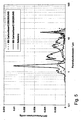
- FIG. 5 shows the pore spectra for one reference electrode (black, solid) and two electrodes with pore formers, one with the carbon fiber C10M250UNS (gray) and the other with the carbon fiber C25M350UNS (black, dashed).
- the pore-forming cathodes were prepared by the above-described recipe. All three cathodes were measured in the burned-out state, ie after residue-free combustion of the carbon fibers. It it becomes clear that in the reference cathode, pores with a diameter of 1 ⁇ m to 3 ⁇ m are mainly present.
- FIG. 6 shows the impedance spectrum (Nyquist plot) of a pore-forming cathode (circles or diamond symbols) and a reference cathode (gray triangles) in a half-cell measurement, as for FIG. 3 already described.
- the pore former cathode was filled with different amounts of electrolyte from 0.32 to 0.52 x the nickel coverage.
- the reference cathode was filled with a standard electrolyte amount of 0.42 ⁇ the nickel deposition amount.
- the impedance spectra were obtained in measurements in a cathode half cell test stand (see description of FIG. 3 ). In each case two identical cathodes were used per half-cell test (once as a working cathode and once as a counterelectrode).
Landscapes
- Chemical & Material Sciences (AREA)
- General Chemical & Material Sciences (AREA)
- Chemical Kinetics & Catalysis (AREA)
- Electrochemistry (AREA)
- Engineering & Computer Science (AREA)
- Ceramic Engineering (AREA)
- Materials Engineering (AREA)
- Manufacturing & Machinery (AREA)
- Structural Engineering (AREA)
- Organic Chemistry (AREA)
- Life Sciences & Earth Sciences (AREA)
- Sustainable Development (AREA)
- Sustainable Energy (AREA)
- Inert Electrodes (AREA)
- Fuel Cell (AREA)
Claims (16)
- Procédé de fabrication d'une électrode pour une pile à combustible à carbonate fondu, un mélange étant fabriqué pour la fabrication d'une couche d'électrode (10, 20) active électrochimiquement, ledit mélange contenant au moins un matériau d'électrode constitué de premières particules (11), au moins un matériau de formation de pores et au moins un liant, et l'ébauche crue résultante étant chauffée de manière à ce que le ou les matériaux de formation de pores et le ou les liants soient brûlés,
caractérisé en ce qu'au moins un matériau de formation d'images sous la forme de secondes particules (13, 23) ou sous la forme d'un matériau formant des secondes particules (13, 23) lors du séchage ou du chauffage du mélange est également introduit dans le mélange avant la combustion, en ce que les secondes particules (13, 23) sont plus petites que les premières particules (11) et plus petites que les particules du matériau de formation de pores dans l'ébauche crue, en ce que les secondes particules (13, 23) sont introduites en une quantité telle et en une taille telle que le matériau de formation d'images (13, 23) recouvre au moins en grande partie le matériau de formation de pores, et en ce qu'après la combustion du matériau de formation d'images, des cavités définies (12, 22) demeurent. - Procédé selon la revendication 1, caractérisé en ce que l'ébauche crue est appliquée sur un substrat d'électrode avant le chauffage et une mousse métallique, de préférence une mousse de nickel, est utilisée en tant que substrat d'électrode.
- Procédé selon la revendication 1 ou 2, caractérisé en ce que des substances qui brûlent sans résidu au plus à des températures de 600 °C à 650 °C sont utilisées en tant que matériau de formation de pores.
- Procédé selon l'une quelconque des revendications 1 à 3, caractérisé en ce que des fibres ramifiées ou non ramifiées, qui présentent un diamètre de 5 µm à 50 µm, de préférence de 5 µ à 20 µm, et/ou une longueur de 10 µm à 500 µm, de préférence de 100 µm à 200 µm, sont choisies en tant que matériau de formation de pores.
- Procédé selon l'une quelconque des revendications 1 à 3, caractérisé en ce que des particules d'une forme sphérique ou irrégulière, qui présentent un diamètre de 1 µm à 5 µm, de préférence de 3 µm, sont choisies en tant que matériau de formation de pores.
- Procédé selon l'une quelconque des revendications 1 à 5, caractérisé en ce que des particules d'une forme sphérique, cubique ou irrégulière, qui présentent notamment un diamètre inférieur ou égal à 3 µm, de préférence inférieur à 1 µm, sont choisies en tant que matériau de formation d'images.
- Procédé selon l'une quelconque des revendications 1 à 6, caractérisé en ce que les premières particules (11) ont une taille de 10 µm à 40 µm.
- Procédé selon l'une quelconque des revendications 1 à 7, caractérisé en ce que des poudres métalliques, des poudres d'oxydes métalliques, des hydrates d'oxydes métalliques, des sels métalliques inorganiques ou organiques sont utilisés en tant que matériau de formation d'images.
- Procédé selon la revendication 8, caractérisé en ce que des composés de nickel pyrolysables sont utilisés en tant que matériau de formation d'images.
- Procédé selon la revendication 9, caractérisé en ce que des sels de nickel pyrolysables sont utilisés, de préférence du nitrate de nickel ou de l'acétate de nickel.
- Procédé selon la revendication 10, caractérisé en ce que les sels de nickel sont formés in situ par ajout d'un acide, de préférence d'acide acétique ou d'acide nitrique, au mélange contenant du nickel.
- Procédé selon la revendication 8, caractérisé en ce qu'une poudre d'oxyde métallique fine ou ultrafine, notamment une poudre d'oxyde de nickel, est utilisée.
- Procédé selon l'une quelconque des revendications 1 à 12, caractérisé en ce que le matériau de formation d'images est ajouté en une proportion de 3 % en poids à 15 % en poids, par rapport à la quantité totale du mélange.
- Procédé selon l'une quelconque des revendications 1 à 13, caractérisé en ce que le matériau de formation de pores et le matériau de formation d'images sont tout d'abord mélangés l'un avec l'autre, puis travaillés avec le ou les matériaux d'électrode et le ou les liants pour former le mélange.
- Procédé selon l'une quelconque des revendications 1 à 14, caractérisé en ce que le mélange est fabriqué sous la forme d'une pâte d'électrode ou à partir d'un mélange pulvérulent.
- Procédé selon l'une quelconque des revendications 1 à 15, caractérisé en ce que le mélange est fabriqué sous la forme d'un système aqueux ou alcoolique.
Applications Claiming Priority (3)
| Application Number | Priority Date | Filing Date | Title |
|---|---|---|---|
| DE102006036849 | 2006-08-07 | ||
| DE102006047823A DE102006047823A1 (de) | 2006-08-07 | 2006-10-10 | Elektrode für eine Schmelzkarbonat-Brennstollzelle und Verfahren zu ihrer Herstellung |
| PCT/EP2007/006804 WO2008017409A1 (fr) | 2006-08-07 | 2007-08-01 | Électrode pour une pile à combustible à carbonate fondu et son procédé de fabrication |
Publications (2)
| Publication Number | Publication Date |
|---|---|
| EP2050155A1 EP2050155A1 (fr) | 2009-04-22 |
| EP2050155B1 true EP2050155B1 (fr) | 2010-12-22 |
Family
ID=38650003
Family Applications (1)
| Application Number | Title | Priority Date | Filing Date |
|---|---|---|---|
| EP07786491A Not-in-force EP2050155B1 (fr) | 2006-08-07 | 2007-08-01 | Électrode pour une pile à combustible à carbonate fondu et son procédé de fabrication |
Country Status (9)
| Country | Link |
|---|---|
| US (1) | US20110033771A1 (fr) |
| EP (1) | EP2050155B1 (fr) |
| JP (1) | JP5280358B2 (fr) |
| KR (1) | KR101392712B1 (fr) |
| CN (1) | CN101501901B (fr) |
| AT (1) | ATE492916T1 (fr) |
| CA (1) | CA2660214A1 (fr) |
| DE (2) | DE102006047823A1 (fr) |
| WO (1) | WO2008017409A1 (fr) |
Families Citing this family (16)
| Publication number | Priority date | Publication date | Assignee | Title |
|---|---|---|---|---|
| DE102009050435A1 (de) | 2009-08-13 | 2011-02-17 | Mtu Onsite Energy Gmbh | Elektrode für eine Schmelzkarbonat-Brennstoffzelle und Verfahren zu ihrer Herstellung |
| KR101298622B1 (ko) * | 2010-05-06 | 2013-08-26 | 두산중공업 주식회사 | 연료전지용 전극체 |
| DE102017206693A1 (de) * | 2017-04-20 | 2018-10-25 | Robert Bosch Gmbh | Verfahren zur Herstellung einer Funktionsschicht |
| DE102018207773A1 (de) * | 2018-05-17 | 2019-11-21 | Robert Bosch Gmbh | Verfahren zur Herstellung poröser Elektroden für elektrochemische Zellen |
| WO2020112774A1 (fr) | 2018-11-30 | 2020-06-04 | Exxonmobil Research And Engineering Company | Fonctionnement à pression élevée de piles à combustible à carbonate fondu doué d'une utilisation de co2 améliorée |
| WO2020112804A1 (fr) | 2018-11-30 | 2020-06-04 | Exxonmobil Research And Engineering Company | Structures de collecteur de cathode pour pile à combustible à carbonate fondu |
| WO2020112806A1 (fr) * | 2018-11-30 | 2020-06-04 | Exxonmobil Research And Engineering Company | Cathode en couches pour pile à combustible à carbonate fondu |
| WO2020112770A1 (fr) | 2018-11-30 | 2020-06-04 | Exxonmobil Research And Engineering Company | Régénération de piles à combustible à carbonate fondu destinée à la capture profonde de co2 |
| CA3121538C (fr) | 2018-11-30 | 2023-09-12 | Exxonmobile Research And Engineering Company | Methode de production d'electricite dans une pile a combustible a carbonate fondu |
| US11888187B2 (en) | 2018-11-30 | 2024-01-30 | ExxonMobil Technology and Engineering Company | Operation of molten carbonate fuel cells with enhanced CO2 utilization |
| KR102610184B1 (ko) | 2018-11-30 | 2023-12-04 | 퓨얼셀 에너지, 인크 | 용융 탄산염 연료 전지를 위한 연료 전지 스테이징 |
| US11742508B2 (en) | 2018-11-30 | 2023-08-29 | ExxonMobil Technology and Engineering Company | Reforming catalyst pattern for fuel cell operated with enhanced CO2 utilization |
| JP2023503995A (ja) | 2019-11-26 | 2023-02-01 | エクソンモービル・テクノロジー・アンド・エンジニアリング・カンパニー | 燃料電池モジュールのアセンブリおよびそれを使用するシステム |
| JP7515584B2 (ja) | 2019-11-26 | 2024-07-12 | エクソンモービル テクノロジー アンド エンジニアリング カンパニー | 高電解質充填レベルでの溶融炭酸塩型燃料電池の作動 |
| CN114930589B (zh) | 2019-11-26 | 2025-05-30 | 埃克森美孚技术与工程公司 | 具有用于平行流动的外部歧管的燃料电池组件 |
| US11978931B2 (en) | 2021-02-11 | 2024-05-07 | ExxonMobil Technology and Engineering Company | Flow baffle for molten carbonate fuel cell |
Family Cites Families (14)
| Publication number | Priority date | Publication date | Assignee | Title |
|---|---|---|---|---|
| GB963767A (en) * | 1961-05-18 | 1964-07-15 | Leesona Corp | Improvements in or relating to fuel cells |
| US4058482A (en) * | 1976-12-20 | 1977-11-15 | United Technologies Corporation | Fuel cell electrode |
| US4708917A (en) * | 1985-12-23 | 1987-11-24 | International Fuel Cells Corporation | Molten carbonate cathodes and method of fabricating |
| JPS62154576A (ja) * | 1985-12-27 | 1987-07-09 | Fuji Electric Corp Res & Dev Ltd | 溶融炭酸塩燃料電池の製造方法 |
| JPS6324558A (ja) * | 1986-07-16 | 1988-02-01 | Hitachi Zosen Corp | 溶融炭酸塩型燃料電池用電極の製造方法 |
| US4780437A (en) * | 1987-02-11 | 1988-10-25 | The United States Of America As Represented By The United States Department Of Energy | Fabrication of catalytic electrodes for molten carbonate fuel cells |
| JPS6452382A (en) * | 1987-08-22 | 1989-02-28 | Fuji Electric Co Ltd | Manufacture of electrode for molten carbonate fuel cell |
| IT1241857B (it) * | 1990-06-01 | 1994-02-01 | Ansaldo Spa | Procedimento per la fabbricazione di catodi per celle a carbonati fusi |
| JPH07118327B2 (ja) * | 1990-07-07 | 1995-12-18 | 日本碍子株式会社 | 固体電解質型燃料電池及びこれに用いる多孔質電極体 |
| DE4303136C1 (de) * | 1993-02-04 | 1994-06-16 | Mtu Friedrichshafen Gmbh | Verfahren zur Herstellung von Schmelzcarbonat-Brennstoffzellen |
| JPH06290787A (ja) * | 1993-03-31 | 1994-10-18 | Youyuu Tansanengata Nenryo Denchi Hatsuden Syst Gijutsu Kenkyu Kumiai | 溶融炭酸塩型燃料電池空気極用前駆グリーンシート |
| KR0123709B1 (ko) * | 1994-08-17 | 1997-12-09 | 김광호 | 용융탄산염 연료전지용 양전극 및 그 제조방법 |
| JP3206904B2 (ja) * | 1999-09-22 | 2001-09-10 | 溶融炭酸塩型燃料電池発電システム技術研究組合 | 燃料電池の電極製造方法 |
| WO2004035466A1 (fr) * | 2002-10-18 | 2004-04-29 | Monsanto Technology Llc | Catalyseur au cuivre a support metallique pour reformage des alcools |
-
2006
- 2006-10-10 DE DE102006047823A patent/DE102006047823A1/de not_active Withdrawn
-
2007
- 2007-08-01 US US12/376,357 patent/US20110033771A1/en not_active Abandoned
- 2007-08-01 DE DE502007006043T patent/DE502007006043D1/de active Active
- 2007-08-01 WO PCT/EP2007/006804 patent/WO2008017409A1/fr not_active Ceased
- 2007-08-01 CN CN200780029221XA patent/CN101501901B/zh not_active Expired - Fee Related
- 2007-08-01 CA CA002660214A patent/CA2660214A1/fr not_active Abandoned
- 2007-08-01 JP JP2009523179A patent/JP5280358B2/ja not_active Expired - Fee Related
- 2007-08-01 EP EP07786491A patent/EP2050155B1/fr not_active Not-in-force
- 2007-08-01 AT AT07786491T patent/ATE492916T1/de active
- 2007-08-01 KR KR1020097004757A patent/KR101392712B1/ko not_active Expired - Fee Related
Also Published As
| Publication number | Publication date |
|---|---|
| DE502007006043D1 (de) | 2011-02-03 |
| ATE492916T1 (de) | 2011-01-15 |
| KR20090064373A (ko) | 2009-06-18 |
| CA2660214A1 (fr) | 2008-02-14 |
| DE102006047823A1 (de) | 2008-02-14 |
| JP2010500705A (ja) | 2010-01-07 |
| KR101392712B1 (ko) | 2014-05-12 |
| CN101501901A (zh) | 2009-08-05 |
| US20110033771A1 (en) | 2011-02-10 |
| WO2008017409A1 (fr) | 2008-02-14 |
| JP5280358B2 (ja) | 2013-09-04 |
| CN101501901B (zh) | 2011-07-06 |
| EP2050155A1 (fr) | 2009-04-22 |
Similar Documents
| Publication | Publication Date | Title |
|---|---|---|
| EP2050155B1 (fr) | Électrode pour une pile à combustible à carbonate fondu et son procédé de fabrication | |
| EP1343215B1 (fr) | Corps structuré utilisé comme anode pour une cellule à combustible | |
| EP2759009B1 (fr) | Couche de diffusion de gaz avec une conductibilité électrique améliorée et perméabilité au gaz | |
| DE2720529C2 (de) | Verfahren zur Herstellung einer Brennstoffzellenelektrode | |
| EP1118129B1 (fr) | Electrode a diffusion gazeuse et procede de sa production | |
| DE19963882A1 (de) | Elektrode für Hochtemperatur-Brennstoffzelle und Verfahren zur Herstellung derselben | |
| EP0797265A2 (fr) | Electrode à diffusion gazeuse pour piles à combustible à membrane et méthode de fabrication | |
| DE112006000220T5 (de) | Zelle für Festoxid-Brennstoffzelle und Verfahren zur Herstellung einer Zelle für Festoxid-Brennstoffzelle | |
| DE102010028242A1 (de) | Elektrode für eine Polymer-Elektrolyt-Membran-Brennstoffzelle und Verfahren zum Bilden einer Membran-Elektroden-Anordnung unter Verwendung derselben | |
| EP1150369A1 (fr) | Structures de distributeurs de gaz et électrodes à diffusion gazeuze pour des piles à combustible | |
| EP1246288B1 (fr) | Sous-couche poreuse perméable aux gaz d'une couche mince imperméable aux gaz, servant de composant fonctionnel dans les piles à combustible fonctionnant à haute température | |
| EP1295353B1 (fr) | Procede pour produire une electrode a conductivite a constance thermique | |
| EP0645832B1 (fr) | Electrode négative pour accumulateurs alcalins étanches ou gaz pourvue une couche contenant de noir de carbone pour la consommation des gaz | |
| DE102007000325A1 (de) | Verfahren für das Herstellen eines Keramik-Stapels | |
| DE3238824A1 (de) | Sauerstoffmessfuehlerelement und verfahren zu dessen herstellung | |
| DE69110581T2 (de) | Verfahren zur Herstellung von Kathoden für Zellen mit geschmolzenen Karbonat-Elektrolyten. | |
| WO2010037665A1 (fr) | Cellule électrochimique haute température et dispositif de cellules électrochimiques correspondant | |
| DE19935271C2 (de) | Matrixmaterial für Brennstoffzellen sowie Verfahren zu seiner Herstellung und seine Verwendung | |
| EP4198175A2 (fr) | Électrolyte supporté, son procédé de fabrication et son utilisation | |
| DE102011083538A1 (de) | Speicherelement für eine Festelektrolyt-Batterie sowie Verfahren zu dessen Herstellung | |
| DE102007060272A1 (de) | Bipolarplatte und Verfahren zum Herstellen einer Schutzschicht an einer Bipolarplatte | |
| DE10212966B4 (de) | Hochtemperatur-Brennstoffzelle und Verfahren zu deren Herstellung | |
| EP3903373B1 (fr) | Procédé de fabrication d'une couche fonctionnelle en céramique | |
| DE112020001817T5 (de) | Festoxid-Brennstoffzelle, umfassend eine mit alkalibasiertem Promotor beladene Anode | |
| EP2465159A2 (fr) | Électrode pour une pile à combustible à carbonate fondu et son procédé de fabrication |
Legal Events
| Date | Code | Title | Description |
|---|---|---|---|
| PUAI | Public reference made under article 153(3) epc to a published international application that has entered the european phase |
Free format text: ORIGINAL CODE: 0009012 |
|
| 17P | Request for examination filed |
Effective date: 20090209 |
|
| AK | Designated contracting states |
Kind code of ref document: A1 Designated state(s): AT BE BG CH CY CZ DE DK EE ES FI FR GB GR HU IE IS IT LI LT LU LV MC MT NL PL PT RO SE SI SK TR |
|
| AX | Request for extension of the european patent |
Extension state: AL BA HR MK RS |
|
| 17Q | First examination report despatched |
Effective date: 20090511 |
|
| GRAP | Despatch of communication of intention to grant a patent |
Free format text: ORIGINAL CODE: EPIDOSNIGR1 |
|
| GRAS | Grant fee paid |
Free format text: ORIGINAL CODE: EPIDOSNIGR3 |
|
| GRAA | (expected) grant |
Free format text: ORIGINAL CODE: 0009210 |
|
| AK | Designated contracting states |
Kind code of ref document: B1 Designated state(s): AT BE BG CH CY CZ DE DK EE ES FI FR GB GR HU IE IS IT LI LT LU LV MC MT NL PL PT RO SE SI SK TR |
|
| REG | Reference to a national code |
Ref country code: GB Ref legal event code: FG4D Free format text: NOT ENGLISH |
|
| REG | Reference to a national code |
Ref country code: CH Ref legal event code: EP |
|
| REG | Reference to a national code |
Ref country code: IE Ref legal event code: FG4D |
|
| REF | Corresponds to: |
Ref document number: 502007006043 Country of ref document: DE Date of ref document: 20110203 Kind code of ref document: P |
|
| REG | Reference to a national code |
Ref country code: DE Ref legal event code: R096 Ref document number: 502007006043 Country of ref document: DE Effective date: 20110203 |
|
| REG | Reference to a national code |
Ref country code: NL Ref legal event code: T3 |
|
| REG | Reference to a national code |
Ref country code: ES Ref legal event code: FG2A Ref document number: 2356460 Country of ref document: ES Kind code of ref document: T3 Effective date: 20110408 |
|
| PG25 | Lapsed in a contracting state [announced via postgrant information from national office to epo] |
Ref country code: LT Free format text: LAPSE BECAUSE OF FAILURE TO SUBMIT A TRANSLATION OF THE DESCRIPTION OR TO PAY THE FEE WITHIN THE PRESCRIBED TIME-LIMIT Effective date: 20101222 |
|
| LTIE | Lt: invalidation of european patent or patent extension |
Effective date: 20101222 |
|
| PG25 | Lapsed in a contracting state [announced via postgrant information from national office to epo] |
Ref country code: SI Free format text: LAPSE BECAUSE OF FAILURE TO SUBMIT A TRANSLATION OF THE DESCRIPTION OR TO PAY THE FEE WITHIN THE PRESCRIBED TIME-LIMIT Effective date: 20101222 Ref country code: FI Free format text: LAPSE BECAUSE OF FAILURE TO SUBMIT A TRANSLATION OF THE DESCRIPTION OR TO PAY THE FEE WITHIN THE PRESCRIBED TIME-LIMIT Effective date: 20101222 Ref country code: LV Free format text: LAPSE BECAUSE OF FAILURE TO SUBMIT A TRANSLATION OF THE DESCRIPTION OR TO PAY THE FEE WITHIN THE PRESCRIBED TIME-LIMIT Effective date: 20101222 Ref country code: BG Free format text: LAPSE BECAUSE OF FAILURE TO SUBMIT A TRANSLATION OF THE DESCRIPTION OR TO PAY THE FEE WITHIN THE PRESCRIBED TIME-LIMIT Effective date: 20110322 Ref country code: CY Free format text: LAPSE BECAUSE OF FAILURE TO SUBMIT A TRANSLATION OF THE DESCRIPTION OR TO PAY THE FEE WITHIN THE PRESCRIBED TIME-LIMIT Effective date: 20101222 Ref country code: SE Free format text: LAPSE BECAUSE OF FAILURE TO SUBMIT A TRANSLATION OF THE DESCRIPTION OR TO PAY THE FEE WITHIN THE PRESCRIBED TIME-LIMIT Effective date: 20101222 |
|
| REG | Reference to a national code |
Ref country code: IE Ref legal event code: FD4D |
|
| PG25 | Lapsed in a contracting state [announced via postgrant information from national office to epo] |
Ref country code: PT Free format text: LAPSE BECAUSE OF FAILURE TO SUBMIT A TRANSLATION OF THE DESCRIPTION OR TO PAY THE FEE WITHIN THE PRESCRIBED TIME-LIMIT Effective date: 20110422 Ref country code: CZ Free format text: LAPSE BECAUSE OF FAILURE TO SUBMIT A TRANSLATION OF THE DESCRIPTION OR TO PAY THE FEE WITHIN THE PRESCRIBED TIME-LIMIT Effective date: 20101222 Ref country code: EE Free format text: LAPSE BECAUSE OF FAILURE TO SUBMIT A TRANSLATION OF THE DESCRIPTION OR TO PAY THE FEE WITHIN THE PRESCRIBED TIME-LIMIT Effective date: 20101222 Ref country code: GR Free format text: LAPSE BECAUSE OF FAILURE TO SUBMIT A TRANSLATION OF THE DESCRIPTION OR TO PAY THE FEE WITHIN THE PRESCRIBED TIME-LIMIT Effective date: 20110323 Ref country code: IS Free format text: LAPSE BECAUSE OF FAILURE TO SUBMIT A TRANSLATION OF THE DESCRIPTION OR TO PAY THE FEE WITHIN THE PRESCRIBED TIME-LIMIT Effective date: 20110422 |
|
| PG25 | Lapsed in a contracting state [announced via postgrant information from national office to epo] |
Ref country code: RO Free format text: LAPSE BECAUSE OF FAILURE TO SUBMIT A TRANSLATION OF THE DESCRIPTION OR TO PAY THE FEE WITHIN THE PRESCRIBED TIME-LIMIT Effective date: 20101222 Ref country code: PL Free format text: LAPSE BECAUSE OF FAILURE TO SUBMIT A TRANSLATION OF THE DESCRIPTION OR TO PAY THE FEE WITHIN THE PRESCRIBED TIME-LIMIT Effective date: 20101222 Ref country code: SK Free format text: LAPSE BECAUSE OF FAILURE TO SUBMIT A TRANSLATION OF THE DESCRIPTION OR TO PAY THE FEE WITHIN THE PRESCRIBED TIME-LIMIT Effective date: 20101222 |
|
| PLBE | No opposition filed within time limit |
Free format text: ORIGINAL CODE: 0009261 |
|
| STAA | Information on the status of an ep patent application or granted ep patent |
Free format text: STATUS: NO OPPOSITION FILED WITHIN TIME LIMIT |
|
| PG25 | Lapsed in a contracting state [announced via postgrant information from national office to epo] |
Ref country code: IE Free format text: LAPSE BECAUSE OF FAILURE TO SUBMIT A TRANSLATION OF THE DESCRIPTION OR TO PAY THE FEE WITHIN THE PRESCRIBED TIME-LIMIT Effective date: 20101222 Ref country code: DK Free format text: LAPSE BECAUSE OF FAILURE TO SUBMIT A TRANSLATION OF THE DESCRIPTION OR TO PAY THE FEE WITHIN THE PRESCRIBED TIME-LIMIT Effective date: 20101222 |
|
| PGFP | Annual fee paid to national office [announced via postgrant information from national office to epo] |
Ref country code: CH Payment date: 20110824 Year of fee payment: 5 |
|
| 26N | No opposition filed |
Effective date: 20110923 |
|
| PG25 | Lapsed in a contracting state [announced via postgrant information from national office to epo] |
Ref country code: MT Free format text: LAPSE BECAUSE OF FAILURE TO SUBMIT A TRANSLATION OF THE DESCRIPTION OR TO PAY THE FEE WITHIN THE PRESCRIBED TIME-LIMIT Effective date: 20101222 |
|
| REG | Reference to a national code |
Ref country code: DE Ref legal event code: R097 Ref document number: 502007006043 Country of ref document: DE Effective date: 20110923 |
|
| BERE | Be: lapsed |
Owner name: MTU ONSITE ENERGY G.M.B.H. Effective date: 20110831 |
|
| PG25 | Lapsed in a contracting state [announced via postgrant information from national office to epo] |
Ref country code: MC Free format text: LAPSE BECAUSE OF NON-PAYMENT OF DUE FEES Effective date: 20110831 |
|
| PG25 | Lapsed in a contracting state [announced via postgrant information from national office to epo] |
Ref country code: BE Free format text: LAPSE BECAUSE OF NON-PAYMENT OF DUE FEES Effective date: 20110831 |
|
| PGFP | Annual fee paid to national office [announced via postgrant information from national office to epo] |
Ref country code: GB Payment date: 20120821 Year of fee payment: 6 |
|
| PGFP | Annual fee paid to national office [announced via postgrant information from national office to epo] |
Ref country code: ES Payment date: 20120828 Year of fee payment: 6 Ref country code: IT Payment date: 20120821 Year of fee payment: 6 Ref country code: FR Payment date: 20120906 Year of fee payment: 6 |
|
| PGFP | Annual fee paid to national office [announced via postgrant information from national office to epo] |
Ref country code: NL Payment date: 20120821 Year of fee payment: 6 |
|
| REG | Reference to a national code |
Ref country code: DE Ref legal event code: R081 Ref document number: 502007006043 Country of ref document: DE Owner name: FRAUNHOFER-GESELLSCHAFT ZUR FOERDERUNG DER ANG, DE Free format text: FORMER OWNER: MTU FRIEDRICHSHAFEN GMBH, 88045 FRIEDRICHSHAFEN, DE Effective date: 20130514 Ref country code: DE Ref legal event code: R081 Ref document number: 502007006043 Country of ref document: DE Owner name: FRAUNHOFER-GESELLSCHAFT ZUR FOERDERUNG DER ANG, DE Free format text: FORMER OWNER: MTU ONSITE ENERGY GMBH, 85521 OTTOBRUNN, DE Effective date: 20130408 |
|
| PG25 | Lapsed in a contracting state [announced via postgrant information from national office to epo] |
Ref country code: LU Free format text: LAPSE BECAUSE OF NON-PAYMENT OF DUE FEES Effective date: 20110801 |
|
| PG25 | Lapsed in a contracting state [announced via postgrant information from national office to epo] |
Ref country code: TR Free format text: LAPSE BECAUSE OF FAILURE TO SUBMIT A TRANSLATION OF THE DESCRIPTION OR TO PAY THE FEE WITHIN THE PRESCRIBED TIME-LIMIT Effective date: 20101222 |
|
| REG | Reference to a national code |
Ref country code: AT Ref legal event code: MM01 Ref document number: 492916 Country of ref document: AT Kind code of ref document: T Effective date: 20120831 |
|
| PG25 | Lapsed in a contracting state [announced via postgrant information from national office to epo] |
Ref country code: HU Free format text: LAPSE BECAUSE OF FAILURE TO SUBMIT A TRANSLATION OF THE DESCRIPTION OR TO PAY THE FEE WITHIN THE PRESCRIBED TIME-LIMIT Effective date: 20101222 Ref country code: AT Free format text: LAPSE BECAUSE OF NON-PAYMENT OF DUE FEES Effective date: 20120831 |
|
| REG | Reference to a national code |
Ref country code: NL Ref legal event code: V1 Effective date: 20140301 |
|
| REG | Reference to a national code |
Ref country code: CH Ref legal event code: PL |
|
| GBPC | Gb: european patent ceased through non-payment of renewal fee |
Effective date: 20130801 |
|
| PG25 | Lapsed in a contracting state [announced via postgrant information from national office to epo] |
Ref country code: LI Free format text: LAPSE BECAUSE OF NON-PAYMENT OF DUE FEES Effective date: 20130831 Ref country code: NL Free format text: LAPSE BECAUSE OF NON-PAYMENT OF DUE FEES Effective date: 20140301 Ref country code: CH Free format text: LAPSE BECAUSE OF NON-PAYMENT OF DUE FEES Effective date: 20130831 |
|
| REG | Reference to a national code |
Ref country code: FR Ref legal event code: ST Effective date: 20140430 |
|
| PG25 | Lapsed in a contracting state [announced via postgrant information from national office to epo] |
Ref country code: IT Free format text: LAPSE BECAUSE OF NON-PAYMENT OF DUE FEES Effective date: 20130801 |
|
| PG25 | Lapsed in a contracting state [announced via postgrant information from national office to epo] |
Ref country code: GB Free format text: LAPSE BECAUSE OF NON-PAYMENT OF DUE FEES Effective date: 20130801 |
|
| PG25 | Lapsed in a contracting state [announced via postgrant information from national office to epo] |
Ref country code: FR Free format text: LAPSE BECAUSE OF NON-PAYMENT OF DUE FEES Effective date: 20130902 |
|
| REG | Reference to a national code |
Ref country code: ES Ref legal event code: FD2A Effective date: 20140909 |
|
| PG25 | Lapsed in a contracting state [announced via postgrant information from national office to epo] |
Ref country code: ES Free format text: LAPSE BECAUSE OF NON-PAYMENT OF DUE FEES Effective date: 20130802 |
|
| PGFP | Annual fee paid to national office [announced via postgrant information from national office to epo] |
Ref country code: DE Payment date: 20220822 Year of fee payment: 16 |
|
| P01 | Opt-out of the competence of the unified patent court (upc) registered |
Effective date: 20230524 |
|
| REG | Reference to a national code |
Ref country code: DE Ref legal event code: R119 Ref document number: 502007006043 Country of ref document: DE |
|
| PG25 | Lapsed in a contracting state [announced via postgrant information from national office to epo] |
Ref country code: DE Free format text: LAPSE BECAUSE OF NON-PAYMENT OF DUE FEES Effective date: 20240301 |