EP2050509A1 - Spender zum giessen von viskosem material - Google Patents
Spender zum giessen von viskosem material Download PDFInfo
- Publication number
- EP2050509A1 EP2050509A1 EP07767531A EP07767531A EP2050509A1 EP 2050509 A1 EP2050509 A1 EP 2050509A1 EP 07767531 A EP07767531 A EP 07767531A EP 07767531 A EP07767531 A EP 07767531A EP 2050509 A1 EP2050509 A1 EP 2050509A1
- Authority
- EP
- European Patent Office
- Prior art keywords
- plunger
- syringe body
- dispenser
- contents
- extruding
- Prior art date
- Legal status (The legal status is an assumption and is not a legal conclusion. Google has not performed a legal analysis and makes no representation as to the accuracy of the status listed.)
- Granted
Links
Images




Classifications
-
- B—PERFORMING OPERATIONS; TRANSPORTING
- B05—SPRAYING OR ATOMISING IN GENERAL; APPLYING FLUENT MATERIALS TO SURFACES, IN GENERAL
- B05C—APPARATUS FOR APPLYING FLUENT MATERIALS TO SURFACES, IN GENERAL
- B05C5/00—Apparatus in which liquid or other fluent material is projected, poured or allowed to flow on to the surface of the work
-
- A—HUMAN NECESSITIES
- A61—MEDICAL OR VETERINARY SCIENCE; HYGIENE
- A61C—DENTISTRY; APPARATUS OR METHODS FOR ORAL OR DENTAL HYGIENE
- A61C5/00—Filling or capping teeth
- A61C5/60—Devices specially adapted for pressing or mixing capping or filling materials, e.g. amalgam presses
- A61C5/62—Applicators, e.g. syringes or guns
-
- B—PERFORMING OPERATIONS; TRANSPORTING
- B05—SPRAYING OR ATOMISING IN GENERAL; APPLYING FLUENT MATERIALS TO SURFACES, IN GENERAL
- B05C—APPARATUS FOR APPLYING FLUENT MATERIALS TO SURFACES, IN GENERAL
- B05C17/00—Hand tools or apparatus using hand held tools, for applying liquids or other fluent materials to, for spreading applied liquids or other fluent materials on, or for partially removing applied liquids or other fluent materials from, surfaces
- B05C17/005—Hand tools or apparatus using hand held tools, for applying liquids or other fluent materials to, for spreading applied liquids or other fluent materials on, or for partially removing applied liquids or other fluent materials from, surfaces for discharging material from a reservoir or container located in or on the hand tool through an outlet orifice by pressure without using surface contacting members like pads or brushes
-
- B—PERFORMING OPERATIONS; TRANSPORTING
- B05—SPRAYING OR ATOMISING IN GENERAL; APPLYING FLUENT MATERIALS TO SURFACES, IN GENERAL
- B05C—APPARATUS FOR APPLYING FLUENT MATERIALS TO SURFACES, IN GENERAL
- B05C17/00—Hand tools or apparatus using hand held tools, for applying liquids or other fluent materials to, for spreading applied liquids or other fluent materials on, or for partially removing applied liquids or other fluent materials from, surfaces
- B05C17/005—Hand tools or apparatus using hand held tools, for applying liquids or other fluent materials to, for spreading applied liquids or other fluent materials on, or for partially removing applied liquids or other fluent materials from, surfaces for discharging material from a reservoir or container located in or on the hand tool through an outlet orifice by pressure without using surface contacting members like pads or brushes
- B05C17/00576—Hand tools or apparatus using hand held tools, for applying liquids or other fluent materials to, for spreading applied liquids or other fluent materials on, or for partially removing applied liquids or other fluent materials from, surfaces for discharging material from a reservoir or container located in or on the hand tool through an outlet orifice by pressure without using surface contacting members like pads or brushes characterised by the construction of a piston as pressure exerting means, or of the co-operating container
Definitions
- the present invention relates to a dispenser suitable for extruding various composites and/or other viscous materials used for dental treatment or the like, and intends to certainly prevent drips of contents from the tip of a nozzle.
- a paste material with high viscosity such as composite or an adhesive is often used for dental treatment or the like.
- a syringe type dispenser is typically used to extrude contents from a small diameter nozzle by pressing a plunger.
- a plunger is operated to extrude contents filled therein usually in multiple stages (i.e. all contents are not extruded by a single operation), and the operation of the plunger is interrupted so as to shut off the extrusion of the contents. But even after the interruption, the pressing force applied to the plunger remains as residual pressure in a filling space of contents, so that the contents leak out of the tip of the nozzle, which makes it difficult to extrude the appropriate amount of the contents and makes it impossible to utilize the expensive contents without waste.
- torsion of O-ring is caused in pressing operation of the plunger by imposing appropriate resistance to the O-ring, and the plunger is displaced backwardly by a restoring force of the O-ring exerted after the interruption of the extruding of the contents, thereby preventing drips of contents.
- the O-ring arranged in a groove may be moved to a position farthest from the nozzle side in the groove by the resistance between the O-ring and the container and thus the O-ring torsion, during pressing the plunger, cannot be caused to prevent drips of contents from the tip of the nozzle.
- An object of the invention is to propose a novel dispenser which can displace a plunger backward upon interrupting the extrusion of the contents and then certainly induce the accompanying suction effect (back suction) so as to prevent drips or leaks of contents.
- Another object of the invention is to propose a dispenser which can certainly discharge remaining air entrapped during filling of contents to prevent bubbles from mixing into the contents.
- the invention provides a dispenser comprising a syringe body having a space for filling contents and equipped with an extruding nozzle at its front end, a plunger slid, by pressing force applied thereto, in the syringe body to extrude the contents in the filling space from the tip of the extruding nozzle, an O-ring placed in an annular groove formed in the front end section of the plunger and slidable on the inner wall surface of the syringe body, wherein the annular groove is formed as a defined recess having a flat bottom wall over its entirety; a plurality of projections or grooves are formed on the sidewall of the annular groove with intervals therebetween so that the side portion of the O-ring comes into contact with the sidewall, being elastically displaced and then compressively deformed upon pressing the plunger while the O-ring is restored upon releasing the load applied for pressing the plunger to slide the plunger is slid in a direction opposed to the pressing direction, thus inducing back suction of
- the syringe body is provided with a polygonal flange on its outer wall.
- One or more ribs for discharging air with which the O-ring is in slidable contact are preferably provided on the front inner wall of the syringe body. It is more preferable that a step portion having a projection height smaller than the height of the rib is formed at the connecting portion between the rib and the inner wall of the syringe body. Furthermore, a projection or a rib can be formed on either one of the inner wall surface of the syringe body with which the front end of the plunger is in contact and the front end surface of the plunger, forming gaps between the inner wall of the syringe body and the front end of the plunger.
- the plunger is a hollow cylindrical with the front end being closed and that openings are formed in the peripheral wall at least at opposed positions.
- the O-ring comes into contact with a projection formed on the sidewall of the groove in the plunger and then embeds into the groove, being elastically displaced (the O-ring is displaced to wave shape in the adjacent area of the sidewall).
- the O-ring is compressively deformed so as to fill gaps between the sidewall of the groove and the O-ring deformed to wave shape.
- the O-ring When the pressing of the plunger is interrupted and thus the load applied thereto is released, the O-ring is to restore to its original shape while maintaining its position in the syringe body, causing the plunger to slide, according to the amount of elastic displacement and compressive deformation, to the direction opposed to the press-in direction. This depressurizes the filling space and thus induces back suction in which contents in the extruding nozzle are drawn into the filling space.
- the O-ring intrudes into gaps between projections or into grooves regardless of the depth of the grooves or the like, being elastically displaced and compressively deformed to wave shape over its entire circumference. Therefore, the back suction is certainly induced, thus preventing drips of contents from the tip of the nozzle.
- a polygonal flange can be provided on the outer wall of the syringe body, thereby preventing a dispenser from rolling when placed.
- One or more ribs for discharging air with which O-ring is in slidable contact are formed on the front inner wall of the syringe body.
- a projection or a rib can be formed on either one of the inner wall surface with which the front end of the plunger is in contact and the front end surface of the plunger, forming gaps between the inner wall of the syringe body and the front end of the plunger. Therefore, air remaining in dispenser during filling of the contents is certainly discharged through the gaps formed by the ribs, thus preventing bubbles from mixing into the contents.
- a step portion having a projection height smaller than the height of the rib is formed at the connecting portion between the rib and the inner wall of the syringe body, preventing the occurrence of scratch on the seal surface of a molded article when the molded article is removed from the mold in a molding step.
- the plunger is hollow cylindrical with its front end being closed and openings are formed in the peripheral wall at least at opposed positions.
- Such structure not only can prevent shrinkage in the groove in which O-ring is placed to stabilize the shape but also can hold a core through the openings from the cavity side to preclude offset of the core and thus prevent uneven thickness or defects of the plunger.
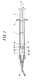
- FIG.1 shows a dispenser for filling a viscous material according to one preferred embodiment of the present invention
- FIG. 2 is an enlarged view of a main portion thereof.
- Reference numeral 1 in the drawings designates a cylindrical syringe body whose front and rear ends are open.
- the syringe body 1 has a space m for filling contents therein and an extruding nozzle 1a is equipped to the front end of the filling space.
- Reference numeral 2 designates a plunger slid in the syringe body 1 to extrude the contents in the filling space m from the tip of the extruding nozzle 1a.
- the plunger 2 is provided with a conical disc 2a and a pressing disc 2b at its front section, and an annular groove 2c having the width D is formed between the discs as a defined recess having a flat bottom wall over its entirety (see FIG.2 ).
- the conical disc 2a has a shape generally agree with the inner shape of the syringe body 1 so as to reduce the amount of the contents left after extruding out all contents in the syringe body 1, and is composed of a combination of a large-diameter disk portion 2a 1 and a small-diameter slender disk portion 2a 2 .
- Reference numeral 3 designates an O-ring placed in the groove 2c in the plunger 2 (when O-ring is set, there may be a gap in the groove 2c having the width D).
- the O-ring 3 is slidable on the inner wall surface of the syringe body 1 and seals the filling space m between the plunger 2 and the syringe body 1.
- the O-ring 3 has an elliptically-deformed shape due to contact with the inner wall of the syringe body 1 when the plunger 2 is set in the syringe body 1.
- a material for the O-ring 3 may be appropriately selected from silicone rubber, synthetic rubber, butyl rubber, fluoro rubber or the like. In view of resistance to contents, however, silicon rubber is preferable to be used to form the O-ring 3.
- Reference numeral 4 designates projections (or grooves) provided, at 90° intervals, on the sidewall of the pressing disc 2b of the plunger 2, as shown in the external perspective view of FIG.3 .
- the projections 4 causes the O-ring 3 to be elastically displaced to wave shape, by its contact with the side of the O-ring 3 during press-in operation of the plunger 2, at the adjacent area of the sidewall and then compressively deformed so as to fill the gaps between the sidewall of the groove and the O-ring 3 deformed to wave shape.
- the plunger 2 is slid to the direction A' opposed to the press-in direction A by the restoring force of the O-ring 3 exerted by releasing the load for pressing the plunger 2, thus inducing back suction (see FIG.1 ).
- reference numeral 5 designates a flange on which fingers are placed upon pressing the plunger 2.
- the O-ring 3 is in a state shown in FIG.2 before pressing the plunger 2, i.e. under an unloaded condition.
- the O-ring 3 comes into contact with the projections 4 thus being elastically displaced, and then partially intrudes into gaps between projections 4 thus being displaced to wave shape, as shown in FIG.4 .
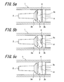
- the deformation states are schematically shown in FIGS. 5a, 5b and 5c .
- the O-ring 3 is initially in an elastically displaced state with a wave shape and eventually in a compressively deformed state shown in FIG.5c which is a state where the gaps between the sidewall of the groove and the O-ring 3 deformed, in the previous stage, to wave shape are filled. Thereafter, when the press-in of the plunger 2 is interrupted to release the load applied thereto, the elastically displaced O-ring 3 is to restore to its original shape while maintaining its position in the syringe body. The plunger 2 is slid in the direction opposed to the press-in direction by the restoring force thus caused and negative pressure is generated in the syringe body 1 to draw the contents in the extruding nozzle 1a into the filling space m.
- the projections 4 are provided as means for elastically displacing the O-ring 3, by way of example.
- This configuration is not particularly limited, and longitudinal ribs or grooves can be provided in place of the projections 4 to elastically displace the O-ring 3.
- the flange 5 can be adopted to have a polygonal shape to prevent a dispenser from rolling when the dispenser is placed.
- FIG.6 shows a dispenser for extruding a viscous material according to another preferred embodiment of the present invention.
- FIGS. 7-9 are enlarged views of a main portion of the dispenser.
- This embodiment illustrates the structure where four ribs 6 axially extending on the front inner wall of the syringe body 1 are circumferentially provided at even intervals (see FIG. 8 ).
- the rib 6 is arranged to be in slidable contact with the O-ring 3 in a state where the plunger 2 is at the side of the extruding nozzle 1a (i.e. a state where the plunger 2 is completely pressed-in in the syringe body 1).
- the ribs 6 at the open side of the syringe body 1 is arranged to be connected to the inner wall of the syringe body 1 via the step portion t (see FIG.7 ).
- the plunger 2 When contents are filled into the filling space m, the plunger 2 is located at the forefront of the syringe body 1 and the O-ring 3 is arranged to be in slidable contact with the rib 6.
- the extruding nozzle 1a is used to fill contents into the syringe body 1
- air in the syringe body 1 cannot be completely discharged during filling of contents and may be mixed into the contents as bubbles, making it difficult to extrude the precise amount of contents due to the bubble.
- the ribs 6 release the general state where the O-ring 3 and the inner wall of the syringe body 1 are sealed up by mutual contact, so that air in the syringe body 1 is discharged through gaps between ribs 6, preventing mixing of bubbles to the contents. Therefore, the above problem can be solved and thus the embodiment of the invention is considered preferable.
- a step portion t having a projection height smaller than the height of the rib 6 is formed at the connecting portion between the rib 6 and the inner wall surface of the syringe body 1, as shown in FIG.7 .
- the step portion t prevents the occurrence of scratch on the seal surface of the syringe body 1 when the syringe body I is removed from the mold in a molding step.
- the plunger 2 is a hollow cylindrical with its front end being closed and openings 7 can be provided in the peripheral wall at least at opposed positions.
- the contents may leak out from the rear part of the syringe body 1 due to instability of the shape of the sealed portion.
- the hollow cylindrical shape of the plunger 2 prevents the occurrence of shrinkage in molding or at the sealed portion of the annular groove 2c or the like in which O-ring 3 is placed, thus allowing the stable sealing.
- the openings 7 are also used to enable striking pins, which are distributed (or integrated) in a cavity upon molding the plunger 2, to abut on the core and thus hold the core from the cavity side, preventing offset of the core due to pressure in injection molding and thus precluding uneven thickness or defects of the molded plunger 2. Furthermore, the openings 7 serve as exhaust passages for remaining air entrapped during filling of contents.
- thermoplastic resin such as polyolefins, polyesters, polyethers or polystyrenes. More specifically polypropen (PP) or polyethylene (PE) as polyolefin material; polyethylene terephthalate (PET) or polybutylene terephthalate (PBT) as polyester material; polyoxymethylene (POM) as polyether material; AS or BS as polystyrene resin can be cited as typical examples. Any of these materials can be appropriately selected depending on applications or contents to be filled.
- the above resins can also be used to the extruding nozzle 1. Alternatively, the extruding nozzle 1a with its tip made of metal can be also used (see FIG.6 ).
- the invention provides an extruding dispenser in which an operation load of a plunger is stable and contents of the dispenser do not leak out.
- the invention provides an extruding dispenser certainly discharging remaining air entrapped in the dispenser during filling of contents to prevent mixing of bubbles to the contents and having excellent sealing capability to prevent leaks of contents.
Landscapes
- Health & Medical Sciences (AREA)
- Oral & Maxillofacial Surgery (AREA)
- Dentistry (AREA)
- Epidemiology (AREA)
- Life Sciences & Earth Sciences (AREA)
- Animal Behavior & Ethology (AREA)
- General Health & Medical Sciences (AREA)
- Public Health (AREA)
- Veterinary Medicine (AREA)
- Engineering & Computer Science (AREA)
- Mechanical Engineering (AREA)
- Dental Tools And Instruments Or Auxiliary Dental Instruments (AREA)
- Containers And Packaging Bodies Having A Special Means To Remove Contents (AREA)
- Coating Apparatus (AREA)
- Infusion, Injection, And Reservoir Apparatuses (AREA)
Applications Claiming Priority (2)
| Application Number | Priority Date | Filing Date | Title |
|---|---|---|---|
| JP2006192775A JP5133529B2 (ja) | 2006-07-13 | 2006-07-13 | 粘性材料の注出用ディスペンサー |
| PCT/JP2007/062725 WO2008007536A1 (fr) | 2006-07-13 | 2007-06-25 | Distributeur de matière visqueuse |
Publications (3)
| Publication Number | Publication Date |
|---|---|
| EP2050509A1 true EP2050509A1 (de) | 2009-04-22 |
| EP2050509A4 EP2050509A4 (de) | 2012-04-04 |
| EP2050509B1 EP2050509B1 (de) | 2016-05-04 |
Family
ID=38923101
Family Applications (1)
| Application Number | Title | Priority Date | Filing Date |
|---|---|---|---|
| EP07767531.2A Active EP2050509B1 (de) | 2006-07-13 | 2007-06-25 | Spender zum abgeben von viskosem material |
Country Status (8)
| Country | Link |
|---|---|
| US (1) | US8474656B2 (de) |
| EP (1) | EP2050509B1 (de) |
| JP (1) | JP5133529B2 (de) |
| KR (1) | KR101052488B1 (de) |
| CN (1) | CN101516526B (de) |
| AU (1) | AU2007273739B2 (de) |
| CA (1) | CA2657589C (de) |
| WO (1) | WO2008007536A1 (de) |
Cited By (4)
| Publication number | Priority date | Publication date | Assignee | Title |
|---|---|---|---|---|
| FR2982780A1 (fr) * | 2011-11-18 | 2013-05-24 | Buyer Ind De | Pistolet a pate culinaire |
| WO2013081297A1 (ko) * | 2011-11-28 | 2013-06-06 | 주식회사 허머 | 치과 기공용 왁스 디스펜서 및 이를 이용한 치과 기공용 왁스 디스펜서 시스템 |
| ITRE20120020A1 (it) * | 2012-03-14 | 2013-09-15 | Cgm Spa | Siringa per l'iniezione di materiale granulare solido |
| KR101358887B1 (ko) | 2011-11-28 | 2014-02-06 | 주식회사 허머 | 공기 주입식 치과 기공용 왁스 디스펜서 |
Families Citing this family (27)
| Publication number | Priority date | Publication date | Assignee | Title |
|---|---|---|---|---|
| JP5133529B2 (ja) * | 2006-07-13 | 2013-01-30 | クラレノリタケデンタル株式会社 | 粘性材料の注出用ディスペンサー |
| JP5362277B2 (ja) * | 2008-07-15 | 2013-12-11 | 株式会社ジーシー | シリンジ型容器 |
| JP5242469B2 (ja) * | 2009-03-19 | 2013-07-24 | 株式会社吉野工業所 | 粘性材料の注出用ディスペンサー |
| KR101066602B1 (ko) * | 2009-06-29 | 2011-09-22 | 에이피시스템 주식회사 | 액정 사출용 시린지 및 이를 이용한 액정 사출 장치와 액정 사출 방법 |
| JP5465936B2 (ja) | 2009-07-01 | 2014-04-09 | 武蔵エンジニアリング株式会社 | 液体材料吐出方法、装置およびプログラム |
| KR101107169B1 (ko) * | 2009-08-26 | 2012-01-25 | 삼성모바일디스플레이주식회사 | 수지 유체 디스펜싱 장치 |
| JP5285009B2 (ja) * | 2010-03-12 | 2013-09-11 | エムテックスマツムラ株式会社 | シーラガンにおける液だれ防止装置 |
| EP2561823B1 (de) * | 2010-04-22 | 2018-06-13 | Tokuyama Dental Corporation | Ausstossvorrichtung und verfahren zur füllung der ausstossvorrichtung mit einem füllmaterial |
| GB201009644D0 (en) * | 2010-06-09 | 2010-07-21 | Astek Innovations Ltd | Improved dental nozzle |
| US8616879B2 (en) * | 2011-03-22 | 2013-12-31 | Centrix, Inc. | Capsule and delivery tip with transition portion for dispensing viscous reactive dental materials |
| CN102178987A (zh) * | 2011-05-25 | 2011-09-14 | 杨桑 | 一种持续负压冲洗器 |
| CN102353620B (zh) * | 2011-06-21 | 2013-09-25 | 吉林大学 | 测定高温润湿性装置及方法 |
| CN104703559B (zh) * | 2012-05-25 | 2018-03-30 | 3M创新有限公司 | 用于分配牙科材料的施涂尖端和系统 |
| US9775685B2 (en) | 2012-09-28 | 2017-10-03 | Gc Corporation | Dental syringe |
| JP6382107B2 (ja) * | 2012-10-01 | 2018-09-05 | 武蔵エンジニアリング株式会社 | ディスペンサー用プランジャー、ディスペンサーおよび液体材料の吐出方法 |
| KR20150091076A (ko) | 2012-12-04 | 2015-08-07 | 술저 믹스팩 아게 | 분배 장치 |
| US20140263403A1 (en) * | 2013-03-15 | 2014-09-18 | Nordson Corporation | Liquid Dispensing Syringe |
| US9868653B2 (en) | 2013-05-01 | 2018-01-16 | Nch Corporation | System and method for treating water systems with high voltage discharge and ozone |
| CN103705311A (zh) * | 2014-01-21 | 2014-04-09 | 宋玮 | 一种牙科填补器 |
| CN105287026B (zh) * | 2015-11-26 | 2018-02-27 | 北京冠美口腔医院管理有限公司 | 一种凡士林提取器及其提取方法 |
| ITUA20162072A1 (it) | 2016-06-30 | 2017-12-30 | Platinum Corp Srl | Dropper a volume controllato |
| US20180207675A1 (en) * | 2016-10-29 | 2018-07-26 | Nh Real Estate Holdings Ltd. | Selective metered dose dispensing device |
| KR101801024B1 (ko) * | 2017-07-11 | 2017-11-24 | ㈜세일글로발 | 치과용 실린지 |
| DE102017130944A1 (de) * | 2017-12-21 | 2019-06-27 | Kulzer Gmbh | Nachlauffreie Spritze, insbesondere zur Verabreichung dentaler pastöser Zusammensetzungen |
| US11933401B2 (en) * | 2020-10-09 | 2024-03-19 | Enplas Corporation | Plunger, instrument, and mold |
| JP2024002735A (ja) * | 2022-06-24 | 2024-01-11 | 株式会社エンプラス | 筒状部材および器具 |
| KR102698010B1 (ko) * | 2024-01-19 | 2024-08-23 | (주)디엑스엠 | 잔압제거가 가능한 시린지 |
Family Cites Families (17)
| Publication number | Priority date | Publication date | Assignee | Title |
|---|---|---|---|---|
| US3976068A (en) * | 1975-01-03 | 1976-08-24 | Origo, Inc. | Drug dispenser for use with intravenous feeding pump |
| US4373535A (en) * | 1981-08-17 | 1983-02-15 | Martell Michael D | Venting, self-stopping, aspirating syringe |
| DK148467C (da) * | 1983-02-21 | 1985-12-16 | Radiometer As | Blodproevetagningsudstyr |
| US4852772A (en) * | 1987-12-07 | 1989-08-01 | Genesis Industries, Incorporated | Dispenser for viscous fluids |
| US4923096A (en) * | 1989-01-09 | 1990-05-08 | Mark L. Anderson | Dripless automatic syringe for dispensing fluids |
| JP3091516B2 (ja) * | 1991-05-23 | 2000-09-25 | アール ジョン.ジェー.ディスコ.ジェー | 歯科用シリンジ、およびそれとともに用いるカプセル |
| US5314416A (en) * | 1992-06-22 | 1994-05-24 | Sherwood Medical Company | Low friction syring assembly |
| DE19934841C1 (de) * | 1999-07-24 | 2001-03-01 | Vetter & Co Apotheker | Verfahren zur Beschichtung von Primärpackmitteln und Vorrichtung zur Durchführung des Verfahrens |
| JP2001057987A (ja) * | 1999-08-20 | 2001-03-06 | Gc Corp | 歯科用粘性材料用容器の押出し部構造 |
| JP4133071B2 (ja) * | 2001-08-20 | 2008-08-13 | 大成化工株式会社 | 後垂れ防止注入器、並びに、該注入器用プランジャ及びシール体 |
| WO2003033363A1 (en) * | 2001-10-16 | 2003-04-24 | Medical Instill Technologies, Inc. | Dispenser with sealed chamber and one-way valve for providing metered amounts of substances |
| CN2536887Y (zh) * | 2002-05-13 | 2003-02-19 | 武占龙 | 一种自动黄油枪 |
| CN2633316Y (zh) * | 2003-07-29 | 2004-08-18 | 上海米沙瓦医科工业有限公司 | 无菌双联混药器 |
| CN2726738Y (zh) * | 2004-06-11 | 2005-09-21 | 铁宝成 | 复用型植筋胶注射器 |
| JP4630079B2 (ja) * | 2005-01-28 | 2011-02-09 | 株式会社トクヤマ | ペースト注出器 |
| JP4759405B2 (ja) * | 2006-02-24 | 2011-08-31 | ニプロ株式会社 | プランジャ |
| JP5133529B2 (ja) * | 2006-07-13 | 2013-01-30 | クラレノリタケデンタル株式会社 | 粘性材料の注出用ディスペンサー |
-
2006
- 2006-07-13 JP JP2006192775A patent/JP5133529B2/ja active Active
-
2007
- 2007-06-25 EP EP07767531.2A patent/EP2050509B1/de active Active
- 2007-06-25 WO PCT/JP2007/062725 patent/WO2008007536A1/ja not_active Ceased
- 2007-06-25 US US12/309,108 patent/US8474656B2/en active Active
- 2007-06-25 KR KR1020097001970A patent/KR101052488B1/ko active Active
- 2007-06-25 AU AU2007273739A patent/AU2007273739B2/en active Active
- 2007-06-25 CA CA2657589A patent/CA2657589C/en active Active
- 2007-06-25 CN CN2007800331040A patent/CN101516526B/zh active Active
Cited By (6)
| Publication number | Priority date | Publication date | Assignee | Title |
|---|---|---|---|---|
| FR2982780A1 (fr) * | 2011-11-18 | 2013-05-24 | Buyer Ind De | Pistolet a pate culinaire |
| WO2013081297A1 (ko) * | 2011-11-28 | 2013-06-06 | 주식회사 허머 | 치과 기공용 왁스 디스펜서 및 이를 이용한 치과 기공용 왁스 디스펜서 시스템 |
| KR101358887B1 (ko) | 2011-11-28 | 2014-02-06 | 주식회사 허머 | 공기 주입식 치과 기공용 왁스 디스펜서 |
| ITRE20120020A1 (it) * | 2012-03-14 | 2013-09-15 | Cgm Spa | Siringa per l'iniezione di materiale granulare solido |
| WO2013136168A1 (en) * | 2012-03-14 | 2013-09-19 | C.G.M. S.P.A. | A syringe for injecting solid granular material |
| US9731078B2 (en) | 2012-03-14 | 2017-08-15 | C.G.M. S.P.A. | Syringe for injecting solid granular material |
Also Published As
| Publication number | Publication date |
|---|---|
| JP5133529B2 (ja) | 2013-01-30 |
| JP2008018351A (ja) | 2008-01-31 |
| KR20090046813A (ko) | 2009-05-11 |
| CN101516526A (zh) | 2009-08-26 |
| AU2007273739A1 (en) | 2008-01-17 |
| CN101516526B (zh) | 2011-09-21 |
| CA2657589A1 (en) | 2008-01-17 |
| US20090289084A1 (en) | 2009-11-26 |
| KR101052488B1 (ko) | 2011-07-29 |
| WO2008007536A1 (fr) | 2008-01-17 |
| EP2050509A4 (de) | 2012-04-04 |
| EP2050509B1 (de) | 2016-05-04 |
| US8474656B2 (en) | 2013-07-02 |
| CA2657589C (en) | 2012-09-25 |
| AU2007273739B2 (en) | 2010-06-17 |
Similar Documents
| Publication | Publication Date | Title |
|---|---|---|
| AU2007273739B2 (en) | Viscous material pouring dispenser | |
| US20150069091A1 (en) | Plunger for pneumatic dispenser | |
| EP2461912B1 (de) | Ausgabevorrichtung mit druckentlastung | |
| CA2637010A1 (en) | Multi-component pipette tip and associated methods | |
| JPH05200343A (ja) | 液体ディスペンサーのシリンジ用プランジャー | |
| EP3624946B1 (de) | Ergonomische pipettenspitzen | |
| CN112399888A (zh) | 移液器吸头 | |
| US9469061B2 (en) | One-piece ventable piston for a dispensing apparatus, a dispensing apparatus with same, and method of making same | |
| CN110237368A (zh) | 载药注射器 | |
| EP3171813B1 (de) | Behälter zur lagerung und abgabe einer flüssigkeit | |
| WO2011132714A1 (ja) | 吐出器具及び吐出器具の充填材料の充填方法 | |
| JP2015501263A (ja) | カートリッジ及びその製造方法並びに多成分カートリッジ | |
| EP3395534B1 (de) | Verfahren zur herstellung eines laminierten kerns und angussplatte | |
| JPH10179609A (ja) | 注入装置 | |
| JP2010022422A (ja) | シリンジ型容器 | |
| EP3371073B1 (de) | Kartusche mit verringerter reibung | |
| JP4796910B2 (ja) | 粘性材料の注出用ディスペンサー | |
| EP2987601A1 (de) | Verfahren zur Herstellung einer Vorrichtung zur Abgabe eines Mediums | |
| CN1626253A (zh) | 特别用于皮下注射器的封闭组件 | |
| US20210309014A1 (en) | Severable dispensable substance containers | |
| JP2799821B2 (ja) | 開封装置とこの装置を用いたシーリング材等の充填される注入容器 | |
| JP2004351030A (ja) | 2液混合分注容器 | |
| JP2004316494A (ja) | 粘性流体用の容器及びこれに使用するプランジャ | |
| KR20050108946A (ko) | 점성 유체용의 합성수지제 강성 용기 | |
| JPH0871476A (ja) | 二液用液体注出器 |
Legal Events
| Date | Code | Title | Description |
|---|---|---|---|
| PUAI | Public reference made under article 153(3) epc to a published international application that has entered the european phase |
Free format text: ORIGINAL CODE: 0009012 |
|
| 17P | Request for examination filed |
Effective date: 20090109 |
|
| AK | Designated contracting states |
Kind code of ref document: A1 Designated state(s): AT BE BG CH CY CZ DE DK EE ES FI FR GB GR HU IE IS IT LI LT LU LV MC MT NL PL PT RO SE SI SK TR |
|
| AX | Request for extension of the european patent |
Extension state: AL BA HR MK RS |
|
| A4 | Supplementary search report drawn up and despatched |
Effective date: 20120302 |
|
| RIC1 | Information provided on ipc code assigned before grant |
Ipc: B05C 5/00 20060101AFI20120227BHEP Ipc: B05C 17/005 20060101ALI20120227BHEP Ipc: A61C 5/04 20060101ALI20120227BHEP Ipc: A61C 5/06 20060101ALI20120227BHEP |
|
| DAX | Request for extension of the european patent (deleted) | ||
| RAP1 | Party data changed (applicant data changed or rights of an application transferred) |
Owner name: KURARAY NORITAKE DENTAL INC. Owner name: YOSHINO KOGYOSHO CO., LTD. |
|
| RIN1 | Information on inventor provided before grant (corrected) |
Inventor name: TOMA, TORU Inventor name: KUWAHARA, KATSUHITO Inventor name: SAKAMOTO, SATOSHI Inventor name: KUNISHI, HIDETO Inventor name: OHARA, YASUJIRO |
|
| 17Q | First examination report despatched |
Effective date: 20130415 |
|
| GRAP | Despatch of communication of intention to grant a patent |
Free format text: ORIGINAL CODE: EPIDOSNIGR1 |
|
| INTG | Intention to grant announced |
Effective date: 20151204 |
|
| RIN1 | Information on inventor provided before grant (corrected) |
Inventor name: KUNISHI, HIDETO Inventor name: KUWAHARA, KATSUHITO Inventor name: TOMA, TORU Inventor name: SAKAMOTO, SATOSHI Inventor name: OHARA, YASUJIRO |
|
| GRAS | Grant fee paid |
Free format text: ORIGINAL CODE: EPIDOSNIGR3 |
|
| RAP1 | Party data changed (applicant data changed or rights of an application transferred) |
Owner name: KURARAY NORITAKE DENTAL INC. Owner name: YOSHINO KOGYOSHO CO., LTD. |
|
| GRAA | (expected) grant |
Free format text: ORIGINAL CODE: 0009210 |
|
| AK | Designated contracting states |
Kind code of ref document: B1 Designated state(s): AT BE BG CH CY CZ DE DK EE ES FI FR GB GR HU IE IS IT LI LT LU LV MC MT NL PL PT RO SE SI SK TR |
|
| REG | Reference to a national code |
Ref country code: GB Ref legal event code: FG4D |
|
| REG | Reference to a national code |
Ref country code: CH Ref legal event code: EP |
|
| REG | Reference to a national code |
Ref country code: AT Ref legal event code: REF Ref document number: 796427 Country of ref document: AT Kind code of ref document: T Effective date: 20160515 |
|
| REG | Reference to a national code |
Ref country code: IE Ref legal event code: FG4D |
|
| REG | Reference to a national code |
Ref country code: DE Ref legal event code: R096 Ref document number: 602007046154 Country of ref document: DE |
|
| REG | Reference to a national code |
Ref country code: FR Ref legal event code: PLFP Year of fee payment: 10 |
|
| REG | Reference to a national code |
Ref country code: NL Ref legal event code: FP |
|
| REG | Reference to a national code |
Ref country code: LT Ref legal event code: MG4D |
|
| PG25 | Lapsed in a contracting state [announced via postgrant information from national office to epo] |
Ref country code: FI Free format text: LAPSE BECAUSE OF FAILURE TO SUBMIT A TRANSLATION OF THE DESCRIPTION OR TO PAY THE FEE WITHIN THE PRESCRIBED TIME-LIMIT Effective date: 20160504 Ref country code: LT Free format text: LAPSE BECAUSE OF FAILURE TO SUBMIT A TRANSLATION OF THE DESCRIPTION OR TO PAY THE FEE WITHIN THE PRESCRIBED TIME-LIMIT Effective date: 20160504 |
|
| REG | Reference to a national code |
Ref country code: CH Ref legal event code: NV Representative=s name: AMMANN PATENTANWAELTE AG BERN, CH |
|
| REG | Reference to a national code |
Ref country code: AT Ref legal event code: MK05 Ref document number: 796427 Country of ref document: AT Kind code of ref document: T Effective date: 20160504 |
|
| PG25 | Lapsed in a contracting state [announced via postgrant information from national office to epo] |
Ref country code: SE Free format text: LAPSE BECAUSE OF FAILURE TO SUBMIT A TRANSLATION OF THE DESCRIPTION OR TO PAY THE FEE WITHIN THE PRESCRIBED TIME-LIMIT Effective date: 20160504 Ref country code: ES Free format text: LAPSE BECAUSE OF FAILURE TO SUBMIT A TRANSLATION OF THE DESCRIPTION OR TO PAY THE FEE WITHIN THE PRESCRIBED TIME-LIMIT Effective date: 20160504 Ref country code: PT Free format text: LAPSE BECAUSE OF FAILURE TO SUBMIT A TRANSLATION OF THE DESCRIPTION OR TO PAY THE FEE WITHIN THE PRESCRIBED TIME-LIMIT Effective date: 20160905 Ref country code: LV Free format text: LAPSE BECAUSE OF FAILURE TO SUBMIT A TRANSLATION OF THE DESCRIPTION OR TO PAY THE FEE WITHIN THE PRESCRIBED TIME-LIMIT Effective date: 20160504 Ref country code: GR Free format text: LAPSE BECAUSE OF FAILURE TO SUBMIT A TRANSLATION OF THE DESCRIPTION OR TO PAY THE FEE WITHIN THE PRESCRIBED TIME-LIMIT Effective date: 20160805 |
|
| PG25 | Lapsed in a contracting state [announced via postgrant information from national office to epo] |
Ref country code: DK Free format text: LAPSE BECAUSE OF FAILURE TO SUBMIT A TRANSLATION OF THE DESCRIPTION OR TO PAY THE FEE WITHIN THE PRESCRIBED TIME-LIMIT Effective date: 20160504 Ref country code: RO Free format text: LAPSE BECAUSE OF FAILURE TO SUBMIT A TRANSLATION OF THE DESCRIPTION OR TO PAY THE FEE WITHIN THE PRESCRIBED TIME-LIMIT Effective date: 20160504 Ref country code: CZ Free format text: LAPSE BECAUSE OF FAILURE TO SUBMIT A TRANSLATION OF THE DESCRIPTION OR TO PAY THE FEE WITHIN THE PRESCRIBED TIME-LIMIT Effective date: 20160504 Ref country code: EE Free format text: LAPSE BECAUSE OF FAILURE TO SUBMIT A TRANSLATION OF THE DESCRIPTION OR TO PAY THE FEE WITHIN THE PRESCRIBED TIME-LIMIT Effective date: 20160504 Ref country code: SK Free format text: LAPSE BECAUSE OF FAILURE TO SUBMIT A TRANSLATION OF THE DESCRIPTION OR TO PAY THE FEE WITHIN THE PRESCRIBED TIME-LIMIT Effective date: 20160504 |
|
| REG | Reference to a national code |
Ref country code: DE Ref legal event code: R097 Ref document number: 602007046154 Country of ref document: DE |
|
| PG25 | Lapsed in a contracting state [announced via postgrant information from national office to epo] |
Ref country code: AT Free format text: LAPSE BECAUSE OF FAILURE TO SUBMIT A TRANSLATION OF THE DESCRIPTION OR TO PAY THE FEE WITHIN THE PRESCRIBED TIME-LIMIT Effective date: 20160504 Ref country code: PL Free format text: LAPSE BECAUSE OF FAILURE TO SUBMIT A TRANSLATION OF THE DESCRIPTION OR TO PAY THE FEE WITHIN THE PRESCRIBED TIME-LIMIT Effective date: 20160504 |
|
| PLBE | No opposition filed within time limit |
Free format text: ORIGINAL CODE: 0009261 |
|
| STAA | Information on the status of an ep patent application or granted ep patent |
Free format text: STATUS: NO OPPOSITION FILED WITHIN TIME LIMIT |
|
| REG | Reference to a national code |
Ref country code: IE Ref legal event code: MM4A |
|
| PG25 | Lapsed in a contracting state [announced via postgrant information from national office to epo] |
Ref country code: MC Free format text: LAPSE BECAUSE OF FAILURE TO SUBMIT A TRANSLATION OF THE DESCRIPTION OR TO PAY THE FEE WITHIN THE PRESCRIBED TIME-LIMIT Effective date: 20160504 |
|
| 26N | No opposition filed |
Effective date: 20170207 |
|
| PG25 | Lapsed in a contracting state [announced via postgrant information from national office to epo] |
Ref country code: SI Free format text: LAPSE BECAUSE OF FAILURE TO SUBMIT A TRANSLATION OF THE DESCRIPTION OR TO PAY THE FEE WITHIN THE PRESCRIBED TIME-LIMIT Effective date: 20160504 Ref country code: IE Free format text: LAPSE BECAUSE OF NON-PAYMENT OF DUE FEES Effective date: 20160625 |
|
| REG | Reference to a national code |
Ref country code: FR Ref legal event code: PLFP Year of fee payment: 11 |
|
| PG25 | Lapsed in a contracting state [announced via postgrant information from national office to epo] |
Ref country code: CY Free format text: LAPSE BECAUSE OF FAILURE TO SUBMIT A TRANSLATION OF THE DESCRIPTION OR TO PAY THE FEE WITHIN THE PRESCRIBED TIME-LIMIT Effective date: 20160504 Ref country code: HU Free format text: LAPSE BECAUSE OF FAILURE TO SUBMIT A TRANSLATION OF THE DESCRIPTION OR TO PAY THE FEE WITHIN THE PRESCRIBED TIME-LIMIT; INVALID AB INITIO Effective date: 20070625 |
|
| REG | Reference to a national code |
Ref country code: FR Ref legal event code: PLFP Year of fee payment: 12 |
|
| PG25 | Lapsed in a contracting state [announced via postgrant information from national office to epo] |
Ref country code: LU Free format text: LAPSE BECAUSE OF NON-PAYMENT OF DUE FEES Effective date: 20160625 Ref country code: MT Free format text: LAPSE BECAUSE OF NON-PAYMENT OF DUE FEES Effective date: 20160630 Ref country code: IS Free format text: LAPSE BECAUSE OF FAILURE TO SUBMIT A TRANSLATION OF THE DESCRIPTION OR TO PAY THE FEE WITHIN THE PRESCRIBED TIME-LIMIT Effective date: 20160504 Ref country code: TR Free format text: LAPSE BECAUSE OF FAILURE TO SUBMIT A TRANSLATION OF THE DESCRIPTION OR TO PAY THE FEE WITHIN THE PRESCRIBED TIME-LIMIT Effective date: 20160504 |
|
| PG25 | Lapsed in a contracting state [announced via postgrant information from national office to epo] |
Ref country code: BG Free format text: LAPSE BECAUSE OF FAILURE TO SUBMIT A TRANSLATION OF THE DESCRIPTION OR TO PAY THE FEE WITHIN THE PRESCRIBED TIME-LIMIT Effective date: 20160504 |
|
| P01 | Opt-out of the competence of the unified patent court (upc) registered |
Effective date: 20230601 |
|
| PGFP | Annual fee paid to national office [announced via postgrant information from national office to epo] |
Ref country code: DE Payment date: 20250618 Year of fee payment: 19 |
|
| PGFP | Annual fee paid to national office [announced via postgrant information from national office to epo] |
Ref country code: GB Payment date: 20250617 Year of fee payment: 19 |
|
| PGFP | Annual fee paid to national office [announced via postgrant information from national office to epo] |
Ref country code: NL Payment date: 20250618 Year of fee payment: 19 Ref country code: BE Payment date: 20250618 Year of fee payment: 19 |
|
| PGFP | Annual fee paid to national office [announced via postgrant information from national office to epo] |
Ref country code: FR Payment date: 20250620 Year of fee payment: 19 |
|
| PGFP | Annual fee paid to national office [announced via postgrant information from national office to epo] |
Ref country code: IT Payment date: 20250619 Year of fee payment: 19 |
|
| PGFP | Annual fee paid to national office [announced via postgrant information from national office to epo] |
Ref country code: CH Payment date: 20250701 Year of fee payment: 19 |