EP2051374A1 - Élément de cristal de quartz fabriqué à partir d'une plaque de cristal de quartz coupée en Y par double rotation - Google Patents
Élément de cristal de quartz fabriqué à partir d'une plaque de cristal de quartz coupée en Y par double rotation Download PDFInfo
- Publication number
- EP2051374A1 EP2051374A1 EP20080166794 EP08166794A EP2051374A1 EP 2051374 A1 EP2051374 A1 EP 2051374A1 EP 20080166794 EP20080166794 EP 20080166794 EP 08166794 A EP08166794 A EP 08166794A EP 2051374 A1 EP2051374 A1 EP 2051374A1
- Authority
- EP
- European Patent Office
- Prior art keywords
- crystal
- axis
- crystal blank
- blank
- crystal element
- Prior art date
- Legal status (The legal status is an assumption and is not a legal conclusion. Google has not performed a legal analysis and makes no representation as to the accuracy of the status listed.)
- Withdrawn
Links
Images


Classifications
-
- H—ELECTRICITY
- H03—ELECTRONIC CIRCUITRY
- H03H—IMPEDANCE NETWORKS, e.g. RESONANT CIRCUITS; RESONATORS
- H03H9/00—Networks comprising electromechanical or electro-acoustic elements; Electromechanical resonators
- H03H9/15—Constructional features of resonators consisting of piezoelectric or electrostrictive material
- H03H9/17—Constructional features of resonators consisting of piezoelectric or electrostrictive material having a single resonator
- H03H9/19—Constructional features of resonators consisting of piezoelectric or electrostrictive material having a single resonator consisting of quartz
-
- H—ELECTRICITY
- H03—ELECTRONIC CIRCUITRY
- H03H—IMPEDANCE NETWORKS, e.g. RESONANT CIRCUITS; RESONATORS
- H03H9/00—Networks comprising electromechanical or electro-acoustic elements; Electromechanical resonators
- H03H9/02—Details
- H03H9/02007—Details of bulk acoustic wave devices
- H03H9/02015—Characteristics of piezoelectric layers, e.g. cutting angles
- H03H9/02023—Characteristics of piezoelectric layers, e.g. cutting angles consisting of quartz
-
- H—ELECTRICITY
- H03—ELECTRONIC CIRCUITRY
- H03H—IMPEDANCE NETWORKS, e.g. RESONANT CIRCUITS; RESONATORS
- H03H9/00—Networks comprising electromechanical or electro-acoustic elements; Electromechanical resonators
- H03H9/15—Constructional features of resonators consisting of piezoelectric or electrostrictive material
- H03H9/17—Constructional features of resonators consisting of piezoelectric or electrostrictive material having a single resonator
- H03H9/177—Constructional features of resonators consisting of piezoelectric or electrostrictive material having a single resonator of the energy-trap type
Definitions
- the present invention relates to a quartz crystal element made of a double-rotation Y-cut quartz crystal plate represented by an SC-cut plate, IT-cut plate and the like, particularly to a quartz crystal element which has stable vibration characteristics and which is easy to design and coordinate.
- Quartz crystal elements which are used as a reference source of frequency and time are classified into several "cuts" according to the crystallographic orientation in which a vibration plate, that is, a quartz crystal blank, constituting a crystal element is cut out from a single crystal of quartz.
- a vibration plate that is, a quartz crystal blank, constituting a crystal element is cut out from a single crystal of quartz.
- an X-cut, AT-cut, BT-cut and the like are known as such types of cuts.
- a crystal element having a crystal blank which is cut out from a crystal of quartz along a plane which is obtained by successively rotating a plane orthogonal to Y-axis centering around each of the remaining crystal axes respectively is called a crystal element made of a double-rotation Y-cut plate.
- a plate of quartz crystal made of a plane parallel with the Y-axis is called a Y-cut plate
- a double-rotation Y-cut plate is a plate of quartz crystal having a cutting orientation defined by successively rotating a Y-cut plate around the X-axis and the Z-axis.
- crystal element made of a double-rotation Y-cut plate there is known a crystal element of SC-cut such as disclosed in, for example, Japanese Patent Laid-Open Nos. 4-138708 and 2000-40937 ( JP-A-4-138708 and JP-A-2000-040937 ).
- An SC-cut crystal element is particularly superior in stress sensitivity characteristics and thermal shock resistance in its quartz crystal blank, and therefore is used in a high-stability quartz crystal oscillator for wireless base stations, which among telecommunication apparatuses are required to exhibit smaller frequency deviation against the variation of various conditions.
- an SC-cut crystal element has a problem in that the design and manufacturing thereof is not easy because its crystal blank has a cutting orientation obtained by rotating twice the inherent crystal axes of quartz.
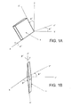
- FIGS. 1A and 1B illustrate the cutting orientation of an SC-cut crystal blank
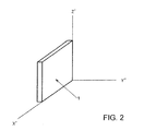
- FIG. 2 shows the relationship between an SC-cut crystal blank cut out from a crystal of quartz and the crystal axes of the quartz.
- FIG. 1A a plane orthogonal to a Y-axis of a crystal of quartz is rotated by an angle of ⁇ centering around an X-axis from the Y-axis toward a Z-axis, that is, as a counterclockwise rotation.
- this rotation the Y-axis and the Z-axis change to a Y'-axis and a Z'-axis, respectively.
- this plane is rotated by an angle of ⁇ centering around the Z'-axis as a rotation from the X-axis toward the Y'-axis, that is, a counterclockwise rotation.
- a crystal blank which is cut out from a crystal of quartz along a plane which is obtained by subjecting a Y-cut plate to the two rotation operations is an SC-cut crystal blank. It is noted that even if the order of the two rotation operations is reversed, that is, when firstly rotated by an angle of ⁇ around the Z-axis and thereafter rotated by an angle of ⁇ around the new X'-axis, the same result will be obtained.
- a quartz crystal plate which is cut with its principal plane being orthogonal to the Y"-axis is called a double-rotation Y-cut plate.
- the principal plane of crystal blank 1 which is to be cut out is a plane defined by the X'-axis and the Z'-axis, and the thickness direction of crystal blank 1 is parallel with the Y"-axis.
- An SC-cut crystal blank is one in which the reference angles of rotational angles are set as 33 degrees for ⁇ and 22 degrees for p in such a double-rotation Y-cut plate.
- the reference angle is an angle which provides a reference of cutting orientation when a crystal blank is designed and a value near the reference value is appropriately selected depending on the desired temperature characteristics and the like of the crystal blank when the crystal blank is actually cut out.
- a circular excitation electrode for exciting thickness-shear vibration in crystal blank 1 is formed in the central region of each of the principal planes of crystal blank 1 as shown in FIGS. 3A and 3B , and thus an SC-cut crystal element is obtained.
- Thickness-shear vibration in quartz has a resonance frequency corresponding to the thickness of crystal blank 1; the resonance frequency increases as the thickness of crystal blank 1 decreases.
- leader electrode 3 described below extends from each of excitation electrode 2 toward the outer peripheral part of crystal blank 1 as shown in FIG. 4 . Then, the crystal blank is held electrically and mechanically at the position where leader electrodes 3 extend, and the crystal blank is hermetically encapsulated into a package with the state in which the crystal blank is held in this manner thereby completing a crystal unit.
- null stress-sensitivity axis Z'( ⁇ ) which is the axis obtained by rotating the Z'-axis by an angle of ⁇ toward the X'-axis, that is, in a counterclockwise direction, depending on the crystal structure in the SC-cut plate which is a double-rotation Y-cut plate
- null stress-sensitivity axis X'( ⁇ ) which is the axis perpendicular to null stress-sensitivity axis Z'( ⁇ ), that is, the axis obtained by rotating the X'-axis by an angle of ⁇ .
- a null stress-sensitivity axis refers to the axis of which frequency variation becomes minimum including the case of zero when stress is applied from both sides of crystal blank 1 along its axis.
- the reference angle of angle ⁇ is about 8 degrees in an SC-cut plate.
- the resonance frequency of a crystal blank varies when stress is applied thereto, and it may be changed by the stress applied from the mechanism to hold the crystal blank. Accordingly, to minimize such variation of the resonance frequency, it is preferable to hold the crystal blank at both ends of the null stress-sensitivity axis.
- crystal blank 1 is arranged to be cut out from a crystal of quartz such that two mutually orthogonal null stress-sensitivity axes Z'( ⁇ ) and X'( ⁇ ) become respectively a pair of diagonal lines of the square as shown in FIG. 4 .
- Leader electrodes 3 are, for example, configured to extend from excitation electrodes 2 to both ends of the diagonal line which becomes one null stress-sensitivity axis Z'( ⁇ ). Then, by holding both ends, to which leader electrodes 3 are extended, with a mechanism (not shown), the crystal blank is electrically and mechanically held at two points. When enhancing the strength of the crystal element against mechanical impact, the crystal blank is further held at both ends of the other null stress-sensitivity axis X'( ⁇ ) such that the crystal blank is eventually held at four points. The crystal blank thus held at two or four points is hermetically encapsulated in a package as described above.
- each four corner of crystal blank 1 is located farthest from the central region which serves as the vibration region in the crystal blank, it is possible to reduce the effect on the vibration characteristics at the central region by extending leader electrode 3 toward each corner and holding the crystal blank at the corner.
- crystal blank 1 it is also possible to configure crystal blank 1 to have a circular planar shape, since it becomes difficult to recognize the position of the null stress-sensitivity axis when a circular shape is employed, the position of the null stress-sensitivity axis becomes more recognizable thereby making the holding operation of the crystal blank to be easier when the crystal blank is configured to have a rectangular planar shape.
- the thickness-shear vibration in an SC-cut plate exhibits a vibration displacement distribution in which vibration is emphasized for example in the hatched area shown in FIG. 5 . That is, the central region of the crystal blank is divided into four regions shown in the figure by mutually orthogonal null stress-sensitivity axes Z'( ⁇ ) and X'( ⁇ ), and each divided region respectively has an emphasized vibration displacement.
- the magnitudes of the vibration displacement in these four emphasized portions are approximately the same.
- the center of each region where vibration displacement is emphasized is shown by a solid point, and these four center points are positioned approximately at corners of a square as shown by a chain line in the figure.
- the direction which is along the line orthogonal to a diagonal direction of the crystal blank, and which avoids the four portions of emphasized vibration displacement becomes the above described null stress-sensitivity axis Z'( ⁇ ) or X'( ⁇ ), since it does not affect the vibration displacement.
- one principal plane of the crystal blank is processed to be a flat plane and the other principal plane is processed to be a convex-shape, thereby forming a so called plano-convex shape.
- examples of the crystal element made of a double-rotation Y-cut plate include an IT-cut quartz crystal element in which the above described angles of ⁇ and ⁇ are different from those of the SC-cut crystal element, as disclosed in U.S. Patent No. 7,001,887 .
- the reference angle of angle ⁇ is 34 degrees and the reference angle of angle ⁇ is 19 degrees.
- the vibration characteristics of the crystal element is superior in vibration characteristics such as stress sensitivity characteristics and thermal shock property as described above, the vibration characteristics will significantly vary due to a slight difference in the angle when cutting out the crystal blank.
- the vibration characteristics of the crystal element sensitively responds to the cutting orientation as a double-rotation Y-cut plate for forming an SC-cut plate, and the cutting angle in the plane when forming a rectangular crystal blank such that its corners are positioned at the positions inclined by 8 degrees from the Z'-axis or the X'-axis.
- an SC-cut crystal element has a frequency-temperature characteristics which can be represented by a cubic curve of which inflection point is positioned at about 90 °C of temperature, this frequency-temperature characteristics will significantly vary and also the crystal impedance (CI) will degrade due to a slight error in the cutting orientation and cutting angle.
- CI crystal impedance
- crystal blank 1 When crystal blank 1 has a shape other than a square, for example, a circular or rectangular shape, the vibration characteristics will sensitively respond to even a slight deviation of the holding position from the position inclined 8 degrees from Z'-axis or X'-axis.
- the object of the present invention is achieved by a crystal element made of a double-rotation Y-cut plate, the crystal element comprising a crystal blank which is cut from a crystal of quartz, a principle plane of the crystal blank being orthogonal to a Y"-axis, where a Y-axis and a Z-axis are rotated by an angle of ⁇ centering around an X-axis in the crystal of quartz to be designated as a Y'-axis and a Z'-axis, and the X-axis and the Y'-axis are rotated by an angle of ⁇ centering around the Z'-axis to be designated as an X'-axis and the Y"-axis; wherein the crystal blank has mutually orthogonal two null stress-sensitivity axes and has emphasized vibration displacement in four regions radially divided from a center at which the null stress-sensitivity axes mutually intersect at a right angle; wherein the thickness of a center part at which the null stress-sensitivity
- the emphasized vibration displacement in the four regions between mutually orthogonal null stress-sensitivity axes is confined into each of the four thickened regions between the orthogonal null stress-sensitivity axes. Even if some deviation occurs in the cutting orientation, cutting angle, and holding position of a crystal blank which is a double-rotation Y-cut plate, the energy of the vibration displacement in the four regions is confined into those four regions, and the leakage thereof is restricted thereby preventing the mutual interference between regions having emphasized vibration displacement. Therefore, it is possible to prevent the degradation of CI due to the leakage of vibration energy and the variation of the frequency-temperature characteristics due to the mutual interference. Thus, it is made possible to obtain a crystal element made of a double-rotation Y-cut plate, which is superior in vibration characteristics and is easy to design and manufacture.
- FIG. 7 shows a quartz crystal element made of a double-rotation Y-cut plate according to a first embodiment of the present invention. Particularly, FIG. 7 illustrates a quartz crystal blank constituting the crystal element.
- the double-rotation Y-cut plate is an SC-cut quartz plate.
- the SC-cut crystal element uses crystal blank 1 which has a principal plane orthogonal to a Y"-axis, where the Y-axis is rotated twice with rotation angles (reference angles) ⁇ and ⁇ from the crystallographic X-axis and Z-axis of quartz being 22 degrees and 33 degrees, respectively, and resulting three axes are designated as an X'-axis, a Y"-axis, and a Z'-axis (see FIG. 2 ).
- Crystal blank 1 here is configured to have a square planar shape as well, so that diagonal lines which are inclined by an angle of ⁇ from the Z'-axis and the X'-axis, respectively, are null stress-sensitivity axes Z'( ⁇ ) and X'( ⁇ ). Where ⁇ is 8 degrees.
- one principal plane of crystal blank 1 which is an SC-cut plate is formed into a quadrangular pyramid like shape with its center point being the vertex. Specifically, there are formed triangular inclined surfaces of which bases are respective four sides of the crystal blank, and of which width is gradually increased from the vertex (or vertex potion) to each base, and ridge line portion P is formed between those inclined surfaces.
- the center point of the principal plane of crystal blank 1 corresponds to the point at which two null stress-sensitivity axes intersect at a right angle.
- crystal blank 1 each have a convex curved shape of the same curvature in the direction orthogonal to peripheral sides (bases) of the crystal blank, and accordingly the ridge line portion is also formed into a curved shape.
- the end faces at each position of four sides basically have the same thickness "t".
- the other principal plane of crystal blank 1 is processed to be a flat plane. That is, crystal blank 1 has a shape in which a quadrangular pyramid of which each side face is formed of a convex curved surface is placed on one principal plane of the base plate portion having a uniform thickness t.
- Crystal blank 1 having such a shape can be processed by using grinding plate 4 formed into a half cylinder shape, for example, as shown in FIG. 8 .
- four sides of crystal blank 1 are arranged so as to be consistent with the directions of the width and length of grinding plate 4.
- grinding plate 4 is pivoted in the width direction as shown in arrow B while one principal plane of crystal blank is pressed against grinding plate 4, and is further moved back and forth in length direction C.
- Such relative movement between grinding plate 4 and crystal blank 1 makes one principal plane of crystal blank 1 to be processed into a convex curved surface along the inner periphery of grinding plate 4, and this convex curved surface linearly extends in the shown direction C.
- grinding is performed such that constant thickness t of the crystal blank is remained in the end faces of crystal blank 1 along the direction C.
- crystal blank 1 is rotated by 90 degrees and is similarly ground such that the thickness t is remained.
- each inclined surface is configured to be a convex curved surface having a curvature which imitates the inner periphery of grinding plate 4 from the vertex portion toward each side of the crystal blank.
- ridge line portion P is also formed into a convex curve, its curve is gentler than the curvature of grinding plate 4.
- each excitation electrode 2 is provided in a circular shape, and leader electrodes 3 are extended from excitation electrodes 2 toward both ends of the diagonal part which is one null stress-sensitivity axis Z'( ⁇ ).
- the SC-cut crystal element formed with excitation electrodes 2 and leader electrodes 3 as described above is held at two points by holding both ends of the diagonal line which is one null stress-sensitivity axis Z'( ⁇ ), or is held at four points by holding both ends of the diagonal lines corresponding to both null stress-sensitivity axes X'( ⁇ ) and Z'( ⁇ ) and is hermetically encapsulated in a package for crystal element.
- a crystal unit is completed.
- FIG. 9A is a plan view of crystal blank 1 described above and the dashed line in the figure is the line to show the contour, that is the positions at which the thickness of crystal blank 1 is a certain fixed value.
- the section thickness in the vertical direction is the same on the sides of the square for each square concentrically positioned with respect to the center point of the crystal blank. Therefore, the vertical section of the crystal blank on the line parallel with each side of crystal blank 1 is as shown FIG. 9B.
- FIG. 9B is a sectional view of crystal blank 1 taken along line A-A of FIG. 9A . That is, sectional thickness in the width direction across the each inclined surface of triangular shape on one principal plane of crystal blank 1 will be the same.
- the thickness becomes gradually smaller on an adjacent inclined surface bounded by ridge line portion P. Therefore, the section taken along A-A line becomes a so-called bevel shape, in which the thickness in the central region is large, and both sides bounded by ridge line portions P are inclined thereby decreasing the thickness.
- each ridge line P corresponds to mutually orthogonal null stress-sensitivity axes Z'( ⁇ ) and X'( ⁇ ) of crystal blank 1.
- the region which exhibits emphasized vibration displacement, and which is separated by null stress-sensitivity axes Z'( ⁇ ) and X'( ⁇ ) takes place on each of four inclined surfaces. Further, since in the region in which vibration displacement is emphasized in each inclined surface, the section on the line parallel with each outer periphery of each inclined surface is formed into a bevel shape, the vibration energy (vibration displacement) therein is forcibly confined.
- ridge line P in one principal plane of crystal blank 1 becomes a boundary condition when increasing the thickness of the central region and gradually decreasing the sectional thickness on both sides in each section. Therefore, as shown in FIG. 10 , emphasized vibration displacement is confined in the four portions which are between ridge line portions P and the separation of the positions of the four vibration displacement regions becomes clear.
- the region in which vibration displacement is emphasized will be confined into sections divided by ridge line portion P. Even if there is an error in the cutting orientation when cutting out an SC-cut plate, or there is a deviation in the cutting angle within a plane when forming a square crystal blank such that the diagonal direction corresponds to null stress-sensitivity axes Z'( ⁇ ) and X'( ⁇ ), or there is deviation in the holding position of the crystal blank caused by the deviation in the cutting angle, it is possible to maintain the frequency-temperature characteristics depending on vibration displacement distribution and the vibration characteristics such as CI etc. of the crystal element in a good state. According to the present embodiment, it becomes easy to design and manufacture a crystal element of which vibration characteristics is well maintained.
- one principal plane of crystal blank 1 is processed in a quadrangular pyramid like shape of which center part is the vertex or apex, and further the vertex portion of the quadrangular pyramid may be processed into a flat surface shape as shown in FIGS. 11A and 11B .
- a flat surface shape is a fully flat plane or a convex curved surface with a small curvature.
- Such flat surface may be formed by bringing the center part of one principal plane of crystal blank 1 in abutment with a grinding plate (not shown) having a planer surface or a spherical surface with a small curvature after the processing to form a quadrangular pyramid like shape.
- vertex portion 5 of crystal blank 1 is processed into a planer surface in the case shown in FIG. 11A
- vertex portion 5 is processed into a spherical surface shape with a small curvature in the case shown in FIG. 11B .
- the curvature of vertex portion 5 may be smaller than the curvature of the inclined surface of the quadrangular pyramid.
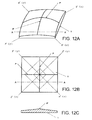
- FIG. 12A shows a crystal element made of a double-rotation Y-cut plate according to a second embodiment of the present invention.
- the double-rotation Y-cut plate is an SC-cut plate.
- FIG. 12A shows a crystal blank in such SC-cut crystal element.
- like components as in the above described each figure are given like reference symbols, thereby simplifying or omitting redundant description.
- ridge line portion P is provided so as to extend in the diagonal direction in the first principal plane of crystal blank 1 having a square planer shape.
- ridge line portion P is configured to be the line connecting middle points of opposing sides of a pair for each of the two pairs of opposing sides of crystal blank 1. That is, ridge line P is provided in a cross shape so as to connect the middle point of each side of the outer periphery of crystal blank 1.
- such crystal blank 1 may be ground such that the diagonal direction of crystal blank 1 is oriented in the length direction of grinding plate 4, in contrast to the case of the first embodiment.
- each diagonal direction of the crystal blank is mutually orthogonal null stress-sensitivity axes Z'( ⁇ ) and X'( ⁇ ).
- FIG. 12B is a plan view of crystal blank 1 in the second embodiment, and the dash line in the figure represents a contour.
- FIG. 12C is a sectional view of crystal blank 1 taken along A-A line in FIG. 12B .
- the positions at which the thickness becomes same in crystal blank 1 are the sides of a square interconnecting four points at an equal distance from the intersection on this ridge line P, when considering the intersection of two ridge lines P.
- the sides of this square can be considered to be bases of the quadrangular pyramid having a vertex at the intersection of ridge lines P.
- the section along the line parallel with each side of crystal blank, for example, the section taken along A-A line becomes an inclined surface of which center point in the width direction is ridge line P, and of which thickness is maximum at ridge line P and gradually becomes smaller toward both sides.
- the vibration displacement of four regions between mutually orthogonal null stress-sensitivity axes Z'( ⁇ ) and X'( ⁇ ) in the central region of crystal blank 1 will be confined into the region having a large thickness in crystal blank 1 on the center line interconnecting the middle points of opposing sides of each pair. Therefore, by the second embodiment as well, even if there is some angle deviation in the cutting orientation and planar cutting in the SC-cut crystal blank, it is possible to maintain the vibration characteristics of crystal element well. Further, it is possible to easily design and manufacture such a crystal element.
- ridge line portion P in a convex curved shape with a small curvature in the center part of one principal plane of crystal blank 1.
- the region of ridge line P in the center part may be ground to form a region with a smaller curvature by rotating crystal blank 1 by a grinding plate which is configured to be a sphere shape with a curvature not more than the curvature along ridge line P in the direction across the center of crystal blank 1.
- any processing means it is also possible to make only the intersection region of ridge lines to be a curved shape. As a result of these, it is possible to make a smooth ridge line, at which adjacent inclined surfaces of a quadrangular pyramid like shape intersect thereby forming a boundary, and to confine vibration into a region of large thickness, as well as to easily generate vibration since the boundary condition for vibration is removed.
- null stress-sensitivity axes Z'( ⁇ ) and X'( ⁇ ) may be in the direction along each side of the square. In that case, the crystal blank is held at middle points of opposing sides, so that those points become both ends of null stress-sensitivity axes Z'( ⁇ ) and X'( ⁇ ).
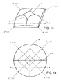
- the shape of crystal blank 1 is not limited to a square.
- the crystal blank to which the present invention is applied may be a circular crystal blank for example as shown in FIG. 14 , or a rectangular crystal blank which is not shown though.
- the sectional thickness of crystal blank 1 is larger in the central region, that is, at the position of ridge line P and becomes smaller toward both ends, along this line.
- the double-rotation Y-cut plate to which the present invention is applied is not limited to the SC-cut plate.
- the preset invention can be similarly applied to an IT-cut quartz plate with the above described angle ⁇ being 34 degrees and angle ⁇ being 19 degrees.
- the direction of null stress-sensitivity axis in an IT-cut plate is, as with an SC-cut plate, the direction rotated by 8 degrees from Z'-axis and the direction orthogonal to this direction, that is the direction rotated by 8 degrees from the X'-axis.
- the present invention may be applied to others, besides the SC-cut plate and the IT-cut plate, if they are a double-rotation Y-cut plate having a similar vibration displacement distribution.
Landscapes
- Physics & Mathematics (AREA)
- Acoustics & Sound (AREA)
- Piezo-Electric Or Mechanical Vibrators, Or Delay Or Filter Circuits (AREA)
- Crystals, And After-Treatments Of Crystals (AREA)
Applications Claiming Priority (1)
| Application Number | Priority Date | Filing Date | Title |
|---|---|---|---|
| JP2007271675A JP4563437B2 (ja) | 2007-10-18 | 2007-10-18 | 2回回転yカット板からなる水晶振動子 |
Publications (1)
| Publication Number | Publication Date |
|---|---|
| EP2051374A1 true EP2051374A1 (fr) | 2009-04-22 |
Family
ID=40243775
Family Applications (1)
| Application Number | Title | Priority Date | Filing Date |
|---|---|---|---|
| EP20080166794 Withdrawn EP2051374A1 (fr) | 2007-10-18 | 2008-10-16 | Élément de cristal de quartz fabriqué à partir d'une plaque de cristal de quartz coupée en Y par double rotation |
Country Status (4)
| Country | Link |
|---|---|
| US (1) | US7863802B2 (fr) |
| EP (1) | EP2051374A1 (fr) |
| JP (1) | JP4563437B2 (fr) |
| CN (1) | CN101478298B (fr) |
Cited By (7)
| Publication number | Priority date | Publication date | Assignee | Title |
|---|---|---|---|---|
| WO2016048408A1 (fr) * | 2014-09-25 | 2016-03-31 | Nassim Haramein | Cristaux à haute énergie taillés avec précision |
| US9435054B1 (en) | 2013-09-27 | 2016-09-06 | Torus Tech Llc | Precision cut high energy crystals |
| EP3198062A4 (fr) * | 2014-09-25 | 2017-09-27 | Torus Tech LLC | Cristaux à haute énergie taillés avec précision |
| CN107231139A (zh) * | 2016-03-23 | 2017-10-03 | 日本电波工业株式会社 | 晶体振子 |
| US10861350B2 (en) | 2011-11-14 | 2020-12-08 | Ark Crystal, LLC | Modular frames for arrangement and orientation of geometric solids |
| RU2786419C2 (ru) * | 2014-09-25 | 2022-12-21 | Арк Кристал, Ллс | Высокоэнергетические кристаллы, полученные прецизионной резкой |
| KR20260000592A (ko) | 2024-06-24 | 2026-01-05 | 한국생산기술연구원 | 에스터기 및 아미드기를 갖는 신규한 경화제, 이의 제조방법, 이를 포함하는 에폭시 조성물, 경화물 및 물품 |
Families Citing this family (14)
| Publication number | Priority date | Publication date | Assignee | Title |
|---|---|---|---|---|
| US9046395B2 (en) | 2011-03-10 | 2015-06-02 | Spirax Sarco, Inc. | Vortex shedding flow meter |
| JP2012199606A (ja) * | 2011-03-18 | 2012-10-18 | Nippon Dempa Kogyo Co Ltd | 水晶振動片及び水晶デバイス |
| JP5887968B2 (ja) * | 2012-02-03 | 2016-03-16 | セイコーエプソン株式会社 | Scカット水晶基板、振動素子、電子デバイス、発振器、及び電子機器 |
| US9762206B2 (en) * | 2014-02-07 | 2017-09-12 | Samsung Electro-Mechanics Co., Ltd. | AT-cut quartz crystal vibrator with a long side along the X-axis direction |
| CN104328497B (zh) * | 2014-11-19 | 2016-08-24 | 四川省三台水晶电子有限公司 | 一种sc切或it切晶片的制备方法 |
| US10224776B2 (en) * | 2015-06-03 | 2019-03-05 | General Electric Company | Retention assembly for stator bar using shim with stator wedge and related method |
| CN107636963B (zh) * | 2015-06-12 | 2020-07-28 | 株式会社村田制作所 | 石英片以及石英振子 |
| CN107636962B (zh) * | 2015-06-12 | 2020-07-31 | 株式会社村田制作所 | 石英片以及石英振子 |
| CN105007056A (zh) * | 2015-07-22 | 2015-10-28 | 成都泰美克晶体技术有限公司 | 一种具有单凸结构的压电石英晶片 |
| KR102170010B1 (ko) | 2016-01-08 | 2020-10-26 | 아르코닉 테크놀로지스 엘엘씨 | 새로운 6xxx 알루미늄 합금, 및 그의 제조 방법 |
| JP5943160B2 (ja) * | 2016-02-08 | 2016-06-29 | セイコーエプソン株式会社 | Scカット水晶基板、振動素子、電子デバイス、発振器、及び電子機器 |
| JP2017158146A (ja) * | 2016-03-04 | 2017-09-07 | 日本電波工業株式会社 | 水晶振動子 |
| JP2017192032A (ja) * | 2016-04-13 | 2017-10-19 | 日本電波工業株式会社 | 水晶振動子 |
| WO2021053519A1 (fr) * | 2019-09-16 | 2021-03-25 | Rakon Limited | Résonateurs à quartz à double rotation ayant une sensibilité réduite à l'accélération |
Citations (7)
| Publication number | Priority date | Publication date | Assignee | Title |
|---|---|---|---|---|
| US4124809A (en) * | 1972-05-30 | 1978-11-07 | Societe Suisse Pour L'industrie Horlogere Management Services S.A. | Quartz crystal resonator |
| US4375604A (en) * | 1981-02-27 | 1983-03-01 | The United States Of America As Represented By The Secretary Of The Army | Method of angle correcting doubly rotated crystal resonators |
| US4568850A (en) * | 1985-02-11 | 1986-02-04 | The United States Of America As Represented By The Secretary Of The Army | Doubly rotated cylindrical crystal resonator |
| JPH04138708A (ja) | 1990-09-29 | 1992-05-13 | Nippon Dempa Kogyo Co Ltd | Scカットの水晶振動子 |
| JP2000040937A (ja) | 1998-07-21 | 2000-02-08 | Nippon Dempa Kogyo Co Ltd | Scカットの水晶振動子 |
| US7001887B2 (en) | 2001-02-02 | 2006-02-21 | Chugai Seiyaku Kabushiki Kaisha | Peptide derivatives |
| US7011887B2 (en) * | 2002-09-02 | 2006-03-14 | Nihon Dempa Kogyo Co., Ltd. | IT-cut quartz crystal unit |
Family Cites Families (13)
| Publication number | Priority date | Publication date | Assignee | Title |
|---|---|---|---|---|
| US2261791A (en) * | 1939-04-29 | 1941-11-04 | Rca Corp | Piezoelectric thickness-mode quartz crystal |
| JPS5291673A (en) * | 1976-01-29 | 1977-08-02 | Seiko Instr & Electronics Ltd | Thickness sliding vibrator |
| JPS5938764B2 (ja) * | 1977-02-09 | 1984-09-19 | 株式会社精工舎 | 厚みすべり水晶振動子 |
| DE2752734B1 (de) * | 1977-11-25 | 1979-04-26 | Siemens Ag | Als Obertonresonator verwendeter Dickenscherschwinger |
| US4381471A (en) * | 1981-03-23 | 1983-04-26 | The United States Of America As Represented By The Secretary Of The Army | SC-Cut quartz resonators with suppressed b-mode |
| JPS59107618A (ja) * | 1982-12-13 | 1984-06-21 | Fujitsu Ltd | 水晶振動子の製造方法 |
| FR2634067B1 (fr) * | 1988-07-07 | 1992-04-03 | Electro Microtechn Centre | Resonateur piezoelectrique |
| JP3231055B2 (ja) * | 1991-08-31 | 2001-11-19 | 日本電波工業株式会社 | Scカットの水晶振動子 |
| US6744182B2 (en) * | 2001-05-25 | 2004-06-01 | Mark Branham | Piezoelectric quartz plate and method of cutting same |
| JP4069773B2 (ja) * | 2003-03-19 | 2008-04-02 | セイコーエプソン株式会社 | 圧電振動片、圧電振動子および圧電デバイス |
| US7705524B2 (en) * | 2003-07-18 | 2010-04-27 | Nihon Dempa Kogyo Co., Ltd. | SC cut crystal resonator |
| JP4138708B2 (ja) | 2004-07-12 | 2008-08-27 | 浜松ホトニクス株式会社 | 光検出装置 |
| US20100148782A1 (en) * | 2008-12-15 | 2010-06-17 | Schlumberger Technology Corporation | Rugged quartz clock |
-
2007
- 2007-10-18 JP JP2007271675A patent/JP4563437B2/ja not_active Expired - Fee Related
-
2008
- 2008-10-16 EP EP20080166794 patent/EP2051374A1/fr not_active Withdrawn
- 2008-10-17 CN CN2008101366950A patent/CN101478298B/zh not_active Expired - Fee Related
- 2008-10-20 US US12/254,079 patent/US7863802B2/en not_active Expired - Fee Related
Patent Citations (7)
| Publication number | Priority date | Publication date | Assignee | Title |
|---|---|---|---|---|
| US4124809A (en) * | 1972-05-30 | 1978-11-07 | Societe Suisse Pour L'industrie Horlogere Management Services S.A. | Quartz crystal resonator |
| US4375604A (en) * | 1981-02-27 | 1983-03-01 | The United States Of America As Represented By The Secretary Of The Army | Method of angle correcting doubly rotated crystal resonators |
| US4568850A (en) * | 1985-02-11 | 1986-02-04 | The United States Of America As Represented By The Secretary Of The Army | Doubly rotated cylindrical crystal resonator |
| JPH04138708A (ja) | 1990-09-29 | 1992-05-13 | Nippon Dempa Kogyo Co Ltd | Scカットの水晶振動子 |
| JP2000040937A (ja) | 1998-07-21 | 2000-02-08 | Nippon Dempa Kogyo Co Ltd | Scカットの水晶振動子 |
| US7001887B2 (en) | 2001-02-02 | 2006-02-21 | Chugai Seiyaku Kabushiki Kaisha | Peptide derivatives |
| US7011887B2 (en) * | 2002-09-02 | 2006-03-14 | Nihon Dempa Kogyo Co., Ltd. | IT-cut quartz crystal unit |
Non-Patent Citations (1)
| Title |
|---|
| TIERSTEN H F ET AL: "An analysis of the normal acceleration sensitivity of contoured quartz resonators rigidly supported along the edges", ULTRASONICS SYMPOSIUM 1988, vol. 1, 2 October 1988 (1988-10-02), pages 357 - 363, XP010075471 * |
Cited By (13)
| Publication number | Priority date | Publication date | Assignee | Title |
|---|---|---|---|---|
| US10861350B2 (en) | 2011-11-14 | 2020-12-08 | Ark Crystal, LLC | Modular frames for arrangement and orientation of geometric solids |
| US11908341B2 (en) | 2011-11-14 | 2024-02-20 | Ark Crystal, LLC | Modular frames for arrangement and orientation of geometric solids |
| US9435054B1 (en) | 2013-09-27 | 2016-09-06 | Torus Tech Llc | Precision cut high energy crystals |
| US9745669B2 (en) | 2013-09-27 | 2017-08-29 | Ark Crystal, LLC | Precision cut high energy crystals |
| EP3198062A4 (fr) * | 2014-09-25 | 2017-09-27 | Torus Tech LLC | Cristaux à haute énergie taillés avec précision |
| US9834862B2 (en) | 2014-09-25 | 2017-12-05 | Ark Crystal, LLC | Precision cut high energy crystals |
| RU2668034C1 (ru) * | 2014-09-25 | 2018-09-25 | Арк Кристал, Ллс | Высокоэнергетические кристаллы, полученные прецизионной резкой |
| US10094046B2 (en) | 2014-09-25 | 2018-10-09 | Ark Crystal, LLC | Precision cut high energy crystals |
| US10612158B2 (en) | 2014-09-25 | 2020-04-07 | Ark Crystal, LLC | Precision cut high energy crystals |
| RU2786419C2 (ru) * | 2014-09-25 | 2022-12-21 | Арк Кристал, Ллс | Высокоэнергетические кристаллы, полученные прецизионной резкой |
| WO2016048408A1 (fr) * | 2014-09-25 | 2016-03-31 | Nassim Haramein | Cristaux à haute énergie taillés avec précision |
| CN107231139A (zh) * | 2016-03-23 | 2017-10-03 | 日本电波工业株式会社 | 晶体振子 |
| KR20260000592A (ko) | 2024-06-24 | 2026-01-05 | 한국생산기술연구원 | 에스터기 및 아미드기를 갖는 신규한 경화제, 이의 제조방법, 이를 포함하는 에폭시 조성물, 경화물 및 물품 |
Also Published As
| Publication number | Publication date |
|---|---|
| US20090102326A1 (en) | 2009-04-23 |
| CN101478298B (zh) | 2012-12-26 |
| JP4563437B2 (ja) | 2010-10-13 |
| CN101478298A (zh) | 2009-07-08 |
| JP2009100375A (ja) | 2009-05-07 |
| US7863802B2 (en) | 2011-01-04 |
Similar Documents
| Publication | Publication Date | Title |
|---|---|---|
| US7863802B2 (en) | Quartz crystal element made of double-rotation Y-cut quartz crystal plate | |
| KR100517449B1 (ko) | 탄성 표면파 장치 및 탄성 표면파 장치의 온도 특성 조정방법 | |
| US9543923B2 (en) | Crystal resonator including blank and supporting portion | |
| EP1909391B1 (fr) | Oscillateur cristallin | |
| US7705524B2 (en) | SC cut crystal resonator | |
| JP2015122624A5 (fr) | ||
| JP2017192032A (ja) | 水晶振動子 | |
| CN102655400A (zh) | Gt切割石英晶体谐振器 | |
| CN1533030B (zh) | 压电振动片、压电振子及压电器件 | |
| US4454443A (en) | Quartz resonators for acceleration environments | |
| JP5435060B2 (ja) | 振動片 | |
| US20220345104A1 (en) | Doubly Rotated Quartz Crystal Resonators With Reduced Sensitivity to Acceleration | |
| JP4997780B2 (ja) | 圧電振動片の製造方法 | |
| US5041754A (en) | Crystal resonator with acceleration sensitivity adjustable by external circuit means | |
| US7011887B2 (en) | IT-cut quartz crystal unit | |
| US20170257077A1 (en) | Crystal resonator | |
| JP3980971B2 (ja) | Itカットの水晶振動子 | |
| JP2012175520A (ja) | 水晶振動子 | |
| WO2024189482A1 (fr) | Résonateurs de type qas à double rotation à sensibilité réduite à l'accélération | |
| EP4677747A1 (fr) | Résonateurs de type qas à double rotation à sensibilité réduite à l'accélération | |
| JP2007104042A (ja) | 水晶振動素子及びその製造方法 | |
| WO2016060204A1 (fr) | Oscillateur à quartz | |
| JP3550796B2 (ja) | 水晶振動子 | |
| JPH0320930B2 (fr) | ||
| JP2016082584A (ja) | 水晶振動子 |
Legal Events
| Date | Code | Title | Description |
|---|---|---|---|
| PUAI | Public reference made under article 153(3) epc to a published international application that has entered the european phase |
Free format text: ORIGINAL CODE: 0009012 |
|
| AK | Designated contracting states |
Kind code of ref document: A1 Designated state(s): AT BE BG CH CY CZ DE DK EE ES FI FR GB GR HR HU IE IS IT LI LT LU LV MC MT NL NO PL PT RO SE SI SK TR |
|
| AX | Request for extension of the european patent |
Extension state: AL BA MK RS |
|
| 17P | Request for examination filed |
Effective date: 20090528 |
|
| AKX | Designation fees paid |
Designated state(s): DE FR GB |
|
| 17Q | First examination report despatched |
Effective date: 20150211 |
|
| STAA | Information on the status of an ep patent application or granted ep patent |
Free format text: STATUS: THE APPLICATION IS DEEMED TO BE WITHDRAWN |
|
| 18D | Application deemed to be withdrawn |
Effective date: 20150623 |