WO2016060204A1 - Oscillateur à quartz - Google Patents
Oscillateur à quartz Download PDFInfo
- Publication number
- WO2016060204A1 WO2016060204A1 PCT/JP2015/079171 JP2015079171W WO2016060204A1 WO 2016060204 A1 WO2016060204 A1 WO 2016060204A1 JP 2015079171 W JP2015079171 W JP 2015079171W WO 2016060204 A1 WO2016060204 A1 WO 2016060204A1
- Authority
- WO
- WIPO (PCT)
- Prior art keywords
- crystal
- axis
- plate
- plates
- quartz
- Prior art date
- Legal status (The legal status is an assumption and is not a legal conclusion. Google has not performed a legal analysis and makes no representation as to the accuracy of the status listed.)
- Ceased
Links
Images







Classifications
-
- H—ELECTRICITY
- H03—ELECTRONIC CIRCUITRY
- H03H—IMPEDANCE NETWORKS, e.g. RESONANT CIRCUITS; RESONATORS
- H03H9/00—Networks comprising electromechanical or electro-acoustic elements; Electromechanical resonators
- H03H9/15—Constructional features of resonators consisting of piezoelectric or electrostrictive material
- H03H9/17—Constructional features of resonators consisting of piezoelectric or electrostrictive material having a single resonator
- H03H9/19—Constructional features of resonators consisting of piezoelectric or electrostrictive material having a single resonator consisting of quartz
Definitions
- the present invention relates to a crystal resonator.
- Quartz resonators used as frequency and time reference sources are divided into several types of “cuts” according to the crystallographic orientation of the crystal plates that make up the crystal units, that is, when the crystal plates are cut from a single crystal of crystal. being classified.
- cuts for example, AT cuts, SC cuts, and the like are widely known.
- the GT-cut quartz plate has excellent frequency temperature characteristics, and the change in the resonance frequency when the ambient temperature changes is very small. Therefore, it is expected to be applied to a highly accurate and stable crystal oscillator.
- the rectangular GT-cut crystal resonator can be downsized in a low frequency band (for example, 2 to 10 MHz), and has a frequency temperature characteristic such that the primary temperature coefficient becomes 0 at room temperature (around 25 ° C.). Have.
- quartz crystal has three crystal axes that are crystallographically defined as an X axis, a Y axis, and a Z axis.
- ⁇ and ⁇ are parameters generally used to specify the cut direction in the crystal.
- the X, Y, and Z axes are obtained by rotating the X, Y, and Z axes around the X axis by + 51.5 °, respectively.
- the Z ′ axis Since the rotation is about the X axis, the X ′ axis naturally coincides with the X axis.
- the axes obtained by rotating the X ′ axis and the Z ′ axis by 45 ° around the Y ′ axis in the direction from the Z ′ axis to the X ′ axis are defined as an X ′′ axis and a Z ′′ axis, respectively.
- the vibration mode in the GT-cut quartz plate 11 is a vibration mode (width / length) in which a longitudinal vibration (stretching vibration) mode in the X ′′ axis direction and a longitudinal vibration mode in the Z ′′ axis direction are combined. Also referred to as a longitudinally coupled vibration mode).
- the direction of the stretching vibration is indicated by an arrow, and the contour displaced by the vibration is indicated by a broken line.
- the displaced contour is depicted as being much larger than the actual amount of displacement in the quartz plate 11.
- the conventional GT-cut quartz plate has a pair of sides parallel to the X ′′ axis and another pair of sides parallel to the Z ′′ axis.
- a rectangular or square shape was used as a diaphragm in a crystal resonator.
- Excitation electrodes for exciting the crystal plate as the vibration plate are respectively provided on both main surfaces of the crystal plate.
- the longitudinal vibration mode is used as the main vibration, the GT-cut quartz plate can be formed in a small size even when the resonance frequency is in the low frequency band.
- the GT-cut vibrator vibrates in a vibration mode called a lame vibration mode different from the width / length longitudinally coupled vibration mode when the length of each side is equal and a square diaphragm is used.
- the plane shape of the GT-cut vibrator is not square.
- the vibration mode of the quartz plate is different for each cut.
- the vibration mode is a thickness-shear vibration mode, and the resonance frequency is determined only by the thickness. Therefore, in the AT-cut quartz plate, the plane shape can be arbitrarily set, and thereby, the quartz piece can be supported at a position that becomes a fixed point in the thickness shear vibration.
- the vibration mode is the width / length longitudinally coupled vibration mode, the resonance frequency changes according to the planar shape and size such as width and length, and the two coupled to each other.
- the planar shape cannot be arbitrarily set, and the support portion cannot be arranged at any position.
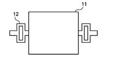
- the support portion 12 is connected to the midpoint position of each of a pair of opposing sides in the rectangular main body portion of the crystal plate 11 as the vibration plate. At this time, the support part 12 does not affect the vibration of the quartz plate 11 by providing a crank-like bent part. Further, by using a method such as the finite element method, the shape of the support portion 12 is set so that the resonance frequency of the vibration portion alone and the resonance frequency of the entire resonance system including the support portion 12 are substantially the same. To design.
- a GT-cut quartz crystal resonator having a support portion as shown in FIG. 2 is complicated in structure and difficult to manufacture, and the size of the support portion itself cannot be ignored compared to the main body of the diaphragm.
- the dimensional variation in the support portion has a great influence on the vibration characteristics of the quartz plate and inhibits the miniaturization of the quartz resonator.
- an elliptical crystal plate as a diaphragm as a GT-cut crystal resonator (Patent Document 3).
- the quartz plate formed in an elliptical shape in which the vibration directions of two orthogonal longitudinal vibration modes in the GT cut are the major axis and the minor axis, respectively vibration displacement occurs on the outer periphery of the quartz plate when the two longitudinal vibration modes are combined. Since there are four positions that are minimal, by adopting a structure that supports the crystal plate at such points, even when a support portion with a simple structure is used, The quartz plate can be supported without adversely affecting the vibration characteristics.
- the present inventors have used a plurality of elliptical GT-cut quartz plates each acting as a resonator to increase the equivalent series capacitance C1 and reduce the equivalent series resistance ESR in a GT-cut quartz crystal resonator. Proposed a crystal resonator that is connected in a mechanical manner (Patent Document 4).
- the frequency, vibration characteristics, and frequency temperature characteristics are determined by the shape of a GT-cut crystal resonator.
- the frequency-temperature characteristics are determined by the shape of the ellipse (particularly, the ratio of the length of the major axis to the minor axis).
- An object of the present invention is to provide a support portion having a small and simple structure without adversely affecting vibration characteristics, and has a high degree of freedom in designing various characteristics including frequency, vibration characteristics, and frequency temperature characteristics.
- the object is to provide a crystal resonator.
- the crystal resonator of the present invention is obtained by rotating the crystallographic X-axis, Y-axis, and Z-axis of the crystal by an angle of ⁇ 65 ° or more and ⁇ 50 ° or less around the X-axis. Obtained by rotating the X ′ axis and the Z ′ axis around the Y ′ axis by an angle of 40 ° to 50 ° in the direction from the Z ′ axis to the X ′ axis.
- a crystal plate is cut out from the crystal parallel to the plane including the X ′′ axis and the Z ′′ axis, with the axes being the X ′′ axis and the Z ′′ axis, and the crystal plate is parallel to the X ′′ axis and the Z ′′ axis, respectively.
- a rectangle having sides is defined as a reference rectangle, and at least one pair of opposite sides of the reference rectangle is expanded outward from the reference rectangle, and the X ′′ axis direction and the Z ′′ axis direction are orthogonal directions.
- the crystal resonator of the present invention is a crystal in which a so-called Y plate is rotated around the X axis of the crystal and further rotated in the plane by an angle of 40 ° or more and 50 ° or less, like the GT-cut crystal resonator.
- a plate is used as a diaphragm. Therefore, the diaphragm is constituted by a so-called rotating Y plate.
- the difference between the crystal resonator of the present invention and the GT-cut crystal resonator is that the rotation angle ⁇ when the crystal Y plate is rotated around the X axis is determined in the range of ⁇ 65 ° ⁇ ⁇ ⁇ 50 °. It is.
- ⁇ When ⁇ is between ⁇ 54 ° and ⁇ 48 °, it is generally called an LQ 2 T-cut quartz plate.
- the shape of the quartz plate is not a simple rectangle as described below.
- the value of ⁇ can be made smaller than the value in a general LQ 2 T cut (because it is a negative value, it is larger as an absolute value).
- the rotation angle ⁇ is also a cutting angle when a rotating Y plate to be a vibration plate is cut out from a crystal of crystal.
- the shape of the crystal plate is not a rectangle having sides parallel to the X ′′ axis and the Z ′′ axis (referred to as a reference rectangle), but at least a pair of the reference rectangles face each other. The side is bulged outward from the reference rectangle.
- the crystal plate has a shape in which each of the four sides of the reference rectangle is expanded outward from the reference rectangle.
- the reference rectangle itself is a virtual one introduced to define the shape of the crystal plate, and the actual crystal plate has a particular difference in properties depending on whether it is inside or outside the reference rectangle. Do not mean.
- the shape of the reference rectangle may be a square, but in order to prevent excitation of the lame vibration mode, is the maximum dimension in the X ′′ axis direction different from the maximum dimension in the Z ′′ axis direction in the quartz plate? Or, the shape of the bulge needs to be different.
- the vibration displacement in the X ′′ axis direction or the Z ′′ axis direction is minimal when the two longitudinal vibration modes are combined at the position near the apex of the reference rectangle on the outer periphery of the crystal plate.
- the quartz plate is a position. Therefore, it is preferable to support the quartz plate at this position.
- a plurality of the above-described crystal plates are arranged along the X ′′ axis direction or the Z ′′ axis direction, and excitation electrodes are provided on both main surfaces of the crystal plates for each crystal plate.
- the plates may be mechanically coupled to each other and conductive paths may be formed between the excitation electrodes so that adjacent quartz plates are excited with opposite polarities.
- a quartz plate obtained by rotating a Y plate around the X axis and then rotating the Y plate by an angle of not less than 40 ° and not more than 50 ° in the plane, and the X ′′ axis and the Z ′′ axis.
- the vibrator can be further downsized.
- it is possible to hold the quartz plate at a point where the vibration displacement is minimized, and it is possible to construct a quartz resonator using a small and simple structure supporting portion without affecting the vibration characteristics. it can.
- the crystal resonator of the present invention uses the longitudinal vibration mode as the main vibration, it can be miniaturized even in a low frequency band.
- (A)-(d) is a top view which shows the example of the planar shape of the quartz plate in the quartz oscillator of the 1st Embodiment of this invention, respectively. It is a figure which shows distribution of the displacement amount of a Z "axial direction in the vibration displacement of a vibrator
- FIG. 7 is a cross-sectional view taken along line A-A ′ of FIG. 6.
- (A) is a figure explaining rotating a quartz plate in a surface and changing the dimension of a X "axial direction and the dimension of a Z" axial direction. It is a graph which shows the relationship between a side ratio and the primary temperature coefficient in a frequency temperature characteristic with respect to various rotation angles (theta). It is a graph which shows the relationship between rotation angle (theta) and the equivalent series capacity
- FIG. 13 is a diagram showing a vibration state of the crystal unit shown in FIG.
- FIG. 13A is a plan view showing another example of the crystal resonator according to the second embodiment
- FIG. 13B is a cross-sectional view taken along line C-C ′ of FIG. (A)
- (b) is a top view which shows another example of the crystal oscillator of 2nd Embodiment, respectively.
- FIG. 17 is a diagram illustrating vibration displacement of the quartz crystal resonator illustrated in FIG. 16, wherein (a) illustrates a distribution of displacement amounts in the X ′′ -axis direction in vibration displacement, and (b) illustrates Z ′′ -axis direction in vibration displacement. It is a figure which shows distribution of the displacement amount.
- (A), (b) is a top view which respectively shows another example of the crystal oscillator of 3rd Embodiment.
- 3A to 3D show examples of the planar shape of the crystal plate 31 used as the vibration plate in the crystal resonator according to the first embodiment of the present invention.
- Each of these quartz plates 31 rotates a Y plate (a plane perpendicular to the crystallographic Y-axis of the quartz crystal) around the X-axis of the quartz by an angle ⁇ , and further 40 ° to 50 ° in the plane.
- a quartz plate rotated by the following angle.
- the rotation angle ⁇ is in the range of ⁇ 65 ° ⁇ ⁇ ⁇ 50 °.
- the coordinate axes obtained by rotating the crystallographic X-axis, Y-axis, and Z-axis around the X-axis by an angle ⁇ are defined as the X′-axis, the Y′-axis, and the Z′-axis (therefore, the X′-axis).
- X ′ axis and Z ′ axis are rotated by an angle of 40 ° or more and 50 ° or less in the direction from the Z ′ axis to the X ′ axis, respectively.
- the quartz plate 31 is a quartz plate 31 having a plane parallel to the X ′′ axis and the Z ′′ axis.
- the quartz plate 31 has two orthogonal longitudinal vibration modes whose vibration directions are the X ′′ axis direction and the Z ′′ axis direction, respectively, and these longitudinal vibration modes are combined to form the X ′′ axis direction and the Z ′′ axis. It has a width-length longitudinally coupled vibration mode that alternately expands and contracts in the direction.
- the definitions of the X ′ axis, the Y ′ axis, the Z ′ axis, the X ′′ axis, and the Z ′′ axis described here are common to the following description and FIG. 3 and subsequent drawings.
- the crystal plate 31 when a rectangle having sides substantially parallel to the X ′′ axis and the Z ′′ axis is considered as the reference rectangle 30, the crystal plate 31 according to the first embodiment has each of the four sides of the reference rectangle 30. Is inflated outward of the reference rectangle 30.
- the reference rectangle is indicated by a one-dot chain line. Therefore, the reference rectangle 30 is inscribed in the outer periphery of the crystal plate 31 such that each vertex thereof is on the outer periphery of the crystal plate 31.
- the length in the X ′′ axis direction of the reference rectangle 30 is Lx
- the length in the Z ′′ axis direction is Lz.
- the maximum length in the X ′′ axis direction of the quartz plate 31 is a, and the length in the Z ′′ axis direction is b.
- Lx Lz may be satisfied, but a ⁇ b needs to be satisfied in order to suppress vibration due to an unintended vibration mode such as a lame vibration mode.
- a and b need to be relatively close to each other.
- Lx> Lz, a> b for the sake of explanation.
- the ratio of the length in the X ′′ axis direction to the length in the Z ′′ axis direction of the quartz plate 31 is referred to as a side ratio.
- each side of the reference rectangle 30 is expanded outward so that adjacent vertices of the reference rectangle 30 are connected by elliptical arcs.
- the two elliptical arcs connected to each other at the position of the vertex of the reference rectangle 30 are elliptical arcs cut out from different ellipses.
- the quartz plate 31 is not shaped as a single ellipse as a whole.
- Each ellipse that is the basis of each elliptical arc has, for example, a length of the minor axis with respect to the length of the major axis of 0.3 to 0.6.
- the crystal plate 31 shown in FIG. 3B has a shape in which the reference rectangle 30 is expanded outward by four triangles each having the base of each side of the reference rectangle 30. Therefore, the quartz plate 31 is formed in a convex octagon. Although not shown here, the convex hexagonal crystal plate 31 may be formed by inflating only a pair of opposing sides of the reference rectangle 30 outward with a triangle.
- the crystal plate 31 shown in FIG. 3C has a shape in which each side of the reference rectangle 30 is expanded outward by a cosine curve.
- the curve to be used is not limited to the cosine curve, and an arbitrary curve can be used.
- the crystal plate 31 shown in FIG. 3 (d) is formed in a dodecagonal shape as a whole by replacing each side of the reference rectangle 30 with a broken line composed of four line segments. At this time, it is not always necessary to have a convex decagonal shape, and may be a concave decagonal hexagon as shown in the figure.
- the shape is not limited to the octagon shown in FIG. 3B or the dodecagon shown in FIG. Alternatively, it may be a polygon with an arbitrary number of corners greater than a hexagon. 3 (a), FIG. 3 (c), and FIG. 3 (d), as in the case of FIG. 3 (b), only a pair of opposing sides of the reference rectangle 30 are outward.
- An inflated shape may be used.
- connection position of the support portion for supporting the crystal plate 31 in the crystal resonator of the first embodiment will be examined.
- FIG. 4 and 5 respectively show the amount of displacement in the Z ′′ -axis direction within the plate surface of the crystal plate 31 when the crystal plate 31 shown in FIG. 3A vibrates in the width / length longitudinally coupled vibration mode.
- the distribution and the distribution of the displacement amount in the X ′′ axis direction are obtained by simulation.
- a positive displacement amount indicates displacement in the positive direction of each axis
- a negative displacement amount indicates displacement in the negative direction.
- the vibration displacement in the Z ′′ axis direction the displacement is small on the center line extending in the Z ′′ axis direction of the quartz plate 31, but at the position where the center line intersects the outer periphery of the quartz plate 31, the vibration displacement in the X ′′ axis direction.
- the vibration displacement in the X ′′ axis direction the displacement is small on the center line extending in the X ′′ axis direction of the crystal plate 31, but this center line and the outer periphery of the crystal plate 31
- the absolute value of the displacement amount of the vibration displacement in the Z ′′ -axis direction becomes a maximum at the position where the crosses with “.” Therefore, at the position of the center line extending in the X ′′ axis direction of the crystal plate 31 or the position of the center line extending in the Z ′′ axis direction, in other words, at the position corresponding to the midpoint of each side of the reference rectangle 30. It is not preferable to connect the support portion to the outer periphery of the.
- the quartz plate may not have a position where the vibration displacement is zero. Since the rod-shaped member exhibits a “softer” behavior with respect to the bending stress than with respect to the compression / extension stress, if there is no position where the vibration displacement becomes zero, the stress applied to the support member due to the vibration displacement is reduced. It is preferable to connect the support member at a position where bending stress is generated instead of compression / extension stress. In the example shown in FIGS.
- the rod-like support portion extends in the direction perpendicular to the side. If the support portion 32 is provided, only the bending stress due to the vibration displacement in the Z ′′ axis direction is applied to the support portion 32, and the absolute value of the vibration displacement is relatively small.
- the crystal plate 31 can be supported without greatly affecting the characteristics.
- the crystal plate 31 is supported without affecting the vibration characteristics of the crystal plate 31 by connecting the support portion 32 to one or more of the points P 1 to P 4. can do. Since the support portion 32 is connected to a point where the vibration displacement is minimized, it is not necessary to make the resonance frequency coincide with the resonance frequency of the quartz plate 31, and the support portion 32 can have a simple configuration.
- the support portion 32 can be configured by a simple rod-like member or beam member connected to the outer periphery of the crystal plate 31.
- this crystal resonator uses the crystal plate 31 that vibrates in the width / length longitudinally coupled vibration mode, a favorable frequency temperature characteristic is obtained. By combining this crystal resonator and an oscillation circuit, A highly accurate and stable crystal oscillator can be obtained.
- FIG. 6 and 7 show an example of a specific configuration of the crystal resonator according to the first embodiment configured as described above.
- This crystal resonator includes a frame 33 having a substantially rectangular shape, and the above-described crystal plate 31 is held in an opening of the frame 33.
- the frame 33 is also formed to be parallel to the X ′′ axis direction and the Z ′′ axis direction.
- the crystal plate 31 is supported by two rod-shaped support portions 32 extending from the inner wall of the frame 33.
- the two support portions 32 are mechanically connected to the crystal plate 31 at two of the four points P 1 to P 4 described above on the outer periphery of the elliptical crystal plate 31, respectively.
- the support portion 32 is connected to a pair of points P 2 and P 3 (see FIGS. 4 and 5) sandwiching the center of the crystal plate 31.
- the thickness of the frame 33 is sufficiently thicker than the thickness of the crystal plate 31. Accordingly, for example, when the lid member is disposed on the upper surface and the lower surface of the frame 33 so that the quartz plate 31 is stored in the space surrounded by the frame 33 and the lid member, the lid of the quartz plate 31 is provided. Contact to the member is prevented.
- Such a crystal resonator has a quartz plate-like member corresponding to a Y plate rotated by an angle ⁇ ( ⁇ 65 ° ⁇ ⁇ ⁇ 50 °) around the X axis (ie, a rotated Y plate).
- ⁇ ⁇ 65 ° ⁇ ⁇ ⁇ ⁇ 50 °
- the support portion 32 and the frame 33 are also made of crystal and are configured integrally with the crystal plate 31.
- an excitation electrode 34 is formed on almost the entire main surface of the quartz plate 31, and an extraction electrode 36, which is a conductive path for realizing electrical connection to the excitation electrode 34, is provided on one support portion 32. It is formed on the surface and extends to the connection pad 37 formed on the upper surface of the frame 33.
- an excitation electrode 35 is formed on almost the entire other main surface of the crystal plate 32, and this excitation electrode 35 supports the other of the connection pads (not shown) formed on the lower surface of the frame 33. They are electrically connected via an extraction electrode (not shown) formed on the surface of the part.
- the crystal plate 31 is supported at two points, but it is located near the vertex of the reference rectangle 30 (in other words, the center line of the reference rectangle in the X ′′ axis direction). Or a position near the center line in the Z ′′ axis direction), and a crystal plate at a position where the vibration displacement in the X ′′ axis direction or the Z ′′ axis direction in the width / length longitudinally coupled vibration mode is minimized.
- 31 is supported, it is possible to arbitrarily determine at which point or at which point it is supported.
- the crystal plate 31 of the crystal resonator of the present embodiment is rotated by an angle of 40 ° or more and 50 ° or less in the plane after the Y plate is rotated around the X axis.
- the elastic modulus C ′ 11 in the X ′′ axial direction is equal to the elastic coefficient C ′ 33 in the Z ′′ axial direction. Therefore, as shown in FIGS. 8 (a) and 8 (b), the quartz plate 31 is rotated by 90 ° in the plane so that the exact same vibration is obtained even if the dimensions in the X "axis direction and the Z" axis direction are switched. Characteristics are obtained.
- FIG. 8A shows the crystal plate 31 before the in-plane rotation of 90 °.
- FIG. 8B shows the crystal plate 31 after the in-plane rotation of 90 °, where the length in the Z ′′ axis direction is longer than the length in the X ′′ axis direction. It has become.
- the crystal plate 31 has a shape in which each side of the reference rectangle 30 is expanded outward. Therefore, the degree of bulging was examined to determine how good frequency temperature characteristics can be obtained.
- the degree of the bulge is represented by how much the bulge from the side of the reference rectangle 30 occupies the entire length.
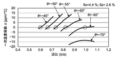
- the side ratio (b / a) with respect to various rotation angles ⁇ that is, cutting orientations when cutting the rotating Y plate for constituting the quartz plate 31 is set.
- the change of the first-order temperature coefficient ⁇ at 25 ° C. in the frequency temperature characteristic when changed was obtained by simulation.
- the results are shown in FIG.
- the portion surrounded by a broken-line circle indicates that the primary temperature coefficient ⁇ is almost zero.
- the rotation angle ⁇ is in the range of ⁇ 70 ° to ⁇ 50 °
- the side ratio (b / a) is in the range of 0.60 to 0.98
- the primary temperature coefficient ⁇ is near room temperature. It is almost zero.
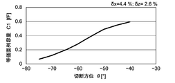
- FIG. 10 is a graph showing the relationship between the rotation angle ⁇ and the equivalent series capacitance C1.
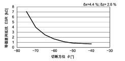
- FIG. 11 is a graph showing the relationship between the rotation angle ⁇ and the equivalent series resistance ESR.
- the rotation angle ⁇ decreases, the equivalent series capacitance C1 decreases and the equivalent series resistance ESR increases.
- the rotation angle ⁇ is smaller than ⁇ 65 °, the equivalent series resistance ESR increases rapidly. Therefore, when considering commercialization, the rotation angle ⁇ should be in the range of ⁇ 65 ° to ⁇ 50 °, and the side ratio (b / a) of the quartz plate should be in the range of 0.65 to 0.98. Is desirable.
- the resonance frequency is determined by the outer shape of the crystal plate. Even if the excitation electrode is formed as wide as possible with respect to the plate surface of the quartz plate, the equivalent series capacitance C1 is reduced and the equivalent series resistance ESR is increased to, for example, about 1 k ⁇ . Since the resonance frequency is determined by the outer shape, it is not possible to adopt a method of increasing the plane size of the quartz plate in order to reduce the equivalent series resistance ESR.
- the crystal resonator according to the present invention Compared to a generally used AT-cut crystal resonator, the crystal resonator according to the present invention has an equivalent series capacitance C1 that is reduced to a fraction, and the equivalent series resistance ESR is several times greater.
- the circuit configuration for achieving stable oscillation becomes complicated.
- the equivalent series resistance of the crystal resonator is large, the oscillation margin of the oscillation circuit decreases.
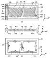
- This crystal resonator includes two crystal plates 41a and 41b having the same crystal orientation and outer shape as the crystal plate 31 described with reference to FIG. 3 in the first embodiment, and is provided in an opening of a frame (frame body) 43.
- the crystal plates 41a and 41b are held.
- the long side of each reference rectangle is parallel to the X ′′ axis and the short side is parallel to the Z ′′ axis. It is indicated by a one-dot chain line in the reference rectangle.
- the two quartz plates 41a and 41b are mechanically coupled to each other by the rod-like connecting member 48 so that their reference rectangles are aligned along the X ′′ axis.
- the quartz plates 41a and 41b are coupled to each other. Since they have the same outer shape, they have the same resonance frequency.
- the crystal plate 41a is supported by mechanically connecting to a rod-like support portion 42a extending along the X ′′ axis direction from the inner wall of the frame 43.
- the crystal plate 41b is also supported from the inner wall of the frame 43 in the X ′′ axis direction. Is supported by being mechanically connected to a rod-like support portion 42b extending along the axis.
- the position where the support portion 42a is connected to the crystal plate 41a is the outer periphery of the crystal plate 41a, and among the four points P 1 to P 4 where the displacement in the X ′′ axis direction is almost 0, P 1 or P 2
- the position where the support portion 42b is connected to the crystal plate 41b is either P 3 or P 4.
- the support portions 42a and 42b are different from the center line passing through the crystal plates 41a and 41b. Since the crystal plates 41a and 41b are mechanically coupled by the connecting member 48, the crystal plates 41a and 41b are supported as a whole by two-point support by the support portions 42a and 42b.
- the thickness of the frame 43 is sufficiently thicker than the thickness of the crystal plates 41a and 41b.
- the extending direction of the support portion can be the Z ′′ axis direction, but in this case, the crystal Position where the support part connects on the plate Is the position of the point on the outer periphery of the quartz plate where the displacement in the Z ′′ axis direction is almost zero.
- connection member 48 is disposed at a position of a center line (line BB ′ in the figure) passing through the crystal plates 41a and 41b.
- the position of the connecting member 48 is not limited to this, but if the positions of the above-mentioned points P 1 to P 4 on the crystal plates 41a and 41b are set, the significance of providing the connecting member 48 is lost, and both quartz crystals The plates 41a and 41b are not mechanically coupled.
- the quartz plates 41a and 41b, the support portions 42a and 42b, the frame 43 and the connection member 48 are integrally formed of quartz.
- a crystal wafer that is a rotating Y plate with a rotation angle ⁇ of ⁇ 65 ° or more and ⁇ 50 ° or less is prepared, and the crystal wafer 41a, 41b, the support portions 42a and 42b, the frame 43, and the connection member 48 can be integrally formed at the same time.
- the two crystal plates 41a and 41b are arranged in a plane stretched by the vibration directions of the two longitudinal vibration modes in the crystal resonator according to the present invention, and the support portion 42 and the connection member 48 are also in this plane. Will be placed.
- the main surface shown on the paper surface in the plan view of the crystal resonator is called the surface of the crystal plate, and is located on the paper back side in the plan view Is called the back side of the crystal plate.
- the front and back surfaces of the frame and the support portion are defined.
- the excitation electrode 51a is formed on almost the entire surface, and the excitation electrode 52a is formed on the almost entire surface of the back surface.
- the excitation electrode 51b is formed on almost the entire surface, and the excitation electrode 52b is formed on almost the entire back surface.
- a pair of connection pads 47a and 47b are provided on the surface of the frame 43 in order to electrically connect the crystal resonator to an external circuit.
- the excitation electrode 51a formed on the surface of the crystal plate 41a is electrically connected to the connection pad 47a via the conductive path 53a formed on the surface of the frame 43 and the support portion 42a.
- the excitation electrode 52a formed on the back surface of the crystal plate 41a is further provided at the end of the conductive path 54a through the frame 43 and the conductive path 54a formed on the back surface of the support portion 42a. It is electrically connected to the connection pad 47b through the hole 46a.
- the excitation electrode 51b formed on the surface of the crystal plate 41b is electrically connected to the connection pad 47b via the conductive path 53b formed on the surface of the frame 43 and the support portion 42b.
- the excitation electrode 52b formed on the back surface of the crystal plate 41b is provided at the end of the conductive path 54b through the frame 43 and the conductive path 54b formed on the back surface of the support portion 42b. It is electrically connected to the connection pad 47a through the hole 46b.
- the conductive paths 54a and 54b correspond to the extraction electrodes in the crystal resonator of the first embodiment.
- the quartz plates 41a and 41b have opposite electrical polarities at the time of excitation.
- the crystal plate 41a extends in the Z ′′ axis direction and contracts in the X ′′ axis direction (in the case indicated by the solid line in the drawing)
- the crystal plate 41b extends in the X ′′ axis direction.
- the crystal plate 41a contracts in the Z ′′ axis direction and extends in the X ′′ axis direction (indicated by a broken line in the drawing)
- the crystal plate 41b contracts in the X ′′ axis direction.
- connection member 48 It extends in the Z ′′ axis direction. Assuming that the two crystal plates 41a and 41b vibrate in this way, the distance between both crystal plates 41a and 41b at the position of the connection member 48 hardly changes, and therefore the connection member 48 is connected to both crystal plates 41a. , 41b are mechanically coupled to each other, but the vibrations in the quartz plates are not hindered.
- both the quartz plates 41a and 41b are provided even when the resonance frequencies of the quartz plates 41a and 41b are slightly shifted from each other. And resonate at the same frequency, and a high Q value can be obtained as a crystal resonator.
- the connection member 48 is not provided, it is electrically equivalent to connecting two crystal resonators whose resonance frequencies are slightly shifted in parallel, and the Q value when viewed as a whole Will drop.
- each crystal plate 41a, 41b is supported by the support portion 42 at the point where the vibration displacement in the X ′′ axis direction or the Z ′′ axis direction on the outer periphery is minimized. 42 does not affect the vibration characteristics of the quartz plates 41a and 41b.
- the connection member 48 mechanically couples the two crystal plates 41a and 41b, the connection member 48 does not inhibit the vibration of the crystal plates 41a and 41b. Since the quartz plates 41a and 41b have the same resonance frequency, the quartz plates 41a and 41b vibrate at the common resonance frequency and are coupled across the quartz plates 41a and 41b even when viewed as a whole crystal resonator. Thus, it vibrates stably in one vibration mode. As a result, this quartz crystal vibrator vibrates extremely stably without causing side vibration.
- the crystal resonator shown in FIG. 12 has the same resonance frequency, but the area of the excitation electrode is doubled, so the equivalent series capacitance C1 is also doubled.
- the equivalent series resistance ESR is halved. Therefore, when the crystal resonator shown in FIG. 12 is applied to an oscillation circuit, the equivalent series resistance is small, so that a large oscillation margin can be achieved with a simple circuit configuration, and a highly stable oscillation circuit can be configured. .
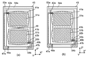
- FIG. 12 shows a crystal resonator according to the second embodiment, which has a configuration in which crystal plates 41a and 41b are mechanically coupled directly.
- connection member 48 is removed from the crystal resonator shown in FIGS. 12A and 12B, and instead of the reference rectangular shape of the crystal plate 41a.
- the outer peripheries of the quartz plates 41a and 41b have a shape in which each side of each reference rectangle is expanded outward except for the sides shared by both the quartz plates 41a and 41b.
- the crystal pieces 41a and 41b have a symmetrical shape with respect to the common side and have the same resonance frequency. Therefore, the crystal resonator shown in FIG. 13 vibrates in the same manner as the crystal resonator shown in FIG. 12, and has twice the equivalent series capacitance C1 and half the equivalent series resistance as compared with the crystal resonator of the first embodiment. Will have ESR.
- quartz resonator In the quartz resonator according to the second embodiment, two quartz plates 41a and 41b whose length in the X ′′ axis direction is longer than the length in the Z ′′ axis direction are arranged in the Z ′′ axis direction to mechanically A quartz crystal unit coupled to is shown.
- the two crystal plates 41a and 41b are mechanically coupled by the connecting member 48 in the same manner as that shown in FIG.
- the crystal plates 41a and 41b are integrated so that the reference rectangles of both the crystal plates 41a and 41b share one side parallel to the X ′′ axis. It shows what was converted.
- the crystal unit is composed of the two crystal plates 41a and 41b.
- three or more crystal plates described with reference to FIG. 3 are used, and three or more crystal plates are used.
- FIGS. 15A and 15B show an example of the crystal resonator of the third embodiment.
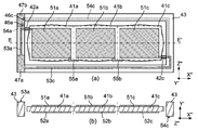
- This crystal resonator is the same as the crystal resonator shown in FIG. 12, but has a structure in which three crystal plates 41a to 41c are connected instead of two. More specifically, in this crystal resonator, three crystal plates 41 a to 41 c having the same crystal orientation and outer shape as the crystal plate 31 described with reference to FIG. 3 in the first embodiment are placed in the opening of the frame 43. It has a retained structure.
- the quartz plates 41a and 41b are mechanically coupled to each other by a connecting member 48a, and the quartz plates 41b and 41c are mechanically coupled to each other by a connecting member 48b.
- the long side of each reference rectangle is parallel to the X ′′ axis and the short side is parallel to the Z ′′ axis.
- the quartz plates 41a to 41c are arranged so that their reference rectangles are aligned along the X ′′ axis. Since the quartz plates 41a to 41c have the same outer shape, they have the same resonance frequency. Yes.
- the crystal plate 41a is mechanically connected to the frame 43 via the support portion 42a
- the crystal plate 41c is mechanically connected to the frame 43 via the support portion 42c. Is held in.
- the positions where the support portions 42a and 42c are connected to the quartz plates 41a and 41c are the outer circumferences of the quartz plates 41a and 41c as in the case of the second embodiment described above, and the displacement in the X ′′ axis direction described above is the same.
- the crystal plates 41a to 41c, the support portions 42a and 42c, the frame 43, and the connection members 48a and 48b are integrally formed of crystal, in the example shown here, the connection member 48a. , 48b are arranged at the position of the center line (DD ′ line in the figure) passing through the quartz plates 41a to 41c.
- excitation electrodes 51a and 52a are formed on almost the entire surface and the back surface of the crystal plate 41a, respectively, and similarly, on the front and back surfaces of the crystal plate 41b, respectively.
- Excitation electrodes 51b and 52b are formed on almost the entire surface
- excitation electrodes 51c and 52c are formed on the almost entire surface on the front and back surfaces of the crystal plate 41c, respectively.
- a pair of connection pads 47a and 47b are provided on the surface of the frame 43 in order to electrically connect the crystal resonator to an external circuit.
- the excitation electrode 51a formed on the surface of the crystal plate 41a is electrically connected to the connection pad 47a via the conductive path 53a formed on the surface of the frame 43 and the support portion 42a.
- the excitation electrode 52a formed on the back surface of the crystal plate 41a is further provided at the end of the conductive path 54a through the frame 43 and the conductive path 54a formed on the back surface of the support portion 42a. It is electrically connected to the connection pad 47b through the hole 46a.
- the excitation electrode 51c formed on the surface of the crystal plate 41c is electrically connected to the connection pad 47a via the conductive path 53c formed on the surface of the frame 43 and the support portion 42c.
- the excitation electrode 52c formed on the back surface of the quartz plate 41c is further provided at the end of the conductive path 54c through the frame 43 and the conductive path 54c formed on the back surface of the support portion 42c. It is electrically connected to the connection pad 47b through the hole 46c.
- the crystal plates 41a and 41c are connected to the support portions 41a and 41c, so that the electrodes can be drawn out through the conductive paths formed in the support portions 41a and 41c.
- the support portion is not connected to the crystal plate 41b sandwiched between the crystal plates 41a and 41c, the electrode cannot be drawn from the crystal plate 41b as it is. Therefore, in the crystal resonator shown in FIG. 15, a conductive path 55a passing through the surface of the connecting member 48a between the crystal plates 41a and 41b is provided, and the excitation electrode 52b on the back surface of the crystal plate 41b is connected to the crystal plate 41a by the conductive path 55a. It is connected to the excitation electrode 51a on the surface.
- the excitation electrode 51b on the surface of the crystal plate 41b is connected to the excitation electrode 52c on the back surface of the crystal plate 41c by a conductive path 55b provided on the surface of the connection member 48b between the crystal plates 41b and 41c.
- the excitation electrodes 51a, 52b, and 51c are electrically connected to the connection pad 47a
- the excitation electrodes 52a, 51b, and 52c are electrically connected to the connection pad 47b.
- the quartz plates 41a and 41b have opposite polarities when excited, and the quartz plates 41b and 41c also have opposite polarities.
- the quartz plates 41a and 41c have the same polarity.
- the crystal plates 41a to 41c vibrate at a common resonance frequency, and even when viewed as a whole crystal unit, the crystal plates 41a to 41c stably vibrate in one vibration mode coupled across the crystal plates 41a to 41c. Will do.
- the area of the excitation electrode is tripled while the resonance frequency is the same, so the equivalent series capacitance C1 is also tripled.
- the equivalent series resistance ESR becomes one third.
- the crystal resonator based on the third embodiment is not limited to the one shown in FIG.
- the crystal resonators shown in FIGS. 16A and 16B are the same as those shown in FIGS. 15A and 15B, but the crystal plates 41a to 41c are directly attached without using connection members. It is constructed by joining.
- the right side of the reference rectangle of the crystal plate 41a and the left side of the reference rectangle of the crystal plate 41b are in contact with each other, and the right side of the reference rectangle of the crystal plate 41 and the left side of the reference rectangle of the crystal plate 41c are mutually connected.
- Three crystal plates 41a to 41c are integrated so as to be in contact with each other.
- the quartz plates 41a to 41c are arranged along the X ′′ axis direction.
- the outer circumferences of the quartz plates 41a to 41c are the sides of each reference rectangle except for the sides shared by other reference rectangles.
- the shape is inflated outward.
- the quartz plates 41a and 41c located at the ends of the integrally formed quartz resonator and the quartz plate 41b located in the middle have a slight difference in resonance frequency when the dimensions of the reference rectangle are the same. there is a possibility. Therefore, for the purpose of matching the resonance frequency, the bulge of the outer peripheral side of the quartz plate 41b may be made different from that of other quartz plates.
- the conductive path 55a that electrically connects the excitation electrode 51a of the crystal plate 41a and the excitation electrode 52b of the crystal plate 41b is provided between the crystal plates 41a and 41b. It is formed on the side surfaces of the crystal plates 41a and 41b so as to straddle the coupling portion.
- a conductive path 55b that electrically connects the excitation electrode 51b of the crystal plate 41b and the excitation electrode 52c of the crystal plate 41c is formed on the side surface of the crystal plates 41b and 41c so as to straddle the coupling portion of the crystal plates 41b and 41c.
- the crystal resonator shown in FIG. 16 also vibrates in the same manner as the crystal resonator shown in FIG. 15, and is equivalent to three times the equivalent series capacitance C1 and one-third equivalent series as compared with the crystal resonator of the first embodiment. It will have resistance ESR.
- 17 (a) and 17 (b) respectively show X ′′ axial directions in the planes of the quartz plates 41a to 41c when the quartz crystal resonator shown in FIG. 16 vibrates in the width / length longitudinally coupled vibration mode.
- required the distribution of the amount of displacement, and the distribution of the amount of displacement of a Z "axial direction by simulation is shown.
- a positive displacement amount indicates a displacement in the positive direction of each axis
- a negative displacement amount indicates a displacement in the negative direction.
- the influence of holding by the support portion is not considered.
- the quartz plate 41a there are two points on the outer periphery that is in the vicinity of the apex on the left edge side in the figure, and the displacement in the X ′′ axis direction is substantially 0. There are two points where the displacement in the X ′′ axis direction is almost zero on the outer periphery near the vertex on the side. At these points, the displacement in the Z ′′ axis direction is also relatively small. Therefore, by connecting a thin rod-shaped support portion to some of these points, the vibration characteristics are not adversely affected. It can be seen that the entire quartz plates 41a to 41c can be supported.
- FIGS. 15 and 16 three crystal plates 41a to 41c whose length in the X ′′ axis direction is longer than the length in the Z ′′ axis direction are mechanically arranged in the X ′′ axis direction.
- the elastic modulus C ′ 11 in the X ′′ axial direction and the elastic modulus C ′ 33 in the Z ′′ axial direction are both the same.
- quartz resonator In the quartz resonator according to the third embodiment, three quartz plates 41a to 41c whose length in the X ′′ axis direction is longer than the length in the Z ′′ axis direction are arranged in the Z ′′ axis direction to mechanically A quartz crystal unit coupled to is shown.
- the three crystal plates 41a to 41c are mechanically coupled by the connection members 48a and 48b in the same manner as that shown in FIG.
- FIG. 18 (b) is a structure in which three crystal plates 41a to 41c are directly coupled as shown in FIG. 16, but the arrangement direction of the crystal plates 41a to 41c is the Z ′′ axis. Is different from that shown in FIG.
- the quartz crystal unit according to the present invention which is a quartz crystal plate mechanically coupled with three quartz plates having substantially the same resonance frequency.
- the number is not limited to three.
- four or more quartz plates are arranged along the X ′′ axis direction or the Z ′′ axis direction and mechanically coupled, and excitation electrodes are connected so that the adjacent quartz plates are excited with opposite polarity.
- By setting the conductive path it is possible to configure a crystal resonator having a larger equivalent series capacitance C1 and a smaller equivalent series resistance ESR.
Landscapes
- Physics & Mathematics (AREA)
- Acoustics & Sound (AREA)
- Piezo-Electric Or Mechanical Vibrators, Or Delay Or Filter Circuits (AREA)
Abstract
L'invention aborde le problème de la réalisation d'un oscillateur à quartz qui peut être fixé avec une pièce formant support de petite taille et à structure simple sans affecter négativement une caractéristique d'oscillation, et qui présente une excellente caractéristique fréquence/température avec un haut degré de souplesse de conception. Selon l'invention, les axes cristallographiques X, Y et Z d'un cristal sont mis en rotation de -65° à -50° autour de l'axe X et sont respectivement définis comme axe X', axe Y' et axe Z', et l'axe X' ainsi que l'axe Z' sont mis en rotation de 40° à 50° autour de l'axe Y' et sont respectivement définis comme axe X" et axe Z". En se référant à un rectangle de référence, lequel est un rectangle ayant des côtés parallèles à l'axe X" et à l'axe Z", l'oscillateur à quartz utilise une plaque de cristal (31) qui présente une forme obtenue par l'expansion d'au moins une paire de côtés opposés du rectangle de référence vers l'extérieur du rectangle de référence, et qui possède des modes d'oscillation longitudinale dans la direction X" et la direction Z".
Applications Claiming Priority (4)
| Application Number | Priority Date | Filing Date | Title |
|---|---|---|---|
| JP2014211563 | 2014-10-16 | ||
| JP2014-211563 | 2014-10-16 | ||
| JP2015-193165 | 2015-09-30 | ||
| JP2015193165A JP2016082584A (ja) | 2014-10-16 | 2015-09-30 | 水晶振動子 |
Publications (1)
| Publication Number | Publication Date |
|---|---|
| WO2016060204A1 true WO2016060204A1 (fr) | 2016-04-21 |
Family
ID=55746744
Family Applications (1)
| Application Number | Title | Priority Date | Filing Date |
|---|---|---|---|
| PCT/JP2015/079171 Ceased WO2016060204A1 (fr) | 2014-10-16 | 2015-10-15 | Oscillateur à quartz |
Country Status (1)
| Country | Link |
|---|---|
| WO (1) | WO2016060204A1 (fr) |
Citations (3)
| Publication number | Priority date | Publication date | Assignee | Title |
|---|---|---|---|---|
| JPS55149519A (en) * | 1979-05-11 | 1980-11-20 | Matsushima Kogyo Co Ltd | Crystal resonator |
| JPS5662404A (en) * | 1979-10-26 | 1981-05-28 | Seiko Instr & Electronics Ltd | Quartz oscillating system |
| JP2012175520A (ja) * | 2011-02-23 | 2012-09-10 | Nippon Dempa Kogyo Co Ltd | 水晶振動子 |
-
2015
- 2015-10-15 WO PCT/JP2015/079171 patent/WO2016060204A1/fr not_active Ceased
Patent Citations (3)
| Publication number | Priority date | Publication date | Assignee | Title |
|---|---|---|---|---|
| JPS55149519A (en) * | 1979-05-11 | 1980-11-20 | Matsushima Kogyo Co Ltd | Crystal resonator |
| JPS5662404A (en) * | 1979-10-26 | 1981-05-28 | Seiko Instr & Electronics Ltd | Quartz oscillating system |
| JP2012175520A (ja) * | 2011-02-23 | 2012-09-10 | Nippon Dempa Kogyo Co Ltd | 水晶振動子 |
Similar Documents
| Publication | Publication Date | Title |
|---|---|---|
| JP6338367B2 (ja) | 水晶振動子 | |
| KR101966126B1 (ko) | 수정 진동판, 및 수정 진동 디바이스 | |
| US7863802B2 (en) | Quartz crystal element made of double-rotation Y-cut quartz crystal plate | |
| US8957569B2 (en) | GT-cut quartz crystal resonator | |
| JP2009147590A (ja) | 水晶振動子片 | |
| JP6719313B2 (ja) | 圧電振動片および圧電振動子 | |
| JP2002158559A (ja) | ラーメモード水晶振動子 | |
| JP5988125B1 (ja) | 水晶振動子及び水晶振動デバイス | |
| JP6948604B2 (ja) | 抑制されたスプリアスモードを伴うmems共振子 | |
| JP5789485B2 (ja) | 水晶振動子 | |
| WO2016060204A1 (fr) | Oscillateur à quartz | |
| JP2016082584A (ja) | 水晶振動子 | |
| JP5661506B2 (ja) | 水晶振動子 | |
| JP6525821B2 (ja) | 音叉型水晶素子 | |
| JP6238639B2 (ja) | 圧電振動子 | |
| JP6573462B2 (ja) | 水晶振動子 | |
| JP2006311303A (ja) | モード結合型圧電振動子 | |
| JP2014030111A (ja) | 水晶フィルタ | |
| JP2016100758A (ja) | 水晶振動子 | |
| JP2007104431A (ja) | 圧電振動子 | |
| WO2016181882A1 (fr) | Élément de vibrations à quartz, et résonateur à quartz | |
| JPH08195643A (ja) | Atカット水晶振動子 | |
| JP2017098911A (ja) | 音叉型水晶素子 |
Legal Events
| Date | Code | Title | Description |
|---|---|---|---|
| 121 | Ep: the epo has been informed by wipo that ep was designated in this application |
Ref document number: 15850545 Country of ref document: EP Kind code of ref document: A1 |
|
| NENP | Non-entry into the national phase |
Ref country code: DE |
|
| 122 | Ep: pct application non-entry in european phase |
Ref document number: 15850545 Country of ref document: EP Kind code of ref document: A1 |