EP2053149A2 - Dispositif jacquard pour déplacer sélectivement des guide-fils dans une machine textile - Google Patents
Dispositif jacquard pour déplacer sélectivement des guide-fils dans une machine textile Download PDFInfo
- Publication number
- EP2053149A2 EP2053149A2 EP08165360A EP08165360A EP2053149A2 EP 2053149 A2 EP2053149 A2 EP 2053149A2 EP 08165360 A EP08165360 A EP 08165360A EP 08165360 A EP08165360 A EP 08165360A EP 2053149 A2 EP2053149 A2 EP 2053149A2
- Authority
- EP
- European Patent Office
- Prior art keywords
- thread
- guide
- guides
- actuating
- apt
- Prior art date
- Legal status (The legal status is an assumption and is not a legal conclusion. Google has not performed a legal analysis and makes no representation as to the accuracy of the status listed.)
- Granted
Links
Images





Classifications
-
- D—TEXTILES; PAPER
- D04—BRAIDING; LACE-MAKING; KNITTING; TRIMMINGS; NON-WOVEN FABRICS
- D04B—KNITTING
- D04B27/00—Details of, or auxiliary devices incorporated in, warp knitting machines, restricted to machines of this kind
- D04B27/10—Devices for supplying, feeding, or guiding threads to needles
- D04B27/24—Thread guide bar assemblies
- D04B27/32—Thread guide bar assemblies with independently-movable thread guides controlled by Jacquard mechanisms
-
- D—TEXTILES; PAPER
- D04—BRAIDING; LACE-MAKING; KNITTING; TRIMMINGS; NON-WOVEN FABRICS
- D04B—KNITTING
- D04B27/00—Details of, or auxiliary devices incorporated in, warp knitting machines, restricted to machines of this kind
- D04B27/02—Warp-thread guides
-
- D—TEXTILES; PAPER
- D04—BRAIDING; LACE-MAKING; KNITTING; TRIMMINGS; NON-WOVEN FABRICS
- D04B—KNITTING
- D04B27/00—Details of, or auxiliary devices incorporated in, warp knitting machines, restricted to machines of this kind
- D04B27/10—Devices for supplying, feeding, or guiding threads to needles
- D04B27/24—Thread guide bar assemblies
Definitions
- the present invention relates to a jacquard device for selectively shifting thread-guides in a knitting machine, in particular for linear knitting machines such as warp looms, e.g. of Raschel type and similar, for obtaining variously knitted fabrics such as jacquard fabrics and the like.
- Selectively shifting thread-guides means shifting them singularly of a space between two adjacent needles, so that during weaving the thread designed for a needle by the movement of the thread-guide bar can be selectively shifted onto the adjacent needle (i.e. forward or backward of one step with respect to the designed position), so as to obtain the desired textile effect.
- the technique involving thread-guide shift by means of piezoelectric actuators is concerned, reference can be made for instance to Patent no. JP63092762 of September 30th 1986 , wherein the selective action is obtained by way of suitably polarized electric current, which is able to deflect a thread-holding plate or thread-guide to the desired position.
- Piezoelectric systems are mainly suitable for use on looms having quite a high needle thickness or fineness.
- fineness refers to the number of needles, and thus of thread-guides, that are present in one inch, i.e. 25.4 mm.
- fineness 24 means that in 1" (one inch), i.e. 25.4 mm, there are 24 needles.
- Needles having such fineness have a hook with a thickness of 0.25 to 0.35 mm and thread-guides that have to get through between one needle and the other safely have approximately the same thickness.
- the shift of the lower portion of the guide holding the thread is of 1.0583 mm, since said guide can shift in a space between two stopping wings or mechanical abutments, and depending on whether it is shifted to the left or to the right, it abuts with its left or right face.
- the piezoelectric actuator in se is very fast in bending for causing the shift of the lower portion of the thread-guide to which it is connected.
- the knitting thread is threaded into the thread-guide, which thread is in se tightened with a force of about 10 grams and more in vertical direction and it is wound or taken by the needle under speed during weaving.
- the thread threaded into the thread-guide is subject to various forces tending to keep the latter in different positions or to let it take such positions.
- the action of the needle on the thread threaded into the yarn is very fast and resembles a pull.
- fineness is lowered, e.g. fineness 14, the distance between two adjacent needles or shed becomes 1.8143 mm.
- the path to go on becomes longer, the time required becomes longer, voltage and current which the actuator has to be supplied with increase, since the latter has to bend more with the same length of the thread-guide and shifting pivot.
- the weight of the thread-guide increases (it is thicker), the count of the yarn used increases (thicker yarn), the forces to be overcome increase due to the thicker yarn, and therefore the actuator can no longer perform its task adequately since the force it can applied is not sufficient to overcome the various forces involved for keeping the thread-guide in the desired position.
- This movement is made up of shifts to the left and to the right of the thread-guide bars, which movements fall within the space of at least one needle shed for Raschel jacquard looms.
- these movements can be very fast (in terms of shots per minute, i.e. to and fro) since they are obtained by way of some mechanical systems that can reach speeds above 3.000 to-and-fros per minute.
- acceleration values achieved by the thread-guide bar are often such as to overcome the force keeping the thread-guide fastened to the mechanical abutment. This occurs when the shifting direction of the bar corresponds to the contact thread-guide/abutments, i.e. thread-guide abutting for instance onto the left stop and bar shifting to the left.
- Shots per minute are those of the needle bars operating synchronously with the thread-guide bars.
- the second known system for selectively shifting thread-guides makes use of elements adjacent to the thread-guides, which are suitably pulled and pushed so as to be able to place the thread-guide in a stable position against one abutment or the other (see documents US4570462 and US3834193 ).
- the most known jacquard heads of this type are "VERDOL ® ", applied first to healds looms and then also to Raschel looms (see for instance US4702286 ), which are able to develop high forces (kilos for pull and tens of hectograms in push, depending on the type of spring applied) and thus to firmly secure the thread-guide in the desired position, avoiding the risk that said thread-guide is deviated or detached from the assigned abutment and thus ensuring accuracy also for swift movements.
- Jacquard heads as was said above, beyond being complex and very expensive, are quite bulky and are typically applied in elevated position above the machine, above the thread-holding rollers, and are characterized by large cord bundles starting from the jacquard head up to the fastenings of the elements for shifting the thread-guides.
- Thread-guides have projections (shaped as folds) interacting with the projections of the shifting elements controlled by the Jacquard mechanical head, which move up and down so as to carry out their task.
- the positioning of the various elements in narrow spaces such as those designed for the shift of the thread-guides between two adjacent needles creates many problems both during construction and during knitting and maintenance operations.
- the protection of the threads so that they do not get in contact with the thread-guides consists in a housing developing on the whole length of the body of the piezoceramic actuator, wholly covering the latter in its front portion.
- Said housing has in its upper portion a projection acting as guide edge for all threads coming from above, determining the trajectory of said threads between the upper contact of the projection and the lower contact of the housing. Since there is no space for screws for securing said housing in the lower area near the hole of the thread-guide, so that it keeps its position without vibrations, a profile (projection) was obtained in the upper portion, designed to delimit the thread trajectory but especially acting as spring tie rod for preventing housing detachment.
- the two contact points of the thread in its operating trajectory lie both on the body of the piezoceramic actuator assembly.
- the present invention aims at solving the problems of the prior art by proposing a jacquard device for selectively shifting thread-guides in a knitting machine, which is free from the described drawbacks.
- a particular aim of the present invention is to disclose a selection system combining the advantages of the two different known technologies described above, solving the problems that prevented up to now their combined used due to their different mechanical-textile features.
- a further aim of the present invention is to provide a system for selectively controlling the shift of the thread-guides, which is able to operate safely at high speeds with a very broad range of different finenesses, developing a sufficient force for moving the thread-guide shifting elements from long distances for this type of applications, preventing at the same time the occurrence of phenomena involving the detachment and bouncing of the thread-guide from its abutment, which affect systems making use of piezoelectric plates.
- Another aim of the present invention is to propose a control device for thread-guide bars of linear knitting machines, which is highly accurate and reliable, and wherein the clearances between the various components are minimized, thus enabling to obtain high-quality finished items.
- a further aim of the present invention is to mitigate the hard working conditions often occurring in the textile field, particularly in the case of jacquard mechanical heads as described above, giving rise to ergonomically more favorable conditions and highly simplifying work for operators working in this field, creating sufficient space for threading operations and simplifying maintenance operation in case of failure or malfunction.
- Another aim of the present invention is to propose a jacquard device for selectively shifting thread-guides in a knitting machine, which is simple to carry out and not very expensive both as far as construction and operation as well as maintenance are concerned, and which further has a robust and compact structure.
- a further aim of the present invention is to provide a device enabling to prevent threads from getting into the seats housing the thread-guides in a movable manner, which has a simpler, less bulky, cheap and technically more functional construction than known solutions.
- a final aim of the invention is to provide a device provided with a pneumatic connection system ensuring a firm positioning of the thread-guide also in case of very small size, such as high finenesses e.g. fineness 24.
- a jacquard device 1 for selectively shifting thread-guides 2 in a knitting machine comprises at least one supporting element 3 provided with a plurality of housing seats 4 for a plurality of thread-guides 2.
- the supporting element 3 can comprise an upper portion 3a ( Fig. 5 ) (further divided into other sub-portions), at least one intermediate portion 3b and a lower portion 3c ( Fig. 6 and 6A ).
- the supporting element 3 is jacquard-type thread-guide bar for a warp linear knitting machine and is movable (in accordance with known technique at least with usual SWING and SHOG movements) with respect to at least one bed 5 of needles 6 for selectively feeding a thread 7 to the needles of said needle bed.
- the machine of the example disclosed here (not shown as a whole since it is of known type) is equipped with two jacquard devices for each bed 5, 5a of needles 6, since on a first device 1 there are only odd thread-guides apt to operate on odd needles of the needle bed, and on the second device 1 there are only even thread-guides apt to operate on even needles of the needle bed.
- the machine according to the present embodiment is equipped with two needle beds 5, 5a and with eight thread-guide bars, four with conventional fixed thread-guides and four with moving or jacquard thread-guides according to the invention.
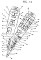
- Figure 1 shows for simplicity's sake only the four bars on the right of a bar-holding support 8, which operate on the first needle bed 5, whereas the other four bars on the left apt to operate on the second needle bed 5a and symmetrical with respect to the first four are not shown.
- the two outer bars 9 are of conventional type with fixed thread-guides, whereas the middle bars are of the type with jacquard moving thread-guides according to the present invention.
- the device 1 comprises a plurality of thread-guides 2 having each at least one mounting seat 2a on which they are mounted onto the supporting element 3 by way of a further mounting element 3d, and at least one pierced thread-guide portion 2b selectively moving between a first and second operating position and apt to guide a thread 7.
- Each housing seat 4 of the lower portion 3c of the supporting element 3 is equipped with side end-of-stroke portions or stops 10 apt to determine the first and the second operating position of the thread-guide portion 2b of the thread-guide 2 mounted in said housing seat 4.
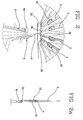
- Figure 2A shows the two positions of a thread-guide 2 with respect to a needle 6, the position in which it is beside the left stop 10 and therefore is placed on the left of a needle 6, and the other position (in which the thread-guide 2 is represented only partially) in which it is beside the right stop 10 and therefore is placed on the right of a needle 6.
- each thread-guide further comprises an actuating portion 2c on which an engagement element 11 is located, and a guide portion 2d pierced and apt to cooperate with an elongated guide element 46 (which can be seen in Figure 6b ) getting through a plurality of thread-guides 2.
- the device 1 further comprises at least one actuating element 12 (see
- the device 1 therefore comprises a plurality of actuating elements 12 or "sliders" each associated to a corresponding thread-guide 2.
- Each actuating element 12 is equipped with a cam-shaped element 13 shown in Figure 11 (shifting cam made up for instance of a plate with an inclined recess) cooperating with the engagement element 11 of the corresponding thread-guide so as to convert the movement of the actuating element 12 into a pre-established movement of the actuating portion of the thread-guide 2 and therefore of the thread-guide portion 2b of the thread-guide.
- a cam-shaped element 13 shown in Figure 11 shifting cam made up for instance of a plate with an inclined recess
- the cam-shaped element 13 is apt to convert the vertical movement of the actuating element 12 inside a suitable operating seat 14 thereof associated to or obtained in the intermediate portion 3b of the supporting element 3, into a side movement (from right to left), and conversely, of the thread-guide portion 2b of the corresponding thread-guide.
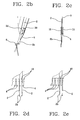
- the actuating elements 12 are arranged spaced apart on at least two rows at different heights, so that the actuating devices 12 connected to adjacent thread-guides are arranged on different rows, and in particular in the preferred embodiment they are arranged at three heights (as shown in Figures 3 , 4 , 7, 8, 8A, 8B ). As will be explained in detail later, this enables to observe the small distances between one thread-guide 2 and the other, in case of high finenesses, even though the actuating devices 12 are excessively bulky.
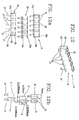
- the device 1 further comprises at least one electropneumatic actuating device 15 ( Figures 12 and 13 ) operatively connected to each actuating element 12 so as to move the actuating element 12, and therefore the thread-guide portion 2b of the corresponding thread-guide between the first and the second operating position.
- the device 1 therefore comprises a plurality of electropneumatic actuating devices 15 each operatively connected to a corresponding actuating element 12.
- the electropneumatic actuating device 15 further comprises at least one pneumatic device 16 having a moving element (or piston ) 17 connected to the actuating element 12 ( Figure 8 ), which can be selectively shifted between a forward and a backward position.
- the pneumatic device 16 comprises a housing body (or "case") 18 in which at least one sliding seat 19 is located, which houses movingly the moving element 17, thus constituting a pneumatic piston.
- the housing body 18 is provided on the sliding seat 19 with at least one main opening 20 apt to enable the passage of the moving element 17 and the movement thereof between the forward and the backward position (see Figures 12 and 12A ).
- the housing body 18 is further provided on the sliding seat 19 with at least a first air opening 21 (two holes for instance) and with at least a second air opening 22 (two holes for instance), the first opening 21 being apt to enable the introduction of compressed air P (for instance at a pressure of about 0.55 MPa) into a first portion 19a of the sliding seat 19 so as to push the moving element to its forward position, whereas the second opening 22 is apt to enable the introduction of compressed air Pa in counter-pressure (for instance at a pressure of about 0.35 MPa) into a second portion 19b of the sliding seat 19 so as to push the moving element 17 to its backward position.
- first air opening 21 two holes for instance
- second air opening 22 two holes for instance
- the moving element 17 is provided with at least one pushing portion 17a on the second portion 19b of the sliding seat 19 so as to enable compressed air getting in from the second opening 22 to push the moving element 17 to its backward position.
- each housing body 18 is equipped with a plurality of seats 19 for housing a plurality of moving elements 17, and in the preferred embodiment shown here each housing body 18 is provided with five sliding seats in which the same number of moving elements 17 shifts ( Figures 12 and 12A ).
- the moving elements 17 of the pneumatic devices 16 are placed spaced apart on at least two rows at different heights, and in particular at three heights, so that moving elements 17 connected to adjacent thread-guides 2, by way of corresponding actuating devices 12, are arranged on different rows. This enables to observe the small distances between one thread-guide and the other even though the pneumatic devices are bulkier, in case of high finenesses.
- the electropneumatic actuating device 15 further comprises at least one electropneumatic valve (or solenoid valve) 23, shown in detail in Figures 13 and 13A , operatively connected, preferably by way of air pipes 33 and air ducts obtained in the supporting element 3, to a pneumatic device 16 so as to selectively shift the moving element 17 supplying said pneumatic device 16 with compressed air.
- electropneumatic valve or solenoid valve
- the device 15 comprises an electropneumatic valve 23 connected to each pneumatic device 16, and in particular an electropneumatic valve 23 for each moving element 17.
- Each electropneumatic valve 23 is equipped with at least one valve body 24 for air communicating with the outer environment by means of an air inlet opening 25, an air outlet opening 26, operatively connected to the corresponding pneumatic device 16 on the first opening 21 thereof, and an exhaust opening 27 for evacuating air into the environment.
- the device 1 further comprises a pneumatic supply system 28 comprising a main pneumatic supply system 28a (or main pneumatic bus) apt to supply each electropneumatic valve 23 with inlet compressed air P, connected in particular to the corresponding air inlet openings 25 of each electropneumatic valve.
- a pneumatic supply system 28 comprising a main pneumatic supply system 28a (or main pneumatic bus) apt to supply each electropneumatic valve 23 with inlet compressed air P, connected in particular to the corresponding air inlet openings 25 of each electropneumatic valve.
- the pneumatic supply system 28 further comprises a counter-pressure pneumatic supply system 28b (or counter-pressure bus) operatively connected directly to each pneumatic device 16 on said second openings 22 thereof so as to enable the introduction of compressed air Pa into said second portions 19b of the sliding seats 19 and to push each moving element 17 to its backward position when the corresponding electropneumatic valve 23 is able to evacuate air from the exhaust opening 27.
- a counter-pressure pneumatic supply system 28b (or counter-pressure bus) operatively connected directly to each pneumatic device 16 on said second openings 22 thereof so as to enable the introduction of compressed air Pa into said second portions 19b of the sliding seats 19 and to push each moving element 17 to its backward position when the corresponding electropneumatic valve 23 is able to evacuate air from the exhaust opening 27.
- the counter-pressure pneumatic supply system 28a further comprises a pressure reducing device 29 operatively arranged upstream from the second opening 22 of the pneumatic system 16 so as to supply said pneumatic devices 16 with a reduced pressure or counter-pressure Pa.
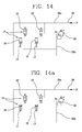
- the supply system 28 is schematically shown in Figures 14 and 14A , in which the inlet of pressurized air P supplying the inlet of the electropneumatic valves 23 can be seen, which valves are in their turn connected to the pneumatic devices 16. Moreover, the pressure reducer 29 can be seen, from which air Pa is sent to the second opening 22 for compressed air of the pneumatic devices 16 so as to act as a "pneumatic spring" which is always active, no matter if the solenoid valves 23 are activated or not.
- Figure 14 shows the first operating condition in which the two electropneumatic valves 23 supply the corresponding pneumatic devices 16 with pressurized compressed air P, causing the shift of the moving elements 17 to their forward position
- Figure 14a shows a second operating condition in which the two electropneumatic valves 23 do not supply with compressed air P the pneumatic devices 16 (closing the inlet opening 25 for compressed air in said solenoid valves) and are in exhaust position in which air is evacuated into the outer environment (the outlet opening 26 and the exhaust opening 17 are open), so that compressed air at lower pressure Pa supplied by the pressure reducer 29 to said pneumatic devices 16 causes the shift of the moving elements 17 to their backward position and the return of air to be evacuated to the electropneumatic valves 23.
- the device 1 further comprises an electric supply system or electric bus 45 ( Fig. 3-5a ) for supplying the solenoid valves 23.
- the electric supply system 45 further comprises a plurality of control devices 47 for the solenoid valves 23, e.g. electronic control cards, which are not described in detail since of per se known type, operatively connected to the electropneumatic valves 23 so as to control the movement of the thread-guide portions 2b of the thread-guides 2 in accordance with a pre-established jacquard operating program, and further connected (for instance by way of said electric bus 45) to a control device for the device 1 and thus to control means for the machine (both are not shown or described in detail since of per se known type).
- control devices 47 for the solenoid valves 23 e.g. electronic control cards, which are not described in detail since of per se known type, operatively connected to the electropneumatic valves 23 so as to control the movement of the thread-guide portions 2b of the thread-guides 2 in accordance with a pre-established jacquard operating program, and further connected (for instance by way of said electric bus 45) to a control device for the device 1 and thus to control
- the device 1 further comprises at least a covering element 30, made up for instance of a metal sheath, apt to cover at least one portion of said housing seats 4 of the supporting element 3 for supporting the threads 7 inserted into the thread-guides 2, guiding the sliding of said threads 7 and prevent said threads 7 from getting into the housing seats and from interfering with the movement of the thread-guides 2.
- a covering element 30, made up for instance of a metal sheath apt to cover at least one portion of said housing seats 4 of the supporting element 3 for supporting the threads 7 inserted into the thread-guides 2, guiding the sliding of said threads 7 and prevent said threads 7 from getting into the housing seats and from interfering with the movement of the thread-guides 2.
- the covering element is mounted onto the supporting element 3 (onto the lower portion 3c thereof) near the side end-of-stroke portions or stops 10 so as to cover at the same time a plurality of housing seats 4 for the thread-guides 2, and it is advantageously fitted onto corresponding engagement seats 31 obtained on said supporting element 3.
- the metal sheath 30 is advantageously inserted into the lower portion 3c of the housing (the supporting element 3) for the thread-guides 2 in the supporting element 3, and the engagement seats 31 on the housing are suitably shaped so as to preload the sheath 30, so that said sheath 30 can then be taken off and repositioned without using glue or screws.
- the sheath 30 is pressed in and prevents the thread 7 from getting into the housing seats 4 in which operate the thread-guides 2, and acts at the same time as safe guide for said threads 7.
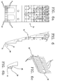
- the sheath 30 is as long as a housing (shown in Figure 6A ) of the supporting element 3 and, when it is mounted and the housings lie close to one another, it leaves no space to the thread 7 for penetrating between one sheath 30 and the other.
- Figure 6C shows the operating condition of the covering element supporting a plurality of threads feeding corresponding thread-guides 2.
- the device 1 further comprises an additional supporting element 32 for the thread, for instance a metal wire, arranged upstream from the covering element 30 with respect to the feeding path of the thread 7 and basically near the upper portion of the thread-guide bars 3.
- an additional supporting element 32 for the thread for instance a metal wire, arranged upstream from the covering element 30 with respect to the feeding path of the thread 7 and basically near the upper portion of the thread-guide bars 3.
- said additional supporting element 32 could also be placed elsewhere, provided that in such position it can adequately support the thread 7 together with the covering element 30.
- the trajectory of the thread 7 preferably has its contact points in two separate areas, one directly on the body of the supporting element 3 (on the metal rod 32 suitably placed), the other one is the one of the small metal sheath 30 lying very close to the hole of the thread-guide portion 2b of the thread-guide 2.
- the covering element 30 according to the invention effectively applies also to non-electropneumatic jacquard devices, and therefore also to piezoelectric, mechanical or other jacquard devices.
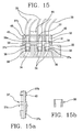
- the device 1 further comprises at least a compressed air pipe (or tube) 33, at least a compressed air passage duct 34 obtained in a body 35 integral with or part of the supporting element 3 and provided with an inlet seat 36, at least one connecting element 37 or barbed fitting (shown in partial section in Figure 15A ), hollow inside and provided with two ends 37a, 37b having an outer surface that is at least partially conical and apt to connect the air pipe 33 to the passage duct 34.
- the device 1 further comprises at least one seal 38 (shown in section in Figure 15B ) apt to be inserted into the inlet seat 36 for compresses air of said body 35 and having an outer round shape and an inner surface that is at least partially conical and apt to fit into a lower end 37a of the connecting element or barbed fitting 37. It should be pointed out that the partially conical inner surface of the seal 38 cooperates effectively with the lower end 37a of the connecting element 37 and ensures a good sealing in the compressed air circuit even in case of very small size.
- the device 1 further comprises a first fastening element 39 apt to keep in position the lower end 37a of the connecting element 37 inside the seat 36 of the air passage duct 34, and at least one second fastening element 40 apt to keep in position the upper end 37b of the connecting element 37 inside the air pipe 33.
- the first fastening element 39 is a plate preferably provided with a plurality of openings 41 apt to house and fasten to body 35 a plurality of connecting elements 37
- the second fastening element 40 is a second plate apt to keep in position a plurality of connecting elements 37 inside a corresponding plurality of air pipes 33.
- the seal 38 is placed in the inlet seat 36 of the compressed air passage duct 34, then the lower end 37a of the connecting element 37 is snap fitted into the seal 38 and then the first fastening element 39 is positioned by inserting the connecting element 37 into a hole 41 of the first fastening element 39, which hole is provided with a relief 39a cooperating with a projection 37c of the connecting element or barbed fitting 37 for keeping it in position in contact with the body 35.
- the barbed fitting 37 is shaped so that the first fastening element 39 can push it downwards.
- the pressure exerted by the plate 39 forces the barbed fitting to get down and to interfere with the seal 38 blocking the latter inside the inlet seat 36 of the body 35 by means of the conical portion, creating a tightness also on the lower end 37a of the barbed fitting 37.
- the compressed air pipe 33 is inserted into a hole 42 of the second fastening element 40, which is slid along the pipe for a certain length beyond the lower end of the compressed air pipe 33.
- the conical upper end 37b of the connecting element 37 is snap fitted into the lower end of the corresponding air pipe 33, then the second fastening element 40 is slid on said lower end of the compressed air pipe 33 so that a protruding portion 43 of the conical upper end 37b of the connecting element 37 deforms the inner surface of the compressed air pipe 33, so that the forced coupling can ensure the tightness of the connection.
- the second fastening element 40 is fastened to the first fastening element 39 so as to make it integral with the body 35 by way of at least one sealing element 44, which can be made up for instance of a screw or other suitable element.
- the air seal 38 and the system described above according to the invention can be used so as to couple the various ducts obtained in the support element 3 with the various compressed air tubes, and therefore said system is used preferably on the large number of pneumatic connections between tubes and ducts that are present in the device 1 for supplying the various elements of the device 1 with compressed air.
- connection system described above ensures a high tightness of the pneumatic connection also with very small elements close to one another, without using traditional O-rings, which would not ensure a sufficient tightness in such a highly miniaturized application.
- Each solenoid valve 23 is supplied with voltage and current by means of the dedicated electric supply system or electric bus 45 extending on the whole supporting element 3 or jacquard bar (for instance, the connection of the solenoid valves to the control device for the device 1 can be advantageously be carried out by using the same electric bus 45).
- Said bar 3 also houses the pneumatic supply system 28 or pneumatic supply bus, which is used by the solenoid valves 23 to fill with pressure P selectively through suitable ducts (pipes + holes) the compartments of the cylinder body 16, so that the moving element 17 can shift in the pre-established direction and get out of the housing body 18.
- the counter-pressure pneumatic supply system 18b or counter-pressure pneumatic bus is made up of the ducts reaching each piston 17 in the lower portion of the housing body 18 so as to supply the necessary counter-pressure Pa (pneumatic spring) causing the piston 17 to get back into its case 18 when the solenoid valve is de-energized and air present in the ducts lying between the solenoid valve 23 and the piston 17 is evacuated (discharged) exactly by the effect of the pneumatic spring, which fills the second portion 19b of the sliding seat 19 causing the moving element 17 to be lifted up and the space previously occupied by pressurized air of the pneumatic supply bus to be emptied. Air is evacuated through the exhaust opening 27 of the solenoid valve 23.
- pressure level is adjusted so that the time spent by the piston for getting out of its case is the same as the time used for getting in, thus forming a balanced control system, since the time in which the thread-guide is shifted in one direction or the other must be the same.
- the cam-shaped element 13 shifts the thread-guide 2 vigorously, since the piston 17 supplies in and out a force of about 350/400 grams (force values which are ten times higher than those of piezoceramic systems).
- the slider 12 can be shifted only in vertical direction, the horizontal movement (right or left) thereof being prevented by the operating seat 14 in which it slides in the body 3, thus generating a very high horizontal force which prevents the thread-guide 2 from moving in that direction even to a very small extent.
- the thread-guide 2 does not move to its position, it may happen that the thread 7 breaks but the slider 12 cannot move horizontally (if the thread is too strong, it may break the thread-guide).
- the detachment of the thread-guide 2 from the mechanical abutment due to the strong SHOG accelerations of the bar cannot occur since the slider, and therefore the thread-guide, cannot move horizontally.
- the invention offers the possibility to freely vary the horizontal shift of the thread-guides (higher stroke, adjustable also to very low finenesses such as 3, 4 or 5), since it is sufficient to use an adequate size for the system varying in particular the shape of the cam 13 (the inclination of the recess of the slider plate).
- the thread-guide 2 is however shifted by the piston 17, which can in its turn be bigger.
- the thread 7 cannot shift horizontally the slider 12, but it can only break as was mentioned above, or break the thread-guide.
- the jacquard bars or devices 1 are independent and carry part of the machine intelligence in the form of drivers for the selective electronic actuation of the solenoid valves 23. Moreover, thanks to the device 1 according to the invention the function of the solenoid valves 23 can be tested.
- a suitable solenoid valve 23 will not be described in detail here since they are of per se known type, and since different sophisticated technologies can be used for said valve.
- each thread-guide 2 should be able to shift from its position (to the right or to the left) of a needle shed, and requires therefore sufficient space.
- the device or bar 1 designed for jacquard knitting should be doubled, thus there are two bars for each needle bed, one for even thread-guides 2 and one for odd thread-bars 2.
- One bar will carry the thread-guides 2 working on even needles, the other one will work on odd needles, but each bar will enable its thread-guides 2 to shift of one needle to the right or to the left in the free space left by the thread-guide absent from its position.
- the thread-guide absent on the bar of even needles will obviously be present on the bar of odd needles.
- thread-guides involved in this operation form knitted fabric also on the opposite needle bed, i.e. thread-guides on the front needle bed receiving a suitable order form knitted fabric not only on their needle bed but also on the rear needle bed, and conversely.
- each pneumatic device 16 is made up of only one housing body or case 18 for each moving element 17.
- the pneumatic pistons 17 (or moving elements) have a diameter of 4 mm and are contained in a housing body or "case" 18 with a width of 5 mm. Therefore, said pistons 17 cannot be placed one beside the other as they would occupy a space of 10 mm, whereas the available space is of 2.1166 mm. Moreover, the sum of the various sheds (depending on fineness) does not result in finite numbers, but values with various tens of different numbers after point.
- the following cases can be placed on the same plane at a finite distance (6.35) from one another.
- the case A will control a first thread-guide
- the case B the following one spaced of the shed of two needles
- the cases C will control a third thread-guide spaced from the first one of 4.2333 mm
- the case A' will control a fourth thread-guide spaced from the first one of 6.35 mm.
- the thread-guides 2 will have as pivot one single point (on the mounting seat 2a), and as actuating portion 2c (or shifting area) three different positions on three different levels (for three following thread-guides 2). If we consider three cases A, B, C as a block, we can state that each block will be spaced apart of 6.35 mm.
- actuating system is of "MONOSTABLE" type with two positions.
- One position (the backward one) is stable when the solenoid valve 23 is de-energized (since the "pneumatic spring” always brings it back to the backward or default position).
- the other position (the forward one) is reached when the solenoid valve 23 is energized and it is kept until the electrical supply ends, which may happen as a result of an OFF control or of a blackout-
- the system is equipped with a suitable no-break power supply or standby battery, which is able to keep energized the solenoid valves 23 that were in ON status when the electrical supply was interrupted, so that the risk of a collision between thread-guide 2 and needle 6 when the machine is operating either SWING or SHOG movements is prevented. Therefore, the solenoid valve 23 is able to keep the single-effect pneumatic piston 17 constantly under pressure and in a pre-established position (through pneumatic counter-pressure or pneumatic spring) also in case of absence of electrical supply.
- the time for which the solenoid valve 23 is kept in ON status should be long enough so that the knitting machine undergoing the flywheel action of its moving elements stops completely in a predefined parking position.
- the solenoid valves 23 can therefore control (by way of uninterruptible power supply or standby battery), thanks to their lower electrical power absorbance, the pneumatic piston 17 connected thereto, keeping the status achieved or changing the latter depending on the program.
- the machine is normally stopped in "ZERO" position at a pre-established angular value of the drive shaft, in which position all maintenance operations can be carried out easily and without interferences. "Zero" position is also the starting position of the control program for the machine.
- piezoelectric or piezoceramic actuators keep the acquired position in case of power interruption and act as capacitors.
- the machine does not stop immediately and due to the flywheel effect due to its heavy transmission elements it goes on for a small space in its movement, so that the control system must record and store the whole machine status when the machine is actually still, so as to be able to resume work from the point where it stopped without damaging the fabric.
- the machine could stop without damage with the thread-guides placed between the needles, and if the stop is due to a thread break, it becomes sometimes quite impossible to repair and knot again the broken thread. It is therefore advisable to push the machine onward for a small space (using no-break power supply as described in the previous case) and park it in a position in which the operations involving the repair of the broken thread are simpler.
- the invention further relates also to a method for selectively shifting thread-guides 2 in a textile machine, comprising at least the step of supplying with compressed air the electropneumatic actuating devices 15, and in particular of supplying with such compressed air the plurality of electropneumatic valves 23 being part of the electropneumatic actuating devices 15, and therefore the plurality of pneumatic devices 16 having each at least one moving element 17 connected to a corresponding actuating element 12.
- the method further comprises the step of providing the electropneumatic actuating devices 15 and in particular the electropneumatic valves 23 with a jacquard movement program, so as to selectively shift by way of the electropneumatic actuating devices 15, supplied with compressed air, the actuating elements 12 in accordance with the jacquard movement program.
- said step is carried out by selectively shifting, by way of the adjustment of the amount of compressed air supplied by the electropneumatic valves 23, the moving elements 17 between the forward and the backward position, in accordance with the jacquard movement program.
- the method further comprises the step of moving by means of the actuating elements 12 the corresponding thread-guide portions 2b of the thread-guides 2, mounted in the housing seats 4 obtained on the supporting element 3, at least between the first and the second operating position.
- the invention achieves important advantages.
- a jacquard device for selectively shifting thread-guides in a knitting machine can apply successfully to a very broad range of finenesses of a knitting machine.
- the invention ensures both a high force for keeping the thread-guides in the desired position also in case of relatively large shifts of the thread-guides (which is required for low finenesses) and a high compactness and speed in actuating the various parts and the thread-guides themselves (which is required for high finenesses).
- the device according to the present invention thus offers a high degree of operating safety also at high speeds and with several finenesses, avoiding the occurrence of phenomena of detachment and bouncing of the thread-guide from the corresponding abutment.
- the device according to the invention is extremely accurate and reliable, reducing maintenance intervals and enabling to obtain finished products of very high quality.
- the invention further enables to improve the operating conditions for people working in the field, since the various parts of the machine are very robust and compact, minimizing maintenance operations and part replacement and providing spaces that are ergonomically sufficient for required interventions such as threading and maintenance operations.
- the invention enables to prevent threads from interfering with thread-guide movement with a solution that is easy to carry out and to assemble, small in size and economical. It should further be pointed out that a device according to the invention has pneumatic connections ensuring high tightness conditions also for extremely miniaturized connections.
- a device according to the invention is very compact, simple to carry out and not very expensive both as far as construction and operation as well as maintenance are concerned.
Landscapes
- Engineering & Computer Science (AREA)
- Textile Engineering (AREA)
- Knitting Machines (AREA)
- Yarns And Mechanical Finishing Of Yarns Or Ropes (AREA)
- Treatment Of Fiber Materials (AREA)
Applications Claiming Priority (1)
| Application Number | Priority Date | Filing Date | Title |
|---|---|---|---|
| IT000164A ITBS20070164A1 (it) | 2007-10-24 | 2007-10-24 | Dispositivo jacquard per lo spostamento selettivo di passette guidafilo in una macchina tessile |
Publications (3)
| Publication Number | Publication Date |
|---|---|
| EP2053149A2 true EP2053149A2 (fr) | 2009-04-29 |
| EP2053149A3 EP2053149A3 (fr) | 2015-07-22 |
| EP2053149B1 EP2053149B1 (fr) | 2016-11-23 |
Family
ID=40313645
Family Applications (1)
| Application Number | Title | Priority Date | Filing Date |
|---|---|---|---|
| EP08165360.2A Not-in-force EP2053149B1 (fr) | 2007-10-24 | 2008-09-29 | Dispositif jacquard pour déplacer sélectivement des guide-fils dans une machine textile |
Country Status (5)
| Country | Link |
|---|---|
| US (1) | US7607324B2 (fr) |
| EP (1) | EP2053149B1 (fr) |
| JP (1) | JP4974032B2 (fr) |
| CN (1) | CN101418494B (fr) |
| IT (1) | ITBS20070164A1 (fr) |
Cited By (3)
| Publication number | Priority date | Publication date | Assignee | Title |
|---|---|---|---|---|
| ITMI20091819A1 (it) * | 2009-10-21 | 2011-04-22 | Comez Gestioni S P A | Macchina tessile elettro-pneumatica |
| CN102733078A (zh) * | 2011-04-08 | 2012-10-17 | 利巴机械制造有限公司 | 拉舍尔经编机 |
| EP3139391A1 (fr) | 2015-09-03 | 2017-03-08 | Baumüller Nürnberg GmbH | Actionneur pour aiguilles textile |
Families Citing this family (16)
| Publication number | Priority date | Publication date | Assignee | Title |
|---|---|---|---|---|
| KR100976929B1 (ko) * | 2008-04-16 | 2010-08-18 | 소진수 | 실공급방법, 경사공급방법, 실공급장치 및 직조방법 |
| IT1391728B1 (it) * | 2008-11-26 | 2012-01-27 | Santoni & C Spa | Attuatore piezoelettrico per barre guidafilo jacquard di macchine tessili |
| IT1391730B1 (it) * | 2008-11-26 | 2012-01-27 | Santoni & C Spa | Dispositivo di connessione per attuatori piezoelettrici di barre jacquard di macchine tessili |
| IT1391729B1 (it) * | 2008-11-26 | 2012-01-27 | Santoni & C Spa | Barra guidafilo jacquard per macchine tessili per maglieria in catena |
| DE102009022191B3 (de) * | 2009-05-20 | 2011-06-16 | Karl Mayer Textilmaschinenfabrik Gmbh | Fadenführeranordnung einer Kettenwirkmaschine |
| ITBS20130089A1 (it) * | 2013-06-21 | 2014-12-22 | Santoni & C Spa | Elemento di erogazione del filo per un guidafilo per macchine tessili, e guidafilo comprendente tale elemento di erogazione |
| ITBS20130086A1 (it) * | 2013-06-21 | 2014-12-22 | Santoni & C Spa | Dispositivo per alimentare filo agli aghi di una macchina tessile |
| DE102014108987B3 (de) * | 2014-06-26 | 2015-10-22 | Karl Mayer Textilmaschinenfabrik Gmbh | Wirkware, Verfahren zum Erzeugen einer Wirkware und Kettenwirkmaschine |
| ES2712737T3 (es) * | 2016-05-04 | 2019-05-14 | Groz Beckert Kg | Módulo de herramienta textil y máquina textil con un módulo de herramienta textil |
| CN106995978B (zh) * | 2017-05-18 | 2022-06-10 | 王占洪 | 贾卡梳地梳混装的多功能梳栉 |
| CN107503039A (zh) * | 2017-08-30 | 2017-12-22 | 信泰(福建)科技有限公司 | 一种满机号电子贾卡梳 |
| US10669658B2 (en) | 2017-12-06 | 2020-06-02 | Pai Lung Machinery Mill Co., Ltd. | Electronic yarn changing device for circular knitting machine |
| ES2776732T3 (es) | 2017-12-11 | 2020-07-31 | Pai Lung Machinery Mill Co Ltd | Dispositivo electrónico de cambio de hilo para máquina de tejer circular |
| TWD207732S (zh) * | 2019-06-12 | 2020-10-11 | 義大利商聖東尼股份公司 | 紡織機組件 |
| TWD208197S (zh) * | 2019-06-18 | 2020-11-11 | 義大利商聖東尼股份公司 | 紡織機構件 |
| TWD208383S (zh) * | 2019-06-18 | 2020-11-21 | 義大利商聖東尼股份公司 | 紡織機構件 |
Citations (5)
| Publication number | Priority date | Publication date | Assignee | Title |
|---|---|---|---|---|
| US3834193A (en) | 1973-04-02 | 1974-09-10 | Mayer Textilmaschf | Process for the production of multi-colored single face ware |
| US4570462A (en) | 1983-06-16 | 1986-02-18 | Karl Mayer Textilmaschinenfabrik Gmbh | Warp knitting machine with Jacquard guides |
| US4702286A (en) | 1985-09-06 | 1987-10-27 | Etablissments Staubli-Verdol | Shed forming devices in weaving looms including pivotable retaining hooks |
| JPS6392762A (ja) | 1986-09-30 | 1988-04-23 | 日本マイヤー株式会社 | 編織機における導糸針の変位装置 |
| US5561989A (en) | 1994-06-18 | 1996-10-08 | Karl Mayer Textilmachinenfabrik Gmbh | Jacquard bar for warp knitting machines |
Family Cites Families (9)
| Publication number | Priority date | Publication date | Assignee | Title |
|---|---|---|---|---|
| US4051698A (en) * | 1975-11-13 | 1977-10-04 | Herbert Leonhardt | Guide bar assembly for a warp knitting machine |
| DE2550921C3 (de) * | 1975-11-13 | 1979-01-04 | Textiel Industrie Andex B.V., Heerlen (Niederlande) | Kettenwirkmaschine mit einzeln steuerbaren Fadenlegern |
| JPH0441736A (ja) * | 1990-06-02 | 1992-02-12 | Murata Mach Ltd | 直動型ジャカード縦針駆動装置 |
| JPH0578961A (ja) * | 1991-01-22 | 1993-03-30 | Rindou Eng:Yugen | 経編機の糸張力装置 |
| JPH07197358A (ja) * | 1993-12-28 | 1995-08-01 | Etsuzou Sasaki | ジャカードガイド及びジャカードガイドユニット |
| US5675993A (en) * | 1994-01-14 | 1997-10-14 | Nippon Mayer Co. Ltd. | Patterning method and device in warp knitting machine |
| DE19514995C2 (de) * | 1995-04-24 | 1997-06-19 | Mayer Textilmaschf | Kettenwirkmaschine |
| DE10066042B4 (de) * | 2000-08-23 | 2004-12-02 | Karl Mayer Textilmaschinenfabrik Gmbh | Kettenwirkmaschine mit mehreren Musterlegebarren |
| WO2002027087A1 (fr) * | 2000-09-27 | 2002-04-04 | Nippon Mayer Ltd. | Dispositif jacquard pour metier a mailles jetees |
-
2007
- 2007-10-24 IT IT000164A patent/ITBS20070164A1/it unknown
-
2008
- 2008-09-29 EP EP08165360.2A patent/EP2053149B1/fr not_active Not-in-force
- 2008-10-22 US US12/256,077 patent/US7607324B2/en not_active Expired - Fee Related
- 2008-10-23 CN CN2008101713693A patent/CN101418494B/zh not_active Expired - Fee Related
- 2008-10-24 JP JP2008274619A patent/JP4974032B2/ja not_active Expired - Fee Related
Patent Citations (5)
| Publication number | Priority date | Publication date | Assignee | Title |
|---|---|---|---|---|
| US3834193A (en) | 1973-04-02 | 1974-09-10 | Mayer Textilmaschf | Process for the production of multi-colored single face ware |
| US4570462A (en) | 1983-06-16 | 1986-02-18 | Karl Mayer Textilmaschinenfabrik Gmbh | Warp knitting machine with Jacquard guides |
| US4702286A (en) | 1985-09-06 | 1987-10-27 | Etablissments Staubli-Verdol | Shed forming devices in weaving looms including pivotable retaining hooks |
| JPS6392762A (ja) | 1986-09-30 | 1988-04-23 | 日本マイヤー株式会社 | 編織機における導糸針の変位装置 |
| US5561989A (en) | 1994-06-18 | 1996-10-08 | Karl Mayer Textilmachinenfabrik Gmbh | Jacquard bar for warp knitting machines |
Cited By (6)
| Publication number | Priority date | Publication date | Assignee | Title |
|---|---|---|---|---|
| ITMI20091819A1 (it) * | 2009-10-21 | 2011-04-22 | Comez Gestioni S P A | Macchina tessile elettro-pneumatica |
| CN102733078A (zh) * | 2011-04-08 | 2012-10-17 | 利巴机械制造有限公司 | 拉舍尔经编机 |
| CN102733078B (zh) * | 2011-04-08 | 2014-08-06 | 利巴机械制造有限公司 | 拉舍尔经编机 |
| EP3139391A1 (fr) | 2015-09-03 | 2017-03-08 | Baumüller Nürnberg GmbH | Actionneur pour aiguilles textile |
| DE102015114734A1 (de) | 2015-09-03 | 2017-03-09 | Baumüller Nürnberg GmbH | Aktor für Textil-Legenadeln und andere Verstellobjekte |
| DE102015114734B4 (de) | 2015-09-03 | 2023-11-16 | Baumüller Nürnberg GmbH | Aktor für Textil-Legenadeln und andere Verstellobjekte sowie ein Bewegungs- oder Verstellverfahren |
Also Published As
| Publication number | Publication date |
|---|---|
| CN101418494A (zh) | 2009-04-29 |
| ITBS20070164A1 (it) | 2009-04-25 |
| US20090107184A1 (en) | 2009-04-30 |
| EP2053149A3 (fr) | 2015-07-22 |
| JP4974032B2 (ja) | 2012-07-11 |
| EP2053149B1 (fr) | 2016-11-23 |
| CN101418494B (zh) | 2012-06-06 |
| US7607324B2 (en) | 2009-10-27 |
| JP2009102793A (ja) | 2009-05-14 |
Similar Documents
| Publication | Publication Date | Title |
|---|---|---|
| EP2053149B1 (fr) | Dispositif jacquard pour déplacer sélectivement des guide-fils dans une machine textile | |
| JP3003079B2 (ja) | 織機等の制御 | |
| JP5822918B2 (ja) | 組み込まれたカバー糸を有する織物材料を製織するための織機 | |
| EP2025787A2 (fr) | Machine à crocheter | |
| EP2019158B1 (fr) | Métier à tisser à aiguilles | |
| EP1520922A3 (fr) | Machine textile et procédé de contrôle | |
| CN110799686B (zh) | 用于对用于袜类或类似物的针织机馈送一根或多根纱线的装置 | |
| KR100543064B1 (ko) | 실 제어 어셈블리 | |
| TW200722571A (en) | Neddle loom with automatic change of the weft thread | |
| ATE356236T1 (de) | Nadelwebmaschine mit automatischem wechsel des schussfadens | |
| JP2000504789A (ja) | 織機用の耳形成装置 | |
| KR102102337B1 (ko) | 횡편기를 통해 다양한 두께를 갖는 3차원 직물을 편직하는 방법 | |
| CN109563656B (zh) | 针织带织机 | |
| JPH07310259A (ja) | 変形筬と該変形筬を使用した細幅織物の織成方法 | |
| EP4023801B1 (fr) | Métier à tricoter pour la fabrication de vêtements | |
| CN106995976B (zh) | 一种高速提花经编机 | |
| JPS61500560A (ja) | 柄の付けられた経編地を製造するための方法及びこの方法を実施するための経編機 | |
| CN106988006B (zh) | 一种提花经编机的提经导向装置 | |
| CN114150427A (zh) | 一种应用于经编机针床的辅助装置 | |
| HK40004095A (zh) | 针织带织机 | |
| HK1256910A1 (zh) | 用於制造具有编入针织线或包覆线的机织织物的织机 | |
| HK1180019B (en) | Loom for producing woven goods or material with an incorporated cover thread | |
| KR20000067185A (ko) | 합사직물을 제직하기 위한 위사 공급장치 | |
| JPH09250057A (ja) | 無杼織機用レノ装置 |
Legal Events
| Date | Code | Title | Description |
|---|---|---|---|
| PUAI | Public reference made under article 153(3) epc to a published international application that has entered the european phase |
Free format text: ORIGINAL CODE: 0009012 |
|
| AK | Designated contracting states |
Kind code of ref document: A2 Designated state(s): AT BE BG CH CY CZ DE DK EE ES FI FR GB GR HR HU IE IS IT LI LT LU LV MC MT NL NO PL PT RO SE SI SK TR |
|
| AX | Request for extension of the european patent |
Extension state: AL BA MK RS |
|
| PUAL | Search report despatched |
Free format text: ORIGINAL CODE: 0009013 |
|
| AK | Designated contracting states |
Kind code of ref document: A3 Designated state(s): AT BE BG CH CY CZ DE DK EE ES FI FR GB GR HR HU IE IS IT LI LT LU LV MC MT NL NO PL PT RO SE SI SK TR |
|
| AX | Request for extension of the european patent |
Extension state: AL BA MK RS |
|
| RIC1 | Information provided on ipc code assigned before grant |
Ipc: D04B 27/00 20060101AFI20150618BHEP Ipc: D04B 27/32 20060101ALI20150618BHEP |
|
| 17P | Request for examination filed |
Effective date: 20160121 |
|
| RBV | Designated contracting states (corrected) |
Designated state(s): AT BE BG CH CY CZ DE DK EE ES FI FR GB GR HR HU IE IS IT LI LT LU LV MC MT NL NO PL PT RO SE SI SK TR |
|
| AKX | Designation fees paid |
Designated state(s): AT BE BG CH CY CZ DE DK EE ES FI FR GB GR HR HU IE IS IT LI LT LU LV MC MT NL NO PL PT RO SE SI SK TR |
|
| AXX | Extension fees paid |
Extension state: BA Extension state: MK Extension state: AL Extension state: RS |
|
| REG | Reference to a national code |
Ref country code: DE Ref legal event code: R079 Ref document number: 602008047497 Country of ref document: DE Free format text: PREVIOUS MAIN CLASS: D04B0027000000 Ipc: D04B0027240000 |
|
| GRAP | Despatch of communication of intention to grant a patent |
Free format text: ORIGINAL CODE: EPIDOSNIGR1 |
|
| RIC1 | Information provided on ipc code assigned before grant |
Ipc: D04B 27/32 20060101ALI20160607BHEP Ipc: D04B 27/24 20060101AFI20160607BHEP |
|
| INTG | Intention to grant announced |
Effective date: 20160622 |
|
| RAP1 | Party data changed (applicant data changed or rights of an application transferred) |
Owner name: KARL MAYER TEXTILMASCHINENFABRIK GMBH |
|
| GRAS | Grant fee paid |
Free format text: ORIGINAL CODE: EPIDOSNIGR3 |
|
| GRAA | (expected) grant |
Free format text: ORIGINAL CODE: 0009210 |
|
| AK | Designated contracting states |
Kind code of ref document: B1 Designated state(s): AT BE BG CH CY CZ DE DK EE ES FI FR GB GR HR HU IE IS IT LI LT LU LV MC MT NL NO PL PT RO SE SI SK TR |
|
| REG | Reference to a national code |
Ref country code: GB Ref legal event code: FG4D |
|
| REG | Reference to a national code |
Ref country code: CH Ref legal event code: EP |
|
| REG | Reference to a national code |
Ref country code: IE Ref legal event code: FG4D |
|
| REG | Reference to a national code |
Ref country code: AT Ref legal event code: REF Ref document number: 848017 Country of ref document: AT Kind code of ref document: T Effective date: 20161215 |
|
| REG | Reference to a national code |
Ref country code: DE Ref legal event code: R096 Ref document number: 602008047497 Country of ref document: DE |
|
| PG25 | Lapsed in a contracting state [announced via postgrant information from national office to epo] |
Ref country code: LV Free format text: LAPSE BECAUSE OF FAILURE TO SUBMIT A TRANSLATION OF THE DESCRIPTION OR TO PAY THE FEE WITHIN THE PRESCRIBED TIME-LIMIT Effective date: 20161123 |
|
| REG | Reference to a national code |
Ref country code: LT Ref legal event code: MG4D |
|
| REG | Reference to a national code |
Ref country code: NL Ref legal event code: MP Effective date: 20161123 |
|
| REG | Reference to a national code |
Ref country code: AT Ref legal event code: MK05 Ref document number: 848017 Country of ref document: AT Kind code of ref document: T Effective date: 20161123 |
|
| PG25 | Lapsed in a contracting state [announced via postgrant information from national office to epo] |
Ref country code: GR Free format text: LAPSE BECAUSE OF FAILURE TO SUBMIT A TRANSLATION OF THE DESCRIPTION OR TO PAY THE FEE WITHIN THE PRESCRIBED TIME-LIMIT Effective date: 20170224 Ref country code: NO Free format text: LAPSE BECAUSE OF FAILURE TO SUBMIT A TRANSLATION OF THE DESCRIPTION OR TO PAY THE FEE WITHIN THE PRESCRIBED TIME-LIMIT Effective date: 20170223 Ref country code: NL Free format text: LAPSE BECAUSE OF FAILURE TO SUBMIT A TRANSLATION OF THE DESCRIPTION OR TO PAY THE FEE WITHIN THE PRESCRIBED TIME-LIMIT Effective date: 20161123 Ref country code: SE Free format text: LAPSE BECAUSE OF FAILURE TO SUBMIT A TRANSLATION OF THE DESCRIPTION OR TO PAY THE FEE WITHIN THE PRESCRIBED TIME-LIMIT Effective date: 20161123 Ref country code: LT Free format text: LAPSE BECAUSE OF FAILURE TO SUBMIT A TRANSLATION OF THE DESCRIPTION OR TO PAY THE FEE WITHIN THE PRESCRIBED TIME-LIMIT Effective date: 20161123 |
|
| PG25 | Lapsed in a contracting state [announced via postgrant information from national office to epo] |
Ref country code: PL Free format text: LAPSE BECAUSE OF FAILURE TO SUBMIT A TRANSLATION OF THE DESCRIPTION OR TO PAY THE FEE WITHIN THE PRESCRIBED TIME-LIMIT Effective date: 20161123 Ref country code: FI Free format text: LAPSE BECAUSE OF FAILURE TO SUBMIT A TRANSLATION OF THE DESCRIPTION OR TO PAY THE FEE WITHIN THE PRESCRIBED TIME-LIMIT Effective date: 20161123 Ref country code: AT Free format text: LAPSE BECAUSE OF FAILURE TO SUBMIT A TRANSLATION OF THE DESCRIPTION OR TO PAY THE FEE WITHIN THE PRESCRIBED TIME-LIMIT Effective date: 20161123 Ref country code: HR Free format text: LAPSE BECAUSE OF FAILURE TO SUBMIT A TRANSLATION OF THE DESCRIPTION OR TO PAY THE FEE WITHIN THE PRESCRIBED TIME-LIMIT Effective date: 20161123 Ref country code: PT Free format text: LAPSE BECAUSE OF FAILURE TO SUBMIT A TRANSLATION OF THE DESCRIPTION OR TO PAY THE FEE WITHIN THE PRESCRIBED TIME-LIMIT Effective date: 20170323 Ref country code: ES Free format text: LAPSE BECAUSE OF FAILURE TO SUBMIT A TRANSLATION OF THE DESCRIPTION OR TO PAY THE FEE WITHIN THE PRESCRIBED TIME-LIMIT Effective date: 20161123 |
|
| PG25 | Lapsed in a contracting state [announced via postgrant information from national office to epo] |
Ref country code: DK Free format text: LAPSE BECAUSE OF FAILURE TO SUBMIT A TRANSLATION OF THE DESCRIPTION OR TO PAY THE FEE WITHIN THE PRESCRIBED TIME-LIMIT Effective date: 20161123 Ref country code: RO Free format text: LAPSE BECAUSE OF FAILURE TO SUBMIT A TRANSLATION OF THE DESCRIPTION OR TO PAY THE FEE WITHIN THE PRESCRIBED TIME-LIMIT Effective date: 20161123 Ref country code: CZ Free format text: LAPSE BECAUSE OF FAILURE TO SUBMIT A TRANSLATION OF THE DESCRIPTION OR TO PAY THE FEE WITHIN THE PRESCRIBED TIME-LIMIT Effective date: 20161123 Ref country code: EE Free format text: LAPSE BECAUSE OF FAILURE TO SUBMIT A TRANSLATION OF THE DESCRIPTION OR TO PAY THE FEE WITHIN THE PRESCRIBED TIME-LIMIT Effective date: 20161123 Ref country code: SK Free format text: LAPSE BECAUSE OF FAILURE TO SUBMIT A TRANSLATION OF THE DESCRIPTION OR TO PAY THE FEE WITHIN THE PRESCRIBED TIME-LIMIT Effective date: 20161123 |
|
| REG | Reference to a national code |
Ref country code: DE Ref legal event code: R097 Ref document number: 602008047497 Country of ref document: DE |
|
| PG25 | Lapsed in a contracting state [announced via postgrant information from national office to epo] |
Ref country code: BG Free format text: LAPSE BECAUSE OF FAILURE TO SUBMIT A TRANSLATION OF THE DESCRIPTION OR TO PAY THE FEE WITHIN THE PRESCRIBED TIME-LIMIT Effective date: 20170223 Ref country code: BE Free format text: LAPSE BECAUSE OF FAILURE TO SUBMIT A TRANSLATION OF THE DESCRIPTION OR TO PAY THE FEE WITHIN THE PRESCRIBED TIME-LIMIT Effective date: 20161123 Ref country code: IT Free format text: LAPSE BECAUSE OF FAILURE TO SUBMIT A TRANSLATION OF THE DESCRIPTION OR TO PAY THE FEE WITHIN THE PRESCRIBED TIME-LIMIT Effective date: 20161123 |
|
| PLBE | No opposition filed within time limit |
Free format text: ORIGINAL CODE: 0009261 |
|
| STAA | Information on the status of an ep patent application or granted ep patent |
Free format text: STATUS: NO OPPOSITION FILED WITHIN TIME LIMIT |
|
| 26N | No opposition filed |
Effective date: 20170824 |
|
| PG25 | Lapsed in a contracting state [announced via postgrant information from national office to epo] |
Ref country code: SI Free format text: LAPSE BECAUSE OF FAILURE TO SUBMIT A TRANSLATION OF THE DESCRIPTION OR TO PAY THE FEE WITHIN THE PRESCRIBED TIME-LIMIT Effective date: 20161123 |
|
| REG | Reference to a national code |
Ref country code: DE Ref legal event code: R119 Ref document number: 602008047497 Country of ref document: DE |
|
| REG | Reference to a national code |
Ref country code: CH Ref legal event code: PL |
|
| GBPC | Gb: european patent ceased through non-payment of renewal fee |
Effective date: 20170929 |
|
| PG25 | Lapsed in a contracting state [announced via postgrant information from national office to epo] |
Ref country code: MC Free format text: LAPSE BECAUSE OF FAILURE TO SUBMIT A TRANSLATION OF THE DESCRIPTION OR TO PAY THE FEE WITHIN THE PRESCRIBED TIME-LIMIT Effective date: 20161123 |
|
| REG | Reference to a national code |
Ref country code: IE Ref legal event code: MM4A |
|
| PG25 | Lapsed in a contracting state [announced via postgrant information from national office to epo] |
Ref country code: LU Free format text: LAPSE BECAUSE OF NON-PAYMENT OF DUE FEES Effective date: 20170929 |
|
| REG | Reference to a national code |
Ref country code: FR Ref legal event code: ST Effective date: 20180531 |
|
| PG25 | Lapsed in a contracting state [announced via postgrant information from national office to epo] |
Ref country code: DE Free format text: LAPSE BECAUSE OF NON-PAYMENT OF DUE FEES Effective date: 20180404 Ref country code: GB Free format text: LAPSE BECAUSE OF NON-PAYMENT OF DUE FEES Effective date: 20170929 Ref country code: CH Free format text: LAPSE BECAUSE OF NON-PAYMENT OF DUE FEES Effective date: 20170930 Ref country code: LI Free format text: LAPSE BECAUSE OF NON-PAYMENT OF DUE FEES Effective date: 20170930 Ref country code: IE Free format text: LAPSE BECAUSE OF NON-PAYMENT OF DUE FEES Effective date: 20170929 |
|
| PG25 | Lapsed in a contracting state [announced via postgrant information from national office to epo] |
Ref country code: FR Free format text: LAPSE BECAUSE OF NON-PAYMENT OF DUE FEES Effective date: 20171002 |
|
| PG25 | Lapsed in a contracting state [announced via postgrant information from national office to epo] |
Ref country code: MT Free format text: LAPSE BECAUSE OF NON-PAYMENT OF DUE FEES Effective date: 20170929 |
|
| PG25 | Lapsed in a contracting state [announced via postgrant information from national office to epo] |
Ref country code: HU Free format text: LAPSE BECAUSE OF FAILURE TO SUBMIT A TRANSLATION OF THE DESCRIPTION OR TO PAY THE FEE WITHIN THE PRESCRIBED TIME-LIMIT; INVALID AB INITIO Effective date: 20080929 |
|
| PG25 | Lapsed in a contracting state [announced via postgrant information from national office to epo] |
Ref country code: CY Free format text: LAPSE BECAUSE OF NON-PAYMENT OF DUE FEES Effective date: 20161123 |
|
| PG25 | Lapsed in a contracting state [announced via postgrant information from national office to epo] |
Ref country code: TR Free format text: LAPSE BECAUSE OF FAILURE TO SUBMIT A TRANSLATION OF THE DESCRIPTION OR TO PAY THE FEE WITHIN THE PRESCRIBED TIME-LIMIT Effective date: 20161123 |
|
| PG25 | Lapsed in a contracting state [announced via postgrant information from national office to epo] |
Ref country code: IS Free format text: LAPSE BECAUSE OF FAILURE TO SUBMIT A TRANSLATION OF THE DESCRIPTION OR TO PAY THE FEE WITHIN THE PRESCRIBED TIME-LIMIT Effective date: 20170323 |