EP2053868B1 - Capteur optoélectronique haute résolution doté d'une unité de test et procédé de test correspondant - Google Patents
Capteur optoélectronique haute résolution doté d'une unité de test et procédé de test correspondant Download PDFInfo
- Publication number
- EP2053868B1 EP2053868B1 EP07119372A EP07119372A EP2053868B1 EP 2053868 B1 EP2053868 B1 EP 2053868B1 EP 07119372 A EP07119372 A EP 07119372A EP 07119372 A EP07119372 A EP 07119372A EP 2053868 B1 EP2053868 B1 EP 2053868B1
- Authority
- EP
- European Patent Office
- Prior art keywords
- test
- mark
- sensor
- image
- image sensor
- Prior art date
- Legal status (The legal status is an assumption and is not a legal conclusion. Google has not performed a legal analysis and makes no representation as to the accuracy of the status listed.)
- Not-in-force
Links
- 238000012360 testing method Methods 0.000 title claims abstract description 139
- 238000010998 test method Methods 0.000 title claims abstract description 10
- 230000005693 optoelectronics Effects 0.000 title claims abstract description 7
- 238000005286 illumination Methods 0.000 claims description 49
- 230000003287 optical effect Effects 0.000 claims description 20
- 238000012937 correction Methods 0.000 claims description 9
- 238000011109 contamination Methods 0.000 claims description 8
- 230000005540 biological transmission Effects 0.000 claims description 5
- 230000008859 change Effects 0.000 claims description 5
- 230000006735 deficit Effects 0.000 claims description 4
- 230000001788 irregular Effects 0.000 claims description 3
- 238000007493 shaping process Methods 0.000 claims description 3
- 230000005855 radiation Effects 0.000 claims 3
- 239000011159 matrix material Substances 0.000 abstract 1
- 238000003384 imaging method Methods 0.000 description 12
- 238000011156 evaluation Methods 0.000 description 11
- 230000010287 polarization Effects 0.000 description 11
- 238000012544 monitoring process Methods 0.000 description 10
- 230000004075 alteration Effects 0.000 description 6
- 230000008901 benefit Effects 0.000 description 5
- 230000001681 protective effect Effects 0.000 description 5
- 238000000034 method Methods 0.000 description 4
- 239000004065 semiconductor Substances 0.000 description 4
- 230000000694 effects Effects 0.000 description 3
- 230000001419 dependent effect Effects 0.000 description 2
- 238000006073 displacement reaction Methods 0.000 description 2
- 230000009977 dual effect Effects 0.000 description 2
- 238000005516 engineering process Methods 0.000 description 2
- 238000012423 maintenance Methods 0.000 description 2
- 238000005259 measurement Methods 0.000 description 2
- 238000001454 recorded image Methods 0.000 description 2
- 230000004044 response Effects 0.000 description 2
- 238000006243 chemical reaction Methods 0.000 description 1
- 238000004140 cleaning Methods 0.000 description 1
- 238000011161 development Methods 0.000 description 1
- 230000004313 glare Effects 0.000 description 1
- 239000011521 glass Substances 0.000 description 1
- 230000036541 health Effects 0.000 description 1
- 230000010354 integration Effects 0.000 description 1
- 238000012806 monitoring device Methods 0.000 description 1
- 230000011514 reflex Effects 0.000 description 1
- 238000004092 self-diagnosis Methods 0.000 description 1
- 238000000926 separation method Methods 0.000 description 1
Images

Classifications
-
- H—ELECTRICITY
- H04—ELECTRIC COMMUNICATION TECHNIQUE
- H04N—PICTORIAL COMMUNICATION, e.g. TELEVISION
- H04N17/00—Diagnosis, testing or measuring for television systems or their details
- H04N17/002—Diagnosis, testing or measuring for television systems or their details for television cameras
-
- H—ELECTRICITY
- H04—ELECTRIC COMMUNICATION TECHNIQUE
- H04N—PICTORIAL COMMUNICATION, e.g. TELEVISION
- H04N13/00—Stereoscopic video systems; Multi-view video systems; Details thereof
- H04N13/20—Image signal generators
- H04N13/204—Image signal generators using stereoscopic image cameras
- H04N13/246—Calibration of cameras
Definitions
- the invention relates to a spatially resolving optoelectronic sensor with a test unit, in particular a safety camera and a test method for such a sensor according to the preambles of claims 1 and 8, respectively.
- a camera-based sensor to monitor a room area requires in many applications to ensure the functionality of the sensor during operation. This is especially true when a failure of the sensor is highly critical, for example, because life and health of operators in the room area depends on monitoring functions of the sensor, as is the case in safety technology. In such applications, system tests of the components necessary for operation are continuously taking place.
- the optical system requires very high reliability of geometrical imaging characteristics, especially when imaging with wide-angle lenses to cover the surveillance area, because in this case, the smallest changes in position between the imager and the lens, or even temperature-dependent shifts in the image, have great effects.
- the JP 11 027704 A describes a CCD camera with a self-diagnosis, in which by means of an LCD shutter via a pattern generator, a diagnostic pattern is superimposed in the recording path. By comparing the recorded pattern with a reference pattern, the status of the camera is diagnosed.
- a stereoscopic 3D camera which uses two algorithmically different evaluation methods in order to detect and compensate for errors by mutual comparison of the evaluations.
- the system When the system is switched on, the system performs an unspecified self-test of the evaluation unit and the image acquisition units for correct operation.
- the DE 10 2005 056 265 A1 discloses another 3D camera system, which consists of two light time cameras. Erroneous distance data is detected by taking a first and second image and comparing the two images with each other.
- a monitoring device with an imager which can detect the contamination of the windshield.
- a light transmitter radiates from the inside onto the windscreen so that diffused light only reaches the image sensor when it is dirty.
- the front screen is diffused from the outset at the point of impact of the light emitter. It can be determined from the position of the reflex, which is thus always recorded, whether the transmitting unit, image recorder and front screen are correctly adjusted to each other.
- the DE 10 2004 035 243 A1 discloses a camera arrangement in which receiving light impinges an image sensor and additionally by means of a beam splitter another light receiver. The effect of dynamic changes in the active illumination of the surveillance area in the imager and photoreceiver are then compared to test the imager.
- the US 5,675,380 shows a distortion correction for a camera.
- a regular test pattern is recorded and a correction function is calculated, which converts the actual image into the known actual test pattern.
- image data is then equalized with the correction function.
- a test mark is provided in the interior of the housing and generates this test mark on the image sensor test mark image data
- both the functionality of the electrical components of the sensor, in particular the image sensor, as well as the entire optical path including the taking lens can be checked inside the sensor.
- Mechanical effects, contamination or damage as well as temperature-dependent displacements on the windshield or lens are thus reliably detected, and the geometric calibration is maintained.
- the usability of the sensor is thus tested both in terms of optics and in terms of electronics. Compared to conventional solutions, this not only extends the test options, it even reduces system complexity at the same time.
- a warning or security device is provided, which is designed to detect an inadmissible object intervention in the spatial area and to issue a warning or to secure a source of danger.
- the sensor can distinguish subregions of the monitored spatial area in which interventions are uncritical, at first need only a warning or immediately lead to a switching event with protection of a monitored hazard.
- certain object interventions can be learned in advance and allowed for later operation, such as the driveway of a robot or a pallet.
- a corresponding protective reaction of the Sensors are preferably not only on an impermissible object intervention, but also if the test unit has detected an error.
- the sensor is preferably a three-dimensional sensor according to the principle of stereoscopy, the light transit time or the active triangulation. Especially when determining the distance dimension, aberrations are particularly disturbing, and the inventively provided extended test options make it easier to record reliable three-dimensional image data.
- test mark is arranged such that each image of the test mark can be generated both by the one lens on the one image sensor, and by the other lens on the other image sensor, and wherein the test unit is designed to detect a change in a base distance of the image sensors with each other based on test mark image data of the images.
- image sensors can be of different types, such as an infrared camera in addition to a color camera or a three-dimensional camera next to a three-dimensional camera in order to evaluate the spatial image data diverse redundant, or it is the two image sensors of a stereo camera.
- a constant base distance is important, since otherwise the changed triangulation base in the stereoscopic determination of the distance falsifies the three-dimensional image data.
- the lens comprises a lens system having at least one lens, and the lens system is configured and arranged such that portions of the lens system through which light of the test mark falls produce a sharp image of the test mark on the image sensor. Especially when areas of the lens system approximately at the edge map the test mark on the image sensor, the recording of image data of the space area is not affected. A sharp image of the test mark allows more differentiated test mark image data and thus a more accurate check of the imaging properties.
- the test mark is advantageously arranged on an inner side of the windshield and preferably outside the optical path from the spatial area to the image sensor and active or passive test mark generation elements are provided, in particular light sources or reflectors, which are designed for the test mark as a light reflection on the inside of the windscreen to create.
- the test mark thus automatically falls within the imaging range of the image sensor without disturbing the monitoring of the spatial area. She is also bright and can eye-well become.
- a purely passive, so not illuminated test mark is conceivable. However, this test mark is difficult or impossible to detect due to lack of light intensity.
- the test mark is preferably a light spot or a regular area pattern, in particular a line pattern, a grid or a dot pattern, wherein the check mark generating elements have a structure corresponding to the pattern and wherein a beam shaper in the optical path from the check mark generating elements to the inside of the windshield is arranged, in particular a lens or a diffractive optical element.
- a spot of light is particularly easy to generate and, in principle, is sufficient for determining the distortion error, since this is global, but the more information the flat pattern contains, the more accurately the actual imaging properties of the objective can be determined.
- a beam-shaping element in front of the test mark generation elements ensures that the test mark can be imaged sharply on the inside of the windscreen.
- a contrast pattern illumination for generating a contrast pattern in the spatial area, wherein the contrast pattern illumination can simultaneously generate the test mark as active test mark generation elements or by illuminating the passive test mark generation elements.
- a contrast pattern which is radiated into the spatial area, ensures a controllable and sufficient contrasting of the objects to be monitored. For many three-dimensional methods, such a contrast pattern illumination is required in order to be able to determine the distance with sufficient accuracy. If this contrast pattern illumination simultaneously serves as the source of the test mark, no additional elements in the sensor are required by the dual functionality for generating the test mark, so that it can be constructed in a particularly uncomplicated and compact manner. Furthermore, the output power of the contrast pattern illumination can be equalized in this way.
- the test unit is designed to evaluate the test mark image data on the basis of a brightness profile and / or the geometric shape, in particular by comparison with a learned or predetermined reference and by means of the comparison properties of the image sensor, the lens and / or the windscreen to determine in particular their impairment due to soiling, damage or maladjustment, and wherein the test unit is further adapted to correct spatial image data on the basis of the determined properties, especially with a distortion correction factor.
- the test unit can use the information of the image of the test mark, not only to recognize deviations of the imaging properties, but also to determine quantitatively and to take into account in the recording and evaluation of the spatial domain image data. As long as the test unit recognizes only changes in the imaging properties that it can still correct, the sensor remains operational. This results in less downtime and more accurate monitoring results.
- the front screen is dichroic and reflects test light of a first frequency, which generates the test mark during operation, transmits useful light of a different frequency from the first second frequency, which illuminates the room area during operation
- the windscreen is polarization-selective and thus has different transmission and remission properties for different polarizations of light, thus reflecting test light of a first polarization, which generates the test mark during operation, transmits useful light of a different polarization of the first polarization second polarization, which illuminates the room area during operation.
- the corresponding polarization states can be generated by means of suitable polarizing filters in front of the illumination for the test mark and before the contrast pattern illumination for the spatial area.
- Corresponding polarization-selective transmission and remission properties already have, for example, an inclined glass surface. This leads to a clear separation between the useful light from the spatial area and the test light for the test mark, so that the evaluation is facilitated.
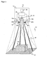
- FIG. 1 shows a schematic plan view of a sensor 10 for monitoring a space area 12.
- a housing 14 with a front screen 16 an image sensor 18 is arranged, which can generate image data of the spatial area 12 by means of an objective 20 and the front screen 16.
- This image sensor 18 is a line-shaped or matrix-shaped recording chip which receives a line-shaped or rectangular pixel image and can be for example a CCD or a CMOS sensor.
- a lighting 22 of the sensor 10 illuminates the part of the spatial region 12 to be monitored.
- the illumination 22 preferably produces a contrast pattern 24, which in FIG. 1 exemplified as a dot pattern on a stylized rectangular object 26.
- the contrast pattern 24 ensures a sufficient contrast of the recorded image data.
- individual elements of the contrast pattern in the representation of FIG. 1
- a single luminous point 28 can help with the image evaluation on the basis of their known relative position to each other.
- the contrast pattern can be distorted by objects 26, the relative position of the elements of the contrast pattern 24 does not change with respect to one another.
- an estimate of the distance and the contour of the object 26 can be made.
- Alternative contrasting patterns 26 are conceivable, for example a line pattern or a grid or other regular patterns, but also irregular patterns and even self-similar patterns that can not be merged into each other under simple geometrical operations such as displacements, rotations and reflections. Such self-similar patterns allow a clear Assignment of characteristics of the pattern area to the relative position within the pattern.
- a light source in the illumination 22 is usually a semiconductor element, such as a laser or a light emitting diode.
- the contrast pattern may be generated by a mask, but preferably by a diffractive optical element having microstructures that deflect light of the semiconductor element in a predetermined manner in order to obtain the desired contrast pattern 26.
- the sensor 10 has a test mark illumination 30 in addition to the contrast illumination 22.
- the test mark illumination 30 is preceded by a beam-shaping optical system 32, such as a converging lens, via which light of the test mark illumination 30 is sharply imaged on the inside of the front pane 16 and generates a test mark 34 there as a light reflection.
- the objective 20 is designed such that the beam path of the test mark 34 generates a sharp image of the test mark 34 on the image sensor 18 through the objective 20, preferably in the edge region of the objective 20.
- test mark 34 may be constructed of one or more semiconductor light elements so that the pattern of the test mark 34 corresponds to the multiple light source.
- the beam-forming optic 32 may be another diffractive optical element or mask that shapes the pattern of the test mark 34.
- the test mark illumination 30 can consist of passive elements, in particular reflectors, which are illuminated by an active illumination and thus generate the test mark 34. As a light source for this illumination can in turn serve a separate semiconductor element, or the light is coupled out of the contrast pattern illumination 22.
- the contrast pattern illumination 22 itself not only illuminates the spatial region 12, but also generates the test mark 34 by partial reflection on the inside of the front pane 16 or a reflective region on the front side of the sensor 10.
- This dual function of the contrast illumination 22 on the one hand has the advantage that no additional test mark illumination 30 is required, and on the other hand, the intensity of the test mark 34 is also the basis for a measure of the output power of the contrast illumination 22, so that this output power can be checked.
- a controller 36 of the sensor 10 is connected to the image sensor 18, the contrast illumination 22 and the test mark illumination 30. Furthermore, a warning or shutdown device 38 is connected to the controller 36. Control 36 as well as warning or shutdown device 38 may, as in FIG. 1 represented, parts of an external Control or an external computer system, but they can also be integrated into the sensor 10 within the housing 14.
- the controller 36 turns on and off the contrast pattern illumination 22 and the check mark illumination 30 as needed and regulates their performance. It also receives image data of the image sensor 18 both from the space area 12 and image data of the check mark 34.
- a warning is issued via the warning or shutdown device 38 or a source of danger is secured.
- 12 protective fields are often created in the room area, in which no interference may take place, for example, around dangerous machine parts.
- a warning area is often created around the actual protective field, where an inadmissible object engagement initially triggers only a warning and only with continued intervention in the protective field, the source of danger is hedged, so for example the machine the dangerous machine part is switched off or brought into a safe position. It is also conceivable to pre-register in the spatial area 12 existing objects 26 as well as certain permitted movement patterns of defined objects and to distinguish them during operation from impermissible object interventions, that is to say they do not react during their intervention.
- the senor 10 is designed fail-safe. This means inter alia that the sensor 10 can test itself in cycles below the required response time and that the output to and the warning or shutdown device 38 itself is safe, designed for example two-channel. Likewise, the controller 36 is self-confident, thus evaluating two-channel or uses algorithms that can test themselves.
- test mark 34 is explained in more detail.
- FIG. 2 those components of the sensor 10 are shown in schematic plan view, which relate to the generation and imaging of the test mark 34.
- the objective 20 is a lens system consisting of successively arranged partial lenses 20a-20d.
- the partial lenses 20a-20d are to be understood merely as a model for a deviation of the imaging properties of an ideal lens.
- the FIGS. 2a and 2b differ from each other only in that the partial lens 20b is tilted, the lens 20 of the FIG. 2b So has a aberration that leads to a distortion of the image 35 of the test mark 34 on the image sensor 18.
- Reasons for such aberrations can be, for example, soiling, damage, changes in position or temperature fluctuations.
- the controller 36 is able to detect such aberrations. This can be done, for example, by comparison with a previously learned or a predefined expectation or reference.
- the brightness profile and the geometric shape of the image 35 can be evaluated by means of image evaluation, so as to evaluate the correct distortion correction, the function of the image sensor 18 or the contamination of the front screen 16. A higher degree of contamination reduces the global brightness and can therefore be read in the brightness profile.
- the controller 36 can not only qualitatively recognize the presence of such a aberration, but also quantitatively determine the aberrations and in particular the distortion on the basis of the distortions of the image 35. This also makes it possible to correct the correspondingly recorded image data from the spatial area 12 and it is not necessary to immediately secure the source of danger on account of the imaging error. To increase the availability of the sensor 10, such a hedge takes place only when sufficient correction is no longer possible.
- the more complex the test mark 34 the more accurate the correction can be.
- a distortion, as shown by tilting the partial lens 20 in FIG. 2b is shown, but causes a global distortion error, so that a single light spot is sufficient.
- the test mark 34 can already be generated by a single LED as a test mark illumination 30.
- test mark 34 is reflected in an edge region of the front screen 16, so that the image 35 is generated in a region of the image sensor 18 that is not required for monitoring the spatial region 12, the test can be parallel to the actual Monitoring function to be performed. This can be guaranteed in each evaluation cycles below the response time, such as with each evaluation cycle of the image data from the space area 12, and thus virtually anytime, the functionality. Alternatively, it is conceivable to carry out the test only on request or at fixed times, for example when the sensor 10 is switched on.
- the contrast illumination 22 and the test mark illumination 30 operate at a different frequency. Any light in the ultraviolet, visible or infrared range is considered.
- the windshield 16 is dichroic in this case, so transmits the useful light of the contrast illumination 22 for the illumination of the space area 12, however, reflects the test light of the test light illumination 30 for the generation of the test mark 34. Thus, no disturbing test light enters the space area 12 and the Controller 36 can clearly distinguish test light and useful light for simplified image evaluation based on the frequency.
- a very similar embodiment is possible by different polarizations of the contrast illumination 22 and the test mark illumination 30 when the front screen 16 is polarization-selective or optically anisotropic, ie has different transmission and remission properties depending on the polarization state of the light, by corresponding polarizing filters in front of the illuminations 22, 30 are used.
- FIG. 3 shows in a schematic three-dimensional representation of the structure of a second embodiment of the sensor 10 according to the invention based on a three-dimensional stereoscopic camera. Same or analogous components to the first embodiment according to Figures 1 and 2 are provided with the same reference numerals and the variants described in connection with the first embodiment are also conceivable for the second embodiment.
- Two camera modules are mounted at a known fixed distance from each other.
- the associated image sensors 18a, 18b record image data from the spatial area 12.
- Each image sensor 18a, 18b is preceded by its own objective 20a, 20b.
- the field of view of these camera modules is in FIG. 3 represented by dashed lines, each forming a viewing pyramid and encloses according to the invention, for example, 45 °, but may also be 90 ° and more, which makes increased demands on the components.
- an illumination source Arranged in the middle between the two camera modules 18a, 18b, 20a, 20b is an illumination source which combines both the function of the contrast illumination 22 and that of the test mark illumination 30.
- a diffractive Optical element 32 About a diffractive Optical element 32, both the contrast pattern 26 in the space area 12 as well as a respective test mark 34a, 34b on the inside of the front screen 16 in the field of view of the respective camera module 18a, 20a and 18b, 20b generated.
- the controller 36 is connected to both image sensors 18a, 18b and calculates three-dimensional image data of the space region 12 by means of a stereoscopic disparity estimation.
- the distance of the same image elements is triangulated by the known base distance of the image sensors 18a and 18b and the different perspective of the two captured images .
- a light transit time method or the active triangulation by means of elements of the contrast pattern 24 is also included in the invention.
- Three-dimensional image data allow for an expanded definition of better-matched and more closely-monitored protective fields, especially from an elevated position that is as disruptive to the user as possible.
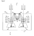
- FIG. 4 shows analogous to the FIG. 2 a plan view of only the part of the components of the sensor 10, which are associated with the generation of the test mark 34, in the stereoscopic second embodiment. It is opposite FIG. 3 an alternative shown in which the test mark illumination 30 not as a double function of the contrast illumination 22, but independently via their own beam shaper 32a, 32b for each camera module generates the test marks 34a, 34b.
- the individual elements differ from the FIG. 2a only in that most components are doubly provided, namely once for each camera module.
- the test mark illumination 30 is simply provided, but can also be designed in duplicate, if the additional equipment required for it is accepted.
- Each of the two images 35a, 35b of the test marks 34a, 34b is evaluated by the controller 36 to check the camera module in a very analogous manner to the first embodiment.
Landscapes
- Engineering & Computer Science (AREA)
- Multimedia (AREA)
- Signal Processing (AREA)
- Health & Medical Sciences (AREA)
- Biomedical Technology (AREA)
- General Health & Medical Sciences (AREA)
- Length Measuring Devices By Optical Means (AREA)
- Photometry And Measurement Of Optical Pulse Characteristics (AREA)
- Solid State Image Pick-Up Elements (AREA)
- Testing Of Individual Semiconductor Devices (AREA)
Claims (10)
- Capteur optoélectronique (10) à résolution locale, en particulier caméra de sécurité, qui comprend un boîtier (14), un capteur d'images (18) en forme de ligne ou de matrice pour engendrer des données-image d'une région spatiale (12) à surveiller, un objectif (20) de formage de faisceau, agencé dans le trajet optique depuis la région spatiale (12) vers le capteur d'images (18), ainsi qu'une unité de test (36), laquelle est réalisée pour contrôler la capacité de fonctionnement du capteur (10), dans lequel une marque de contrôle (34) est prévue dans le volume intérieur du boîtier sur un côté intérieur d'une plaque frontale (16) et est agencée de telle façon qu'il est possible de générer à travers l'objectif (20) sur le capteur d'images (18) une image (35) de la marque de contrôle (34) à travers l'objectif (20), et dans lequel l'unité de test (36) est réalisée pour contrôler la capacité de fonctionnement du capteur d'images (18) et l'intégrité du trajet optique dans le volume intérieur au moyen de données d'images de marque de contrôle dans l'image (35) de la marque de contrôle (34), et il est prévu un élément actif ou passif (30) pour la génération de marques de contrôle,
dans lequel il est prévu un moyen d'avertissement ou de sécurité (38) qui est réalisé pour reconnaître une intervention inadmissible d'un objet dans la région spatiale (12) et d'émettre un avertissement, ou de sécuriser une source de danger, dans lequel l'objectif (20) comprend un système à lentilles (20a-20d) avec au moins une lentille, ledit système à lentilles (20a-20d) étant réalisé et agencé de telle manière que des régions du système à lentilles (20a-20d) à travers lesquelles tombent la lumière de la marque de contrôle (34) engendrent une image nette de la marque de contrôle (34) sur le capteur d'images (18), et il est prévu un éclairage à motif de contraste (22) pour produire un motif de contraste (24) dans la région spatiale (12) qui est capable, à titre d'élément de génération actif de marque de contrôle ou par éclairage de l'élément de génération passif de marque de contrôle (30), d'engendrer simultanément la marque de contrôle (34),
caractérisé en ce que
la marque de contrôle (34) est un motif surfacique régulier, irrégulier ou dépourvu d'auto-similitude,
en ce que l'unité de test (36) est réalisée pour évaluer les données d'image de marque de contrôle en s'aidant d'un profil de luminosité et/ou de la forme géométrique par comparaison avec une référence apprise ou prédéterminée, et d'évaluer au moyen de la comparaison des propriétés du capteur d'images (18), de l'objectif (20) et/ou de la plaque frontale (16), en particulier de leur détérioration par encrassement, endommagement ou perte d'ajustement, et
en ce que l'unité de test (36) est en outre réalisée pour corriger des données d'images de la région spatiale en s'aidant des propriétés déterminées, en particulier avec un facteur de correction de distorsion - Capteur (10) selon la revendication 1,
dans lequel le capteur (10) est un capteur tridimensionnel selon le principe de la stéréoscopie, du temps de propagation de la lumière, ou de la triangulation active. - Capteur (10) selon la revendication 1 ou 2,
dans lequel sont prévus deux capteurs d'images (18a, 18b) avec respectivement un objectif (20a, 20b) et la marque de contrôle (30) est agencée de telle façon qu'une image respective (34a, 34b et, 35a, 35b) de la marque de contrôle (30) peut être engendrée aussi bien à travers l'un des objectifs (20a) sur l'un des capteurs d'images (18a) qu'à travers l'autre objectif (20b) sur l'autre capteur d'images (18b), et dans lequel l'unité de test (36) est réalisée pour reconnaître, en s'aidant de données d'images de marque de contrôle dans les images (35a, 35b), une modification de l'écartement de base des capteurs d'images (18a, 18b) l'un par rapport à l'autre. - Capteur (10) selon l'une des revendications précédentes,
dans lequel la marque de contrôle (34) est agencée sur le côté intérieur de la plaque frontale (16) à l'extérieur du trajet optique depuis la région spatiale (12) vers le capteur d'images (18), et dans lequel les éléments de génération de marque de contrôle (30) comprennent des sources de lumière ou des réflecteurs et sont réalisés pour engendrer la marque de contrôle (34) sous forme de réflexion de lumière sur la face intérieure de la plaque frontale (16). - Capteur (10) selon la revendication 4,
dans lequel la marque de contrôle (34) est un motif de lignes, un motif grillagé ou un motif de points, et dans lequel les éléments de génération de marque de contrôle (30) présentent une structure qui correspond au motif, ou dans lequel un formateur de rayons (32) est agencé dans le trajet optique depuis les éléments de génération de marque de contrôle (30) vers la face intérieure de la plaque frontale (16), en particulier une lentille ou un élément optique à diffraction. - Capteur (10) selon l'une des revendications précédentes,
dans lequel la plaque frontale (16) est dichroïque et réfléchi une lumière de contrôle d'une première fréquence qui engendre en fonctionnement la marque de contrôle (34), et qui transmet la lumière utile d'une seconde fréquence différente de la première fréquence qui éclaire en fonctionnement la région spatiale (12), et/ou dans lequel la plaque frontale (16) est sélective vis-à-vis de la polarisation et présente ainsi des propriétés différentes de transmission et de rémission port différente polarisation de la lumière et réfléchie le ainsi une lumière de contrôle d'une première polarisation qui engendre en fonctionnement la marque de contrôle (34), et transmet la lumière utile d'une seconde polarisation différente de la première polarisation qui éclaire en fonctionnement la région spatiale (12). - Procédé de test pour un capteur optoélectronique à résolution locale (10), en particulier pour une caméra de sécurité, dans lequel on engendre, à partir d'un capteur d'images en forme de ligne ou en forme de matrice (18), des données d'images d'une région spatiale à surveiller (12), et l'on contrôle la capacité de fonctionnement du capteur (10), dans lequel l'image d'une marque de contrôle (34) agencée sur une face intérieure d'une plaque frontale (16) dans l'espace intérieur d'un boîtier (14) du capteur (10), est formée (35) sur le capteur d'images (18) et on engendre à partir de celle-ci des données d'images de marque de contrôle, et dans lequel la capacité de fonctionnement du capteur d'images (18) et l'intégrité optique du trajet optique dans l'espace intérieur sont contrôlés en s'aidant des données d'images de marque de contrôle, dans lequel des interventions inadmissibles d'objets dans la région spatiale (12) sont reconnus à partir des données d'images de la région spatiale et en cas d'intervention inadmissible un avertissement est émis ou une source de danger est sécurisée, dans lequel une image nette de la marque de contrôle (34) est formée sur le capteur d'images (18) à travers un objectif (20) dans le trajet optique depuis la région spatiale (12) vers le capteur d'images (18), dans lequel des éléments de génération de marque de contrôle (30) illuminent la plaque frontale (16) ou bien des éléments de génération de marque de contrôle (30) passifs sont illuminés et réfléchissent la lumière vers la plaque frontale (16), et dans lequel un motif de contraste (24) est généré dans la région spatiale (12) au moyen d'un éclairage à motif de contraste (22), et dans lequel l'éclairage à motif de contraste (22) engendre simultanément la marque de contrôle (34) soit comme élément de génération de marque de contrôle (30) actif soit par éclairage de l'élément de génération de marque de contrôle (30) passif,
caractérisé en ce que
la marque de contrôle est un motif régulier, irrégulier ou dépourvu d'auto-similitude, et en ce que les données d'image de marque de contrôle sont évaluées en s'aidant d'un profil de luminosité et/ou de la forme géométrique par comparaison avec une référence apprise ou prédéterminée et, au moyen de la comparaison, on détermine des propriétés du capteur d'images (18), de l'objectif (20) et/ou de la plaque frontale (16), en particulier leur détérioration par encrassement, par endommagement ou par perte d'ajustement, et en ce que les données d'images de région spatiale sont corrigées en s'aidant des propriétés déterminées, en particulier avec un facteur de correction de distorsion. - Procédé de test selon la revendication 7,
dans lequel le capteur (10) est un capteur tridimensionnel selon le principe de la stéréoscopie, du temps de propagation de la lumière ou de la triangulation active. - Procédé de test selon la revendication 7 ou 8,
dans lequel, dans un capteur (10) avec deux capteurs d'images (18a, 18b) comprenant chacun un objectif (20a, 20b), la marque de contrôle (30) est agencée de telle façon qu'une image respective de la marque de contrôle (34a, 34b, 35a, 35b) est engendrée aussi bien à travers l'un des objectifs (20a) sur l'un des capteurs d'images (18a) qu'à travers l'autre objectif (20b) sur l'autre capteur d'images (18b), et à partir de données d'image de marque de contrôle dans les images (35a, 35b) on reconnaît une modification de la distance de base des capteurs d'images (18a, 18b) l'un par rapport à l'autre. - Procédé de test selon l'une des revendications 7 à 9,
dans lequel la marque de contrôle (34) apparaît par éclairage de la face intérieure de la plaque frontale (16) sous forme de réflexion de lumière à l'extérieur du trajet optique de la région spatiale (12) vers le capteur d'images (18), dans lequel la marque de contrôle (34) est un motif de ligne, un motif grillagé ou un motif de points.
Priority Applications (3)
| Application Number | Priority Date | Filing Date | Title |
|---|---|---|---|
| DE502007006045T DE502007006045D1 (de) | 2007-10-26 | 2007-10-26 | Ortsauflösender optoelektronischer Sensor mit Testeinheit und Testverfahren hierfür |
| EP07119372A EP2053868B1 (fr) | 2007-10-26 | 2007-10-26 | Capteur optoélectronique haute résolution doté d'une unité de test et procédé de test correspondant |
| AT07119372T ATE492992T1 (de) | 2007-10-26 | 2007-10-26 | Ortsauflösender optoelektronischer sensor mit testeinheit und testverfahren hierfür |
Applications Claiming Priority (1)
| Application Number | Priority Date | Filing Date | Title |
|---|---|---|---|
| EP07119372A EP2053868B1 (fr) | 2007-10-26 | 2007-10-26 | Capteur optoélectronique haute résolution doté d'une unité de test et procédé de test correspondant |
Publications (2)
| Publication Number | Publication Date |
|---|---|
| EP2053868A1 EP2053868A1 (fr) | 2009-04-29 |
| EP2053868B1 true EP2053868B1 (fr) | 2010-12-22 |
Family
ID=39204796
Family Applications (1)
| Application Number | Title | Priority Date | Filing Date |
|---|---|---|---|
| EP07119372A Not-in-force EP2053868B1 (fr) | 2007-10-26 | 2007-10-26 | Capteur optoélectronique haute résolution doté d'une unité de test et procédé de test correspondant |
Country Status (3)
| Country | Link |
|---|---|
| EP (1) | EP2053868B1 (fr) |
| AT (1) | ATE492992T1 (fr) |
| DE (1) | DE502007006045D1 (fr) |
Families Citing this family (7)
| Publication number | Priority date | Publication date | Assignee | Title |
|---|---|---|---|---|
| DE102009007840A1 (de) * | 2009-02-06 | 2010-08-12 | Adc Automotive Distance Control Systems Gmbh | Verfahren zur Kalibrierung eines kamerabasierten Systems |
| DE202011005083U1 (de) * | 2011-04-09 | 2011-06-09 | Maier, Florian, 82205 | Vorrichtung zum Kalibrieren von Mehrkamera-Aufnahmevorrichtungen |
| DE102012003011B4 (de) * | 2012-02-15 | 2013-09-05 | 3Ality Digital Systems, Llc | Nahtarget und Verwendung eines Nahtargets bei der Kalibrierung einer 3D-Kamera |
| US8872113B2 (en) * | 2012-02-21 | 2014-10-28 | Rockwell Automation Technologies, Inc. | System to test performance of pixels in a sensor array |
| DE102013208248B4 (de) | 2012-05-29 | 2023-11-16 | pmdtechnologies ag | Verfahren zur Charakterisierung eines optischen Systems mit Hilfe eines 3D-Sensors und Lichtlaufzeitkamera |
| EP3651458B1 (fr) * | 2018-11-08 | 2020-09-09 | Sick Ag | Caméra stéréo sécurisée et procédé de vérification de la capacité de fonctionnement des capteurs d'image |
| DE102019121557B4 (de) * | 2019-08-09 | 2021-07-22 | Basler Ag | Kamera sowie Verfahren |
Family Cites Families (6)
| Publication number | Priority date | Publication date | Assignee | Title |
|---|---|---|---|---|
| DE69526635T2 (de) * | 1994-12-29 | 2002-12-05 | Koninklijke Philips Electronics N.V., Eindhoven | Bilderzeugungsgerät und Verfahren zur Verbesserung geometrischer optischer Bildverzerrungen |
| JP3499405B2 (ja) * | 1997-06-30 | 2004-02-23 | アマノ株式会社 | 動体識別センサ用自己診断方法とその装置 |
| DE10245720A1 (de) * | 2002-09-24 | 2004-04-01 | Pilz Gmbh & Co. | Verfahren un Vorrichtung zum Absichern eines Gefahrenbereichs |
| DE102004035243B4 (de) * | 2004-07-21 | 2007-09-20 | Sick Ag | Kameraanordnung |
| DE102005056265A1 (de) * | 2005-11-14 | 2007-05-16 | Pilz Gmbh & Co Kg | Vorrichtung und Verfahren zum Überwachen eines Raumbereichs, insbesondere zum Absichern eines Gefahrenbereichs einer automatisiert arbeitenden Anlage |
| DE102006004193A1 (de) * | 2006-01-27 | 2007-08-16 | Sick Ag | Vorrichtung zur optoelektronischen Überwachung von Objekten |
-
2007
- 2007-10-26 DE DE502007006045T patent/DE502007006045D1/de active Active
- 2007-10-26 AT AT07119372T patent/ATE492992T1/de active
- 2007-10-26 EP EP07119372A patent/EP2053868B1/fr not_active Not-in-force
Also Published As
| Publication number | Publication date |
|---|---|
| DE502007006045D1 (de) | 2011-02-03 |
| EP2053868A1 (fr) | 2009-04-29 |
| ATE492992T1 (de) | 2011-01-15 |
Similar Documents
| Publication | Publication Date | Title |
|---|---|---|
| DE102007008806C5 (de) | Optoelektronische Überwachung mit Test durch Dynamisierung | |
| EP1933167B1 (fr) | Capteur optoélectronique et procédé correspondant de détection et de détermination de la distance d'un objet | |
| EP3260885B1 (fr) | Capteur optoélectronique et procédé de détection d'objets | |
| EP2202994B1 (fr) | Caméra 3D pour la surveillance de pièces | |
| EP3054264B1 (fr) | Dispositif et procédé de détermination d'écart de positions nominales de deux corps | |
| EP1947477B1 (fr) | Capteur de triangulation doté d'une détermination d'éloignement à partir de la position et de la forme de la tache lumineuse | |
| EP2118555B1 (fr) | Dispositif de sécurité pour une machine | |
| EP1355128A1 (fr) | Alignement automatique d'un senseur | |
| EP1269762B1 (fr) | Dispositif de securite servant a empecher l'acces a une zone dangereuse et procede pour verifier la securite de fonctionnement d'un tel dispositif | |
| DE102007025373B3 (de) | Visuelle Überwachung mit Entfernungsbestimmung und Plausibilitätsprüfung anhand von Bildgrößen | |
| EP2166304A1 (fr) | Unité d'éclairage et procédé de production d'un modèle auto-dissemblable | |
| DE10143504A1 (de) | Überwachungsverfahren und optoelektronischer Sensor | |
| EP2053868A1 (fr) | Capteur optoélectronique haute résolution doté d'une unité de test et procédé de test correspondant | |
| DE102009030644B4 (de) | Berührungslose Erfassungseinrichtung | |
| EP3203263A1 (fr) | Capteur optoélectronique et procédé destiné à la saisie d'objets | |
| EP1246148B1 (fr) | Dispositif de surveillance d'une zone de protection | |
| EP2133619A1 (fr) | Surveillance tridimensionnelle et protection d'un domaine spatial | |
| DE10033608A1 (de) | Verfahren und Vorrichtung zum Absichern eines Gefahrenbereichs, insbesondere des Gefahrenbereichs einer automatisiert arbeitenden Maschine | |
| EP2019281A1 (fr) | Capteur en 3D et procédé destiné au fonctionnement d'un capteur en 3D | |
| EP1813961B1 (fr) | Dispositif destiné à la surveillance optoélectronique d'objets | |
| EP3736605B1 (fr) | Balayeur laser de sécurité et procédé | |
| DE102016110514A1 (de) | Vorrichtung und Verfahren zum Überwachen eines Raumbereichs, insbesondere zum Absichern eines Gefahrenbereichs einer automatisiert arbeitenden Anlage | |
| DE19718390A1 (de) | Opto-elektronischer Sensor | |
| EP2631668B1 (fr) | Système optique et procédé de contrôle de la capacité de fonctionnement d'un système optique | |
| DE202009012589U1 (de) | Optoelektronischer Sensor |
Legal Events
| Date | Code | Title | Description |
|---|---|---|---|
| PUAI | Public reference made under article 153(3) epc to a published international application that has entered the european phase |
Free format text: ORIGINAL CODE: 0009012 |
|
| AK | Designated contracting states |
Kind code of ref document: A1 Designated state(s): AT BE BG CH CY CZ DE DK EE ES FI FR GB GR HU IE IS IT LI LT LU LV MC MT NL PL PT RO SE SI SK TR |
|
| AX | Request for extension of the european patent |
Extension state: AL BA HR MK RS |
|
| 17P | Request for examination filed |
Effective date: 20091024 |
|
| 17Q | First examination report despatched |
Effective date: 20091130 |
|
| AKX | Designation fees paid |
Designated state(s): AT BE BG CH CY CZ DE DK EE ES FI FR GB GR HU IE IS IT LI LT LU LV MC MT NL PL PT RO SE SI SK TR |
|
| GRAP | Despatch of communication of intention to grant a patent |
Free format text: ORIGINAL CODE: EPIDOSNIGR1 |
|
| GRAS | Grant fee paid |
Free format text: ORIGINAL CODE: EPIDOSNIGR3 |
|
| GRAA | (expected) grant |
Free format text: ORIGINAL CODE: 0009210 |
|
| AK | Designated contracting states |
Kind code of ref document: B1 Designated state(s): AT BE BG CH CY CZ DE DK EE ES FI FR GB GR HU IE IS IT LI LT LU LV MC MT NL PL PT RO SE SI SK TR |
|
| REG | Reference to a national code |
Ref country code: GB Ref legal event code: FG4D Free format text: NOT ENGLISH |
|
| REG | Reference to a national code |
Ref country code: CH Ref legal event code: EP |
|
| REG | Reference to a national code |
Ref country code: IE Ref legal event code: FG4D |
|
| REF | Corresponds to: |
Ref document number: 502007006045 Country of ref document: DE Date of ref document: 20110203 Kind code of ref document: P |
|
| REG | Reference to a national code |
Ref country code: DE Ref legal event code: R096 Ref document number: 502007006045 Country of ref document: DE Effective date: 20110203 |
|
| REG | Reference to a national code |
Ref country code: NL Ref legal event code: VDEP Effective date: 20101222 |
|
| PG25 | Lapsed in a contracting state [announced via postgrant information from national office to epo] |
Ref country code: LT Free format text: LAPSE BECAUSE OF FAILURE TO SUBMIT A TRANSLATION OF THE DESCRIPTION OR TO PAY THE FEE WITHIN THE PRESCRIBED TIME-LIMIT Effective date: 20101222 |
|
| LTIE | Lt: invalidation of european patent or patent extension |
Effective date: 20101222 |
|
| PG25 | Lapsed in a contracting state [announced via postgrant information from national office to epo] |
Ref country code: BG Free format text: LAPSE BECAUSE OF FAILURE TO SUBMIT A TRANSLATION OF THE DESCRIPTION OR TO PAY THE FEE WITHIN THE PRESCRIBED TIME-LIMIT Effective date: 20110322 Ref country code: CY Free format text: LAPSE BECAUSE OF FAILURE TO SUBMIT A TRANSLATION OF THE DESCRIPTION OR TO PAY THE FEE WITHIN THE PRESCRIBED TIME-LIMIT Effective date: 20101222 Ref country code: FI Free format text: LAPSE BECAUSE OF FAILURE TO SUBMIT A TRANSLATION OF THE DESCRIPTION OR TO PAY THE FEE WITHIN THE PRESCRIBED TIME-LIMIT Effective date: 20101222 Ref country code: SE Free format text: LAPSE BECAUSE OF FAILURE TO SUBMIT A TRANSLATION OF THE DESCRIPTION OR TO PAY THE FEE WITHIN THE PRESCRIBED TIME-LIMIT Effective date: 20101222 Ref country code: LV Free format text: LAPSE BECAUSE OF FAILURE TO SUBMIT A TRANSLATION OF THE DESCRIPTION OR TO PAY THE FEE WITHIN THE PRESCRIBED TIME-LIMIT Effective date: 20101222 Ref country code: SI Free format text: LAPSE BECAUSE OF FAILURE TO SUBMIT A TRANSLATION OF THE DESCRIPTION OR TO PAY THE FEE WITHIN THE PRESCRIBED TIME-LIMIT Effective date: 20101222 |
|
| REG | Reference to a national code |
Ref country code: IE Ref legal event code: FD4D |
|
| PG25 | Lapsed in a contracting state [announced via postgrant information from national office to epo] |
Ref country code: GR Free format text: LAPSE BECAUSE OF FAILURE TO SUBMIT A TRANSLATION OF THE DESCRIPTION OR TO PAY THE FEE WITHIN THE PRESCRIBED TIME-LIMIT Effective date: 20110323 Ref country code: EE Free format text: LAPSE BECAUSE OF FAILURE TO SUBMIT A TRANSLATION OF THE DESCRIPTION OR TO PAY THE FEE WITHIN THE PRESCRIBED TIME-LIMIT Effective date: 20101222 Ref country code: ES Free format text: LAPSE BECAUSE OF FAILURE TO SUBMIT A TRANSLATION OF THE DESCRIPTION OR TO PAY THE FEE WITHIN THE PRESCRIBED TIME-LIMIT Effective date: 20110402 Ref country code: CZ Free format text: LAPSE BECAUSE OF FAILURE TO SUBMIT A TRANSLATION OF THE DESCRIPTION OR TO PAY THE FEE WITHIN THE PRESCRIBED TIME-LIMIT Effective date: 20101222 Ref country code: IS Free format text: LAPSE BECAUSE OF FAILURE TO SUBMIT A TRANSLATION OF THE DESCRIPTION OR TO PAY THE FEE WITHIN THE PRESCRIBED TIME-LIMIT Effective date: 20110422 Ref country code: PT Free format text: LAPSE BECAUSE OF FAILURE TO SUBMIT A TRANSLATION OF THE DESCRIPTION OR TO PAY THE FEE WITHIN THE PRESCRIBED TIME-LIMIT Effective date: 20110422 |
|
| PG25 | Lapsed in a contracting state [announced via postgrant information from national office to epo] |
Ref country code: SK Free format text: LAPSE BECAUSE OF FAILURE TO SUBMIT A TRANSLATION OF THE DESCRIPTION OR TO PAY THE FEE WITHIN THE PRESCRIBED TIME-LIMIT Effective date: 20101222 Ref country code: RO Free format text: LAPSE BECAUSE OF FAILURE TO SUBMIT A TRANSLATION OF THE DESCRIPTION OR TO PAY THE FEE WITHIN THE PRESCRIBED TIME-LIMIT Effective date: 20101222 Ref country code: NL Free format text: LAPSE BECAUSE OF FAILURE TO SUBMIT A TRANSLATION OF THE DESCRIPTION OR TO PAY THE FEE WITHIN THE PRESCRIBED TIME-LIMIT Effective date: 20101222 Ref country code: PL Free format text: LAPSE BECAUSE OF FAILURE TO SUBMIT A TRANSLATION OF THE DESCRIPTION OR TO PAY THE FEE WITHIN THE PRESCRIBED TIME-LIMIT Effective date: 20101222 |
|
| PLBI | Opposition filed |
Free format text: ORIGINAL CODE: 0009260 |
|
| 26 | Opposition filed |
Opponent name: LEUZE ELECTRONIC GMBH + CO. KG Effective date: 20110829 |
|
| PG25 | Lapsed in a contracting state [announced via postgrant information from national office to epo] |
Ref country code: IE Free format text: LAPSE BECAUSE OF FAILURE TO SUBMIT A TRANSLATION OF THE DESCRIPTION OR TO PAY THE FEE WITHIN THE PRESCRIBED TIME-LIMIT Effective date: 20101222 Ref country code: DK Free format text: LAPSE BECAUSE OF FAILURE TO SUBMIT A TRANSLATION OF THE DESCRIPTION OR TO PAY THE FEE WITHIN THE PRESCRIBED TIME-LIMIT Effective date: 20101222 |
|
| PLAX | Notice of opposition and request to file observation + time limit sent |
Free format text: ORIGINAL CODE: EPIDOSNOBS2 |
|
| REG | Reference to a national code |
Ref country code: DE Ref legal event code: R026 Ref document number: 502007006045 Country of ref document: DE Effective date: 20110829 |
|
| PG25 | Lapsed in a contracting state [announced via postgrant information from national office to epo] |
Ref country code: IT Free format text: LAPSE BECAUSE OF FAILURE TO SUBMIT A TRANSLATION OF THE DESCRIPTION OR TO PAY THE FEE WITHIN THE PRESCRIBED TIME-LIMIT Effective date: 20101222 |
|
| PLAF | Information modified related to communication of a notice of opposition and request to file observations + time limit |
Free format text: ORIGINAL CODE: EPIDOSCOBS2 |
|
| BERE | Be: lapsed |
Owner name: SICK A.G. Effective date: 20111031 |
|
| PLBB | Reply of patent proprietor to notice(s) of opposition received |
Free format text: ORIGINAL CODE: EPIDOSNOBS3 |
|
| PG25 | Lapsed in a contracting state [announced via postgrant information from national office to epo] |
Ref country code: MC Free format text: LAPSE BECAUSE OF NON-PAYMENT OF DUE FEES Effective date: 20111031 |
|
| REG | Reference to a national code |
Ref country code: CH Ref legal event code: PL |
|
| GBPC | Gb: european patent ceased through non-payment of renewal fee |
Effective date: 20111026 |
|
| REG | Reference to a national code |
Ref country code: FR Ref legal event code: ST Effective date: 20120629 |
|
| PG25 | Lapsed in a contracting state [announced via postgrant information from national office to epo] |
Ref country code: BE Free format text: LAPSE BECAUSE OF NON-PAYMENT OF DUE FEES Effective date: 20111031 Ref country code: LI Free format text: LAPSE BECAUSE OF NON-PAYMENT OF DUE FEES Effective date: 20111031 Ref country code: CH Free format text: LAPSE BECAUSE OF NON-PAYMENT OF DUE FEES Effective date: 20111031 |
|
| PG25 | Lapsed in a contracting state [announced via postgrant information from national office to epo] |
Ref country code: GB Free format text: LAPSE BECAUSE OF NON-PAYMENT OF DUE FEES Effective date: 20111026 Ref country code: FR Free format text: LAPSE BECAUSE OF NON-PAYMENT OF DUE FEES Effective date: 20111102 |
|
| PG25 | Lapsed in a contracting state [announced via postgrant information from national office to epo] |
Ref country code: MT Free format text: LAPSE BECAUSE OF FAILURE TO SUBMIT A TRANSLATION OF THE DESCRIPTION OR TO PAY THE FEE WITHIN THE PRESCRIBED TIME-LIMIT Effective date: 20101222 |
|
| PG25 | Lapsed in a contracting state [announced via postgrant information from national office to epo] |
Ref country code: LU Free format text: LAPSE BECAUSE OF NON-PAYMENT OF DUE FEES Effective date: 20111026 |
|
| PLBP | Opposition withdrawn |
Free format text: ORIGINAL CODE: 0009264 |
|
| PLBD | Termination of opposition procedure: decision despatched |
Free format text: ORIGINAL CODE: EPIDOSNOPC1 |
|
| PG25 | Lapsed in a contracting state [announced via postgrant information from national office to epo] |
Ref country code: TR Free format text: LAPSE BECAUSE OF FAILURE TO SUBMIT A TRANSLATION OF THE DESCRIPTION OR TO PAY THE FEE WITHIN THE PRESCRIBED TIME-LIMIT Effective date: 20101222 |
|
| PG25 | Lapsed in a contracting state [announced via postgrant information from national office to epo] |
Ref country code: HU Free format text: LAPSE BECAUSE OF FAILURE TO SUBMIT A TRANSLATION OF THE DESCRIPTION OR TO PAY THE FEE WITHIN THE PRESCRIBED TIME-LIMIT Effective date: 20101222 |
|
| PLBM | Termination of opposition procedure: date of legal effect published |
Free format text: ORIGINAL CODE: 0009276 |
|
| STAA | Information on the status of an ep patent application or granted ep patent |
Free format text: STATUS: OPPOSITION PROCEDURE CLOSED |
|
| REG | Reference to a national code |
Ref country code: AT Ref legal event code: MM01 Ref document number: 492992 Country of ref document: AT Kind code of ref document: T Effective date: 20121031 |
|
| 27C | Opposition proceedings terminated |
Effective date: 20130824 |
|
| PG25 | Lapsed in a contracting state [announced via postgrant information from national office to epo] |
Ref country code: AT Free format text: LAPSE BECAUSE OF NON-PAYMENT OF DUE FEES Effective date: 20121031 |
|
| PGFP | Annual fee paid to national office [announced via postgrant information from national office to epo] |
Ref country code: DE Payment date: 20181024 Year of fee payment: 12 |
|
| REG | Reference to a national code |
Ref country code: DE Ref legal event code: R119 Ref document number: 502007006045 Country of ref document: DE |
|
| PG25 | Lapsed in a contracting state [announced via postgrant information from national office to epo] |
Ref country code: DE Free format text: LAPSE BECAUSE OF NON-PAYMENT OF DUE FEES Effective date: 20200501 |