EP3203263A1 - Capteur optoélectronique et procédé destiné à la saisie d'objets - Google Patents
Capteur optoélectronique et procédé destiné à la saisie d'objets Download PDFInfo
- Publication number
- EP3203263A1 EP3203263A1 EP16154025.7A EP16154025A EP3203263A1 EP 3203263 A1 EP3203263 A1 EP 3203263A1 EP 16154025 A EP16154025 A EP 16154025A EP 3203263 A1 EP3203263 A1 EP 3203263A1
- Authority
- EP
- European Patent Office
- Prior art keywords
- projector
- sensor
- detection field
- scanning beam
- monitoring area
- Prior art date
- Legal status (The legal status is an assumption and is not a legal conclusion. Google has not performed a legal analysis and makes no representation as to the accuracy of the status listed.)
- Granted
Links
Images
Classifications
-
- G—PHYSICS
- G01—MEASURING; TESTING
- G01S—RADIO DIRECTION-FINDING; RADIO NAVIGATION; DETERMINING DISTANCE OR VELOCITY BY USE OF RADIO WAVES; LOCATING OR PRESENCE-DETECTING BY USE OF THE REFLECTION OR RERADIATION OF RADIO WAVES; ANALOGOUS ARRANGEMENTS USING OTHER WAVES
- G01S17/00—Systems using the reflection or reradiation of electromagnetic waves other than radio waves, e.g. lidar systems
- G01S17/02—Systems using the reflection of electromagnetic waves other than radio waves
- G01S17/04—Systems determining the presence of a target
-
- G—PHYSICS
- G01—MEASURING; TESTING
- G01S—RADIO DIRECTION-FINDING; RADIO NAVIGATION; DETERMINING DISTANCE OR VELOCITY BY USE OF RADIO WAVES; LOCATING OR PRESENCE-DETECTING BY USE OF THE REFLECTION OR RERADIATION OF RADIO WAVES; ANALOGOUS ARRANGEMENTS USING OTHER WAVES
- G01S17/00—Systems using the reflection or reradiation of electromagnetic waves other than radio waves, e.g. lidar systems
- G01S17/02—Systems using the reflection of electromagnetic waves other than radio waves
- G01S17/06—Systems determining position data of a target
- G01S17/08—Systems determining position data of a target for measuring distance only
-
- G—PHYSICS
- G01—MEASURING; TESTING
- G01S—RADIO DIRECTION-FINDING; RADIO NAVIGATION; DETERMINING DISTANCE OR VELOCITY BY USE OF RADIO WAVES; LOCATING OR PRESENCE-DETECTING BY USE OF THE REFLECTION OR RERADIATION OF RADIO WAVES; ANALOGOUS ARRANGEMENTS USING OTHER WAVES
- G01S17/00—Systems using the reflection or reradiation of electromagnetic waves other than radio waves, e.g. lidar systems
- G01S17/02—Systems using the reflection of electromagnetic waves other than radio waves
- G01S17/06—Systems determining position data of a target
- G01S17/42—Simultaneous measurement of distance and other co-ordinates
-
- G—PHYSICS
- G01—MEASURING; TESTING
- G01S—RADIO DIRECTION-FINDING; RADIO NAVIGATION; DETERMINING DISTANCE OR VELOCITY BY USE OF RADIO WAVES; LOCATING OR PRESENCE-DETECTING BY USE OF THE REFLECTION OR RERADIATION OF RADIO WAVES; ANALOGOUS ARRANGEMENTS USING OTHER WAVES
- G01S7/00—Details of systems according to groups G01S13/00, G01S15/00, G01S17/00
- G01S7/48—Details of systems according to groups G01S13/00, G01S15/00, G01S17/00 of systems according to group G01S17/00
- G01S7/481—Constructional features, e.g. arrangements of optical elements
- G01S7/4817—Constructional features, e.g. arrangements of optical elements relating to scanning
-
- G—PHYSICS
- G01—MEASURING; TESTING
- G01S—RADIO DIRECTION-FINDING; RADIO NAVIGATION; DETERMINING DISTANCE OR VELOCITY BY USE OF RADIO WAVES; LOCATING OR PRESENCE-DETECTING BY USE OF THE REFLECTION OR RERADIATION OF RADIO WAVES; ANALOGOUS ARRANGEMENTS USING OTHER WAVES
- G01S7/00—Details of systems according to groups G01S13/00, G01S15/00, G01S17/00
- G01S7/48—Details of systems according to groups G01S13/00, G01S15/00, G01S17/00 of systems according to group G01S17/00
- G01S7/497—Means for monitoring or calibrating
- G01S7/4972—Alignment of sensor
-
- G—PHYSICS
- G01—MEASURING; TESTING
- G01S—RADIO DIRECTION-FINDING; RADIO NAVIGATION; DETERMINING DISTANCE OR VELOCITY BY USE OF RADIO WAVES; LOCATING OR PRESENCE-DETECTING BY USE OF THE REFLECTION OR RERADIATION OF RADIO WAVES; ANALOGOUS ARRANGEMENTS USING OTHER WAVES
- G01S7/00—Details of systems according to groups G01S13/00, G01S15/00, G01S17/00
- G01S7/48—Details of systems according to groups G01S13/00, G01S15/00, G01S17/00 of systems according to group G01S17/00
- G01S7/51—Display arrangements
Definitions
- the invention relates to an optoelectronic sensor, in particular a laser scanner, and to a method for detecting objects according to the preamble of claims 1 and 13, respectively.
- a laser beam generated by a laser periodically sweeps over a monitoring area by means of a deflection unit.
- the light is remitted to objects in the surveillance area and evaluated in the scanner. From the angular position of the deflection is on the angular position of the object and from the light transit time using the speed of light in addition to the removal of the object from the laser scanner closed.
- the location of an object in the surveillance area is recorded in two-dimensional polar coordinates. This allows the positions of objects to be determined or their contour to be determined.
- Laser scanners are used in safety technology to monitor a source of danger such as a dangerous machine.
- a safety laser scanner is from the DE 43 40 756 A1 known.
- a protective field is monitored, which must not be entered by the operating personnel during operation of the machine. If the laser scanner detects an inadmissible protective field intervention, for example a leg of an operator, it triggers an emergency stop of the machine. Other interference with the protective field, for example due to static machine parts, can be taught in advance as permissible.
- Safety laser scanners must work particularly reliably and therefore meet high safety requirements, for example the standard EN 13849 for machine safety and the device standard EN61496 for non-contact protective devices (BWS). To meet these safety standards, a number of measures must be taken, such as safe electronic evaluation by means of redundant, diverse electronics, function monitoring or especially monitoring of the contamination of optical components, in particular a windscreen.
- Detection fields are virtually defined subareas of the monitoring area of the laser scanner, which are usually configured at set-up time and evaluated at runtime.
- the detection fields determine which areas of the captured scene are to be evaluated for objects, which may only refer to one specific time and the definition of the detection fields changes at a different time.
- the type of detection field determines which type of evaluation is to be performed and which reaction triggers an object intervention in a detection field. For the protective fields already mentioned, object interventions lead to a safety-related shutdown.
- Warning fields are usually located in front of protective fields and trigger an alarm without intervening directly in the system, and should generally prevent further intervention in a protective field in time by the alarm.
- Automation fields are the general complementary term for protection and warning fields, ie not safety-relevant, but are used, for example, in the form of a function field as a virtual switch, as a measuring field for determining volumes or for other measurements.
- detection fields especially in the case of safety-relevant protective fields, is essential for the proper functioning of the laser scanner. Nevertheless, the user is currently provided relatively little resources. Usually, an input of the limits of the detection field in the laser scanner or in a configuration software. The dimensions of the detection field must be known, and there is no feedback in the actual scene except through tedious testing with a test rod. Although it is also known to mark the protective fields by adhesive tapes or colored surfaces. However, this does not relieve the user from having to make sure that the areas marked in this way are configured as detection fields in the laser scanner.
- a laser scanner which emits a visible light beam in the direction of an object detected in a protected area. This makes it easier to check the configured protective fields, but it is still only possible to perform a punctual test and is missing an overall overview.
- the US 8 638 446 discloses a laser scanner with an integrated projector capable of projecting visible information onto an environmental object.
- This information is, for example, images, CAD data or point clouds from scanner measurements.
- a texture over an object or a virtual object in a planned or ideal configuration is projected over the actual object.
- neither protection by means of protective fields nor visualization of detection fields is provided.
- the US 2005/0052720 A1 deals with a laser projection system in which a laser beam is steerable in two dimensions with the aid of two mutually perpendicular, rotating deflection mirrors. But there is no connection with laser scanners.
- an optoelectronic sensor in particular a laser scanner, and a method for detecting objects according to claim 1 or 13.
- the sensor periodically passes a scanning beam of a light transmitter through the surveillance area by means of a movable deflection unit and evaluates the reception signal of a light receiver.
- the movable deflection is often a rotating mirror, but it can also rotate, for example, a measuring head with light emitter and light receiver.
- the sensor monitors a detection field or a plurality of detection fields for object interventions.
- the invention is based on the basic concept of visualizing the detection fields in the monitoring area.
- a projector which knows the detection fields, for example by common access of the projector and evaluation unit to a corresponding configuration memory or a data or control connection between the projector and the evaluation unit.
- the visualization may mean that the entire detection field is homogeneous or illuminated with a pattern.
- the invention has the advantage that the establishment and control of detection fields is considerably facilitated. It also eliminates a significant source of error, because it is immediately apparent where the detection fields are, and therefore there can be no unnoticed discrepancies between the desired and the actual detection fields.
- the visualization is primarily intended for initial configuration, it may also be useful during operation to display the detection fields permanently or on demand, such as to help individuals in the laser scanner's operating area to avoid accidental interference with the detection field, or to adapt to a new configuration can get used to.
- the projector preferably has a rotating light source.
- the projection method then resembles the scanning method of the laser scanner.
- a rotating light source is understood to mean both a physically moved light source and a rotational movement of only the light beam with the aid of a rotating mirror.
- the light source is preferably a laser in the visible wavelength range.
- the projector preferably has a tilting unit for adjusting the inclination of the light source. This makes the projection in elevation changeable.
- a tilting unit for adjusting the inclination of the light source.
- This makes the projection in elevation changeable.
- the inclination can be achieved by tilting the light source itself, but also by tilting a downstream mirror, in particular a rotating mirror.
- a controllable micromirror DLP, Digital Light Processing
- a control unit of the projector is preferably designed to visualize the detection field by projection onto the ground.
- the floor offers a clearly visible projection surface.
- detection fields can be adapted particularly easily to sources of danger or work areas.
- the control unit is preferably designed for a calibration in which the height and / or inclination of the projector is determined. From these parameters, the control unit calculate how the detection fields are suitably projected onto the ground from their own perspective. Without calibration, the values would have to be predefined, for example parameterized, or there would be an inaccuracy if the detection fields were not configured at ground level, which is practically always the case.
- the projector preferably has a tilt sensor. This allows the calibration to the actual slope at any time automatically without intervention of the operator.
- the projector preferably has a detector to determine the height of the projector. So the height is automatically detected. For example, a small detector is mounted below the light source of the projector and the height is then triangulated using the projection beam. With tilt sensor and detector or other means of detection for inclination and height then an overall automatic calibration is possible and no manual calibration required.
- the projector is preferably designed as an additional module.
- the projector is a separate attachment.
- calibration surfaces are advantageous, bring the projector and laser scanner in a well-defined and known relative position.
- An advantage of an accessory is the possibility of retrofitting.
- only a service technician or a person responsible for the system with a single additional module can configure any number of laser scanners successively.
- the projector is preferably integrated in the sensor.
- the projector uses the deflection unit of the scanning beam. It also rotates, for example, the light source of the projector in a movable measuring head with light emitter and light receiver of the scanning beam.
- the visible light beam of the projector is coupled to the rotating mirror in an angle corresponding to the respective desired inclination.
- the projector preferably has a plurality of rotating light sources with different wavelengths.
- the light sources again preferably have a mutual angular offset. Different wavelengths result in new display options, with which detection fields or parts thereof can be visualized in their own colors.
- a preferred embodiment shows different types of detection fields in their own color, such as warning fields in a different color than protective fields.
- the sensor is preferably designed as a rangefinder in that the evaluation unit determines the light transit time between emission and reception of the light signal and therefrom the distance of an object and / or wherein an angle measuring unit is provided for detecting the angular position of the deflection unit.
- the distance and angle measurements provide complete two-dimensional polar coordinates with which any detection fields can be defined in a monitoring area designed as a level. This corresponds to a projector, which can also visualize any geometric shapes in polar coordinates and thus all detection fields by rotation and tilting of the light source.
- the sensor is preferably designed as a safety laser scanner and has a safety output (OSSD, Output Signal Switching Device), wherein the evaluation unit is designed to determine whether an object in a trained as a protective field detection field is within the monitoring area, then a safety-related shutdown signal via the safety output.
- a safety output (OSSD, Output Signal Switching Device)
- the evaluation unit is designed to determine whether an object in a trained as a protective field detection field is within the monitoring area, then a safety-related shutdown signal via the safety output.
- the conformity of desired and actual protective fields is particularly critical and therefore their intuitive recognition is particularly helpful.
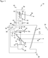
- Fig. 1 shows a schematic sectional view through a laser scanner 10.
- a light emitter 12 for example with a laser light source, generated by means of a transmitting optical system 14, a transmitted light beam 16, which is deflected via a mirror 18a at a movable deflection unit 18 in a monitoring area 20. If the transmitted light beam 16 in the monitoring area 20 is incident on an object, then remitted light 22 returns to the laser scanner 10 and is detected there via the deflection unit 18 and by means of a receiving optical unit 24 by a light receiver 26, for example a photodiode or an APD (Avalanche Photo Diode).
- APD Anavalanche Photo Diode
- the deflection unit 18 is configured in this embodiment as a rotating mirror, which rotates continuously by driving a motor 28.
- the respective angular position of the motor 28 or the deflection unit 18 is detected by an encoder, which comprises, for example, a code disk 30 and a fork light barrier 32.
- the transmitted light beam 16 generated by the light emitter 12 thus passes over the monitoring area 20 generated by the rotational movement.
- a rotating mirror it is also possible to form the deflection unit 18 as a rotating optical head in which the light emitter 12 and / or light receiver 26 and possibly further elements are housed.
- the coupling via the mirror 18a and the design of the transmitting optics 14 and the receiving optics 24 can also be varied, for example via a beam-shaping mirror as a deflection unit, a different arrangement of the lenses or additional lenses.
- laser scanners are also known in a double-eye arrangement with adjacent transmitting and receiving paths.
- the angular position of the deflection unit 18 measured by the encoder 30, 32 can be used to determine the angular position of the object in the monitoring area 20.
- the light transit time from emitting a light signal to receiving it after reflection on the object in the surveillance area 20 is detected and closed using the speed of light on the distance of the object from the laser scanner 10.
- This evaluation takes place in an evaluation unit 34, which is connected to the light emitter 12, the light receiver 26, the motor 28 and the encoder 32.
- the evaluation unit 34 checks whether an impermissible object intervenes in a protection area defined within the monitoring area 20. If this is the case, a safety signal 36 (OSSD, output signal switching device) outputs a safety signal to a monitored hazard source, for example a machine.
- the laser scanner 10 is in such safety applications by measures according to the standards mentioned in the introduction a safe laser scanner.
- an interface for outputting measurement data or, for example, for parameterizing the laser scanner 10 is provided instead of the safety output 36 or in addition thereto.
- a housing 38 which has a front screen 40 in the region of the light exit and light entry.
- the design of the housing 38 with a rear area without windscreen 40 is purely exemplary. In other embodiments, the windshield 40 includes the entire 360 ° viewing area.
- the evaluation unit 34 For protective field monitoring, the evaluation unit 34 must be aware of the protective field limits. Although the example of protective fields is explained below, this also applies correspondingly to other detection fields, that is to say in particular warning fields or also automation fields.
- the configuration of protective field boundaries takes place, for example, by parameterization or via software of an installation computer connected to the laser scanner 10.
- the laser scanner 10 has a projector 42, with the help of which protection fields can be projected into the monitoring area 20.
- the projector preferably has its own control unit 44, which is connected via connections 46, 48 to the evaluation unit 34.
- control unit 44 it is also conceivable to integrate the functionality of the control unit 44 into the evaluation unit 34.
- the projector 42 in the embodiment uses FIG. 1 a projecting light emitter 54 rotating by means of motor 50 and adjustable in inclination by means of tilting device 52, for example a laser light source in the visible wavelength range with unillustrated projection optics. Thereby, a visible projection light beam 56 is emitted into the surveillance area 20.
- the projection light beam 56 rotates fast enough that a continuous circle is visible in the monitoring area 20 and especially there on the ground. At the same time, the tilt is fast enough to vary the radius of the circles during the rotations and thus to draw the total number of protection fields in polar coordinates.
- the projector 42 can also be integrated into the housing 40 of the actual laser scanner, in particular with shared use of the motor 28 or even the deflection unit 18.
- the projection light transmitter 54 does not need to rotate itself to generate a rotational movement, but can also use a rotating deflection unit, both in the case of a separate plug-in device as well as in an integration in the housing 40th
- the tilt unit 52 also preferably does not generate direct movement of the projection light transmitter 54, although that is possible, but rather moves a mirror. This may be an additional mirror in the path of the projection light beam 56 or a mirror of the deflection unit. Particularly suitable are controllable micromirrors (DLP, Digital Light Processing).
- control unit 44 and the evaluation unit 34 have a direct connection via the terminals 46, 48, it is also conceivable first to read the configuration data with the protective field boundaries, for example with a USB stick to a corresponding interface on the housing 38, and then into the projector 42ndivaster.
- the configuration data can also be transmitted via a connected computer or a higher-level controller.
- control unit 44 If protective fields are to be drawn on the ground, the control unit 44 must be aware of the position of the laser scanner 10, namely its height above the ground and its inclination. Otherwise, the projection would lead to considerable distortions because a protective field is configured in practice significantly above the level of the ground.
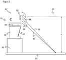
- FIG. 2 shows a schematic representation of the laser scanner 10 in an application environment. For the sake of clarity, only a small part of the elements of the laser scanner is shown, but then provided with the same reference numerals as in FIG. 1 ,
- the laser scanner 10 stands on a pedestal 60 at a certain height above the floor 62.
- the projector 42 produces the visible projection beam 56, the one point on impact with the floor 62 and in the course of superimposed rotational and tilting movement by motor 50 and tilting device 52nd the protective fields draws.
- the standards in FIG. 2 are for explanation purposes only and are rather untypical, since the laser scanner 10 is clearly mounted higher in most cases and small compared to the distance and dimensions of surveillance area 20 and protective fields.
- inclination angle ⁇ and height h above the ground 62 should be known.
- inclination sensors (not shown) may preferably be used in two axes, from which the inclination in all directions can then be derived. This inclination is then compensated for in the projection in the tilt angles of the tilting device 52.
- the height may be determined by the projector 42 in a preferred embodiment.
- the projection light transmitter 54 is tilted by means of the tilting device 52 in a calibration step in a fixed angular position, ie with the motor 50, until the projection light beam 64 reflected at the bottom 62 strikes a height measuring light receiver 66 mounted slightly below the projection light transmitter 54. Knowing the previously determined inclination of the laser scanner 10 and the internal geometry, in particular the distance between the projection light transmitter 54 and the height measuring light receiver 66, the height h can be calculated from the tilt angle required for this constellation.
- only one projection light transmitter 54 is provided in each case. It is conceivable to use several light sources of different colors, preferably with mutual angular offset. As a result, certain protective fields or parts thereof can be identified by different colors. It is also possible to display the type of a detection field, for example, to display warning fields in blue and protective fields in red or yellow.
- the projection of detection fields is particularly useful when a plurality of laser scanners 10 according to the invention are mounted together on a surveillance area. Then it is immediately apparent where all the detection fields are. By different colors that can be assigned to the involved laser scanners 10 and so the common configuration can be significantly accelerated.
- the invention is also suitable for mobile applications, for example in securing vehicles or AGVs (autonomous guided vehicle). There, it is particularly advantageous in configuration and operation when the particular speed-adapted detection fields are displayed, for example, to indicate to persons the critical area from which they must stay away.
Landscapes
- Engineering & Computer Science (AREA)
- Physics & Mathematics (AREA)
- Computer Networks & Wireless Communication (AREA)
- General Physics & Mathematics (AREA)
- Radar, Positioning & Navigation (AREA)
- Remote Sensing (AREA)
- Electromagnetism (AREA)
- Optical Radar Systems And Details Thereof (AREA)
- Length Measuring Devices By Optical Means (AREA)
Priority Applications (2)
| Application Number | Priority Date | Filing Date | Title |
|---|---|---|---|
| EP16154025.7A EP3203263B1 (fr) | 2016-02-03 | 2016-02-03 | Capteur optoélectronique et procédé destiné à la saisie d'objets |
| US15/423,075 US10436901B2 (en) | 2016-02-03 | 2017-02-02 | Optoelectronic sensor and method for detecting objects |
Applications Claiming Priority (1)
| Application Number | Priority Date | Filing Date | Title |
|---|---|---|---|
| EP16154025.7A EP3203263B1 (fr) | 2016-02-03 | 2016-02-03 | Capteur optoélectronique et procédé destiné à la saisie d'objets |
Publications (2)
| Publication Number | Publication Date |
|---|---|
| EP3203263A1 true EP3203263A1 (fr) | 2017-08-09 |
| EP3203263B1 EP3203263B1 (fr) | 2018-04-18 |
Family
ID=55299355
Family Applications (1)
| Application Number | Title | Priority Date | Filing Date |
|---|---|---|---|
| EP16154025.7A Active EP3203263B1 (fr) | 2016-02-03 | 2016-02-03 | Capteur optoélectronique et procédé destiné à la saisie d'objets |
Country Status (2)
| Country | Link |
|---|---|
| US (1) | US10436901B2 (fr) |
| EP (1) | EP3203263B1 (fr) |
Cited By (2)
| Publication number | Priority date | Publication date | Assignee | Title |
|---|---|---|---|---|
| CN109425307A (zh) * | 2017-08-30 | 2019-03-05 | 赫克斯冈技术中心 | 用于扫描物体和投影信息的测量仪器 |
| DE102018216705A1 (de) * | 2018-09-28 | 2020-04-02 | Ibeo Automotive Systems GmbH | LIDAR-Messsystem sowie Verfahren für ein LIDAR-Messsystem |
Families Citing this family (10)
| Publication number | Priority date | Publication date | Assignee | Title |
|---|---|---|---|---|
| EP3193195B1 (fr) * | 2016-01-18 | 2018-07-25 | SICK Engineering GmbH | Capteur optique |
| WO2019035363A1 (fr) * | 2017-08-18 | 2019-02-21 | 株式会社小糸製作所 | Capteur de reconnaissance, son procédé de commande, automobile, appareil d'éclairage de véhicule, système d'identification d'objet et procédé d'identification d'objet |
| EP3617752B1 (fr) * | 2018-08-27 | 2021-07-21 | Syncmold Enterprise Corp. | Système et procédé de détection |
| DE102019102466A1 (de) * | 2019-01-31 | 2020-08-06 | Endress+Hauser Conducta Gmbh+Co. Kg | Optischer Sensor |
| JP2020165930A (ja) * | 2019-03-29 | 2020-10-08 | Idec株式会社 | 表示機能付き検出装置および表示・検出システム |
| DE102019112300A1 (de) * | 2019-05-10 | 2020-11-12 | Sick Ag | Bestimmung der Entfernung eines Objekts |
| US11972612B2 (en) * | 2021-02-18 | 2024-04-30 | Fca Us Llc | Techniques to automatically verify object detection, classification, and depth for automated driving systems |
| JP7788301B2 (ja) * | 2022-02-10 | 2025-12-18 | 株式会社小糸製作所 | LiDAR装置 |
| EP4401045B1 (fr) | 2023-01-10 | 2024-10-30 | Sick Ag | Configuration de capteur 3d pour un suivi d'objet sécurisé |
| DE102023109335A1 (de) * | 2023-04-13 | 2024-10-17 | Pepperl+Fuchs Se | Optischer Scanner und Verfahren zum Nachweis von Objekten in einem Überwachungsbereich |
Citations (5)
| Publication number | Priority date | Publication date | Assignee | Title |
|---|---|---|---|---|
| DE4340756A1 (de) | 1992-12-08 | 1994-06-09 | Sick Optik Elektronik Erwin | Laserabstandsermittlungsvorrichtung |
| US20050052720A1 (en) | 2003-09-08 | 2005-03-10 | Kenneth Tetterington | Two-dimensional laser projection system |
| DE202009012589U1 (de) | 2009-09-16 | 2011-02-03 | Sick Ag | Optoelektronischer Sensor |
| US20120057174A1 (en) * | 2010-01-20 | 2012-03-08 | Faro Technologies, Inc. | Laser scanner or laser tracker having a projector |
| EP2530485A1 (fr) * | 2011-05-31 | 2012-12-05 | Pepperl & Fuchs GmbH | Capteur optique de vérification d'objets et procédé d'affichage optique d'informations |
Family Cites Families (7)
| Publication number | Priority date | Publication date | Assignee | Title |
|---|---|---|---|---|
| JP3706203B2 (ja) * | 1996-07-22 | 2005-10-12 | 株式会社トプコン | 回転レーザ装置 |
| US9002511B1 (en) * | 2005-10-21 | 2015-04-07 | Irobot Corporation | Methods and systems for obstacle detection using structured light |
| EP2558886B1 (fr) * | 2010-04-16 | 2014-03-05 | Fraunhofer-Gesellschaft zur Förderung der angewandten Forschung e.V. | Dispositif de surveillance d'au moins une zone de sécurité tridimensionnelle |
| US20130241761A1 (en) * | 2012-03-16 | 2013-09-19 | Nikon Corporation | Beam steering for laser radar and other uses |
| US9282301B1 (en) * | 2012-07-25 | 2016-03-08 | Rawles Llc | System for image projection |
| US9840003B2 (en) * | 2015-06-24 | 2017-12-12 | Brain Corporation | Apparatus and methods for safe navigation of robotic devices |
| US10486742B2 (en) * | 2016-08-01 | 2019-11-26 | Magna Electronics Inc. | Parking assist system using light projections |
-
2016
- 2016-02-03 EP EP16154025.7A patent/EP3203263B1/fr active Active
-
2017
- 2017-02-02 US US15/423,075 patent/US10436901B2/en active Active
Patent Citations (6)
| Publication number | Priority date | Publication date | Assignee | Title |
|---|---|---|---|---|
| DE4340756A1 (de) | 1992-12-08 | 1994-06-09 | Sick Optik Elektronik Erwin | Laserabstandsermittlungsvorrichtung |
| US20050052720A1 (en) | 2003-09-08 | 2005-03-10 | Kenneth Tetterington | Two-dimensional laser projection system |
| DE202009012589U1 (de) | 2009-09-16 | 2011-02-03 | Sick Ag | Optoelektronischer Sensor |
| US20120057174A1 (en) * | 2010-01-20 | 2012-03-08 | Faro Technologies, Inc. | Laser scanner or laser tracker having a projector |
| US8638446B2 (en) | 2010-01-20 | 2014-01-28 | Faro Technologies, Inc. | Laser scanner or laser tracker having a projector |
| EP2530485A1 (fr) * | 2011-05-31 | 2012-12-05 | Pepperl & Fuchs GmbH | Capteur optique de vérification d'objets et procédé d'affichage optique d'informations |
Cited By (4)
| Publication number | Priority date | Publication date | Assignee | Title |
|---|---|---|---|---|
| CN109425307A (zh) * | 2017-08-30 | 2019-03-05 | 赫克斯冈技术中心 | 用于扫描物体和投影信息的测量仪器 |
| CN109425307B (zh) * | 2017-08-30 | 2020-10-30 | 赫克斯冈技术中心 | 测量装置以及利用其将光图案投影到场景上的方法 |
| US11397245B2 (en) | 2017-08-30 | 2022-07-26 | Hexagon Technology Center Gmbh | Surveying instrument for scanning an object and for projection of information |
| DE102018216705A1 (de) * | 2018-09-28 | 2020-04-02 | Ibeo Automotive Systems GmbH | LIDAR-Messsystem sowie Verfahren für ein LIDAR-Messsystem |
Also Published As
| Publication number | Publication date |
|---|---|
| US10436901B2 (en) | 2019-10-08 |
| EP3203263B1 (fr) | 2018-04-18 |
| US20170219706A1 (en) | 2017-08-03 |
Similar Documents
| Publication | Publication Date | Title |
|---|---|---|
| EP3203263B1 (fr) | Capteur optoélectronique et procédé destiné à la saisie d'objets | |
| EP3260885B1 (fr) | Capteur optoélectronique et procédé de détection d'objets | |
| EP3819671B1 (fr) | Capteur optoélectronique et procédé de détection des objets | |
| EP2827173B1 (fr) | Capteur optoélectronique et procédé destiné à la détection d'objets | |
| EP2950115B1 (fr) | Capteur optoélectronique et procédé de détection d'objets | |
| DE102012102395B3 (de) | Optoelektronischer Sensor und Verfahren zum Testen der Lichtdurchlässigkeit einer Frontscheibe | |
| EP2937715B1 (fr) | Capteur optoélectronique et procédé destiné à la détection d'informations de mesure dans une zone de surveillance | |
| EP2202533A1 (fr) | Dispositif de détection | |
| EP2645125B1 (fr) | Laser scanner et procédé destiné à la détection d'objets dans une zone de surveillance | |
| DE102010060942A1 (de) | Sensoranordnung zur Objekterkennung | |
| EP1355128A1 (fr) | Alignement automatique d'un senseur | |
| EP3078985A1 (fr) | Capteur optoelectronique et procede de surveillance de transmission d'un disque frontal | |
| EP2565699A2 (fr) | Capteur optoélectronique et un procédé pour détecter des objets dans une zone de surveillance | |
| EP3862780A1 (fr) | Balayeur laser de sécurité et procédé de surveillance de vitre frontale | |
| EP3330741B1 (fr) | Capteur optoélectronique et procédé de détection d'objets dans une zone de détection | |
| EP2053868B1 (fr) | Capteur optoélectronique haute résolution doté d'une unité de test et procédé de test correspondant | |
| EP3671264A1 (fr) | Capteur et procédé de détection d'un objet | |
| EP4086661A1 (fr) | Capteur optoélectronique et procédé de surveillance d'une vitre avant | |
| DE202009012589U1 (de) | Optoelektronischer Sensor | |
| DE102015106837B4 (de) | Verfahren zur Steuerung einer 3D-Messvorrichtung mittels Gesten und Vorrichtung hierzu | |
| EP4116733A1 (fr) | Caméra destinée à la capture des données d'image tridimensionnelle et procédé de vérification de la fonctionnalité d'une caméra | |
| EP4067939B1 (fr) | Capteur optoélectronique | |
| EP3933433B1 (fr) | Dispositif capteur et procédé d'alignement | |
| EP3578868A1 (fr) | Système de capteur pourvu de modules de capteur de distance optoélectroniques | |
| DE202014101940U1 (de) | Optoelektronischer Sensor zur Erfassung von Messinformationen aus einem Überwachungsbereich |
Legal Events
| Date | Code | Title | Description |
|---|---|---|---|
| PUAI | Public reference made under article 153(3) epc to a published international application that has entered the european phase |
Free format text: ORIGINAL CODE: 0009012 |
|
| STAA | Information on the status of an ep patent application or granted ep patent |
Free format text: STATUS: EXAMINATION IS IN PROGRESS |
|
| 17P | Request for examination filed |
Effective date: 20160729 |
|
| AK | Designated contracting states |
Kind code of ref document: A1 Designated state(s): AL AT BE BG CH CY CZ DE DK EE ES FI FR GB GR HR HU IE IS IT LI LT LU LV MC MK MT NL NO PL PT RO RS SE SI SK SM TR |
|
| AX | Request for extension of the european patent |
Extension state: BA ME |
|
| GRAP | Despatch of communication of intention to grant a patent |
Free format text: ORIGINAL CODE: EPIDOSNIGR1 |
|
| STAA | Information on the status of an ep patent application or granted ep patent |
Free format text: STATUS: GRANT OF PATENT IS INTENDED |
|
| INTG | Intention to grant announced |
Effective date: 20171206 |
|
| GRAS | Grant fee paid |
Free format text: ORIGINAL CODE: EPIDOSNIGR3 |
|
| GRAA | (expected) grant |
Free format text: ORIGINAL CODE: 0009210 |
|
| STAA | Information on the status of an ep patent application or granted ep patent |
Free format text: STATUS: THE PATENT HAS BEEN GRANTED |
|
| AK | Designated contracting states |
Kind code of ref document: B1 Designated state(s): AL AT BE BG CH CY CZ DE DK EE ES FI FR GB GR HR HU IE IS IT LI LT LU LV MC MK MT NL NO PL PT RO RS SE SI SK SM TR |
|
| REG | Reference to a national code |
Ref country code: GB Ref legal event code: FG4D Free format text: NOT ENGLISH |
|
| REG | Reference to a national code |
Ref country code: CH Ref legal event code: EP |
|
| REG | Reference to a national code |
Ref country code: AT Ref legal event code: REF Ref document number: 991076 Country of ref document: AT Kind code of ref document: T Effective date: 20180515 |
|
| REG | Reference to a national code |
Ref country code: IE Ref legal event code: FG4D Free format text: LANGUAGE OF EP DOCUMENT: GERMAN |
|
| REG | Reference to a national code |
Ref country code: DE Ref legal event code: R096 Ref document number: 502016000863 Country of ref document: DE |
|
| REG | Reference to a national code |
Ref country code: NL Ref legal event code: MP Effective date: 20180418 |
|
| REG | Reference to a national code |
Ref country code: LT Ref legal event code: MG4D |
|
| PG25 | Lapsed in a contracting state [announced via postgrant information from national office to epo] |
Ref country code: NL Free format text: LAPSE BECAUSE OF FAILURE TO SUBMIT A TRANSLATION OF THE DESCRIPTION OR TO PAY THE FEE WITHIN THE PRESCRIBED TIME-LIMIT Effective date: 20180418 |
|
| PG25 | Lapsed in a contracting state [announced via postgrant information from national office to epo] |
Ref country code: AL Free format text: LAPSE BECAUSE OF FAILURE TO SUBMIT A TRANSLATION OF THE DESCRIPTION OR TO PAY THE FEE WITHIN THE PRESCRIBED TIME-LIMIT Effective date: 20180418 Ref country code: ES Free format text: LAPSE BECAUSE OF FAILURE TO SUBMIT A TRANSLATION OF THE DESCRIPTION OR TO PAY THE FEE WITHIN THE PRESCRIBED TIME-LIMIT Effective date: 20180418 Ref country code: SE Free format text: LAPSE BECAUSE OF FAILURE TO SUBMIT A TRANSLATION OF THE DESCRIPTION OR TO PAY THE FEE WITHIN THE PRESCRIBED TIME-LIMIT Effective date: 20180418 Ref country code: NO Free format text: LAPSE BECAUSE OF FAILURE TO SUBMIT A TRANSLATION OF THE DESCRIPTION OR TO PAY THE FEE WITHIN THE PRESCRIBED TIME-LIMIT Effective date: 20180718 Ref country code: PL Free format text: LAPSE BECAUSE OF FAILURE TO SUBMIT A TRANSLATION OF THE DESCRIPTION OR TO PAY THE FEE WITHIN THE PRESCRIBED TIME-LIMIT Effective date: 20180418 Ref country code: LT Free format text: LAPSE BECAUSE OF FAILURE TO SUBMIT A TRANSLATION OF THE DESCRIPTION OR TO PAY THE FEE WITHIN THE PRESCRIBED TIME-LIMIT Effective date: 20180418 Ref country code: FI Free format text: LAPSE BECAUSE OF FAILURE TO SUBMIT A TRANSLATION OF THE DESCRIPTION OR TO PAY THE FEE WITHIN THE PRESCRIBED TIME-LIMIT Effective date: 20180418 Ref country code: BG Free format text: LAPSE BECAUSE OF FAILURE TO SUBMIT A TRANSLATION OF THE DESCRIPTION OR TO PAY THE FEE WITHIN THE PRESCRIBED TIME-LIMIT Effective date: 20180718 |
|
| PG25 | Lapsed in a contracting state [announced via postgrant information from national office to epo] |
Ref country code: RS Free format text: LAPSE BECAUSE OF FAILURE TO SUBMIT A TRANSLATION OF THE DESCRIPTION OR TO PAY THE FEE WITHIN THE PRESCRIBED TIME-LIMIT Effective date: 20180418 Ref country code: LV Free format text: LAPSE BECAUSE OF FAILURE TO SUBMIT A TRANSLATION OF THE DESCRIPTION OR TO PAY THE FEE WITHIN THE PRESCRIBED TIME-LIMIT Effective date: 20180418 Ref country code: HR Free format text: LAPSE BECAUSE OF FAILURE TO SUBMIT A TRANSLATION OF THE DESCRIPTION OR TO PAY THE FEE WITHIN THE PRESCRIBED TIME-LIMIT Effective date: 20180418 Ref country code: GR Free format text: LAPSE BECAUSE OF FAILURE TO SUBMIT A TRANSLATION OF THE DESCRIPTION OR TO PAY THE FEE WITHIN THE PRESCRIBED TIME-LIMIT Effective date: 20180719 |
|
| PG25 | Lapsed in a contracting state [announced via postgrant information from national office to epo] |
Ref country code: PT Free format text: LAPSE BECAUSE OF FAILURE TO SUBMIT A TRANSLATION OF THE DESCRIPTION OR TO PAY THE FEE WITHIN THE PRESCRIBED TIME-LIMIT Effective date: 20180820 |
|
| REG | Reference to a national code |
Ref country code: DE Ref legal event code: R097 Ref document number: 502016000863 Country of ref document: DE |
|
| PG25 | Lapsed in a contracting state [announced via postgrant information from national office to epo] |
Ref country code: RO Free format text: LAPSE BECAUSE OF FAILURE TO SUBMIT A TRANSLATION OF THE DESCRIPTION OR TO PAY THE FEE WITHIN THE PRESCRIBED TIME-LIMIT Effective date: 20180418 Ref country code: CZ Free format text: LAPSE BECAUSE OF FAILURE TO SUBMIT A TRANSLATION OF THE DESCRIPTION OR TO PAY THE FEE WITHIN THE PRESCRIBED TIME-LIMIT Effective date: 20180418 Ref country code: SK Free format text: LAPSE BECAUSE OF FAILURE TO SUBMIT A TRANSLATION OF THE DESCRIPTION OR TO PAY THE FEE WITHIN THE PRESCRIBED TIME-LIMIT Effective date: 20180418 Ref country code: EE Free format text: LAPSE BECAUSE OF FAILURE TO SUBMIT A TRANSLATION OF THE DESCRIPTION OR TO PAY THE FEE WITHIN THE PRESCRIBED TIME-LIMIT Effective date: 20180418 Ref country code: DK Free format text: LAPSE BECAUSE OF FAILURE TO SUBMIT A TRANSLATION OF THE DESCRIPTION OR TO PAY THE FEE WITHIN THE PRESCRIBED TIME-LIMIT Effective date: 20180418 |
|
| PLBE | No opposition filed within time limit |
Free format text: ORIGINAL CODE: 0009261 |
|
| STAA | Information on the status of an ep patent application or granted ep patent |
Free format text: STATUS: NO OPPOSITION FILED WITHIN TIME LIMIT |
|
| PG25 | Lapsed in a contracting state [announced via postgrant information from national office to epo] |
Ref country code: SM Free format text: LAPSE BECAUSE OF FAILURE TO SUBMIT A TRANSLATION OF THE DESCRIPTION OR TO PAY THE FEE WITHIN THE PRESCRIBED TIME-LIMIT Effective date: 20180418 |
|
| 26N | No opposition filed |
Effective date: 20190121 |
|
| PGFP | Annual fee paid to national office [announced via postgrant information from national office to epo] |
Ref country code: NL Payment date: 20181221 Year of fee payment: 4 |
|
| PG25 | Lapsed in a contracting state [announced via postgrant information from national office to epo] |
Ref country code: MC Free format text: LAPSE BECAUSE OF FAILURE TO SUBMIT A TRANSLATION OF THE DESCRIPTION OR TO PAY THE FEE WITHIN THE PRESCRIBED TIME-LIMIT Effective date: 20180418 Ref country code: LU Free format text: LAPSE BECAUSE OF NON-PAYMENT OF DUE FEES Effective date: 20190203 |
|
| REG | Reference to a national code |
Ref country code: BE Ref legal event code: MM Effective date: 20190228 |
|
| REG | Reference to a national code |
Ref country code: IE Ref legal event code: MM4A |
|
| PG25 | Lapsed in a contracting state [announced via postgrant information from national office to epo] |
Ref country code: IE Free format text: LAPSE BECAUSE OF NON-PAYMENT OF DUE FEES Effective date: 20190203 |
|
| PG25 | Lapsed in a contracting state [announced via postgrant information from national office to epo] |
Ref country code: BE Free format text: LAPSE BECAUSE OF NON-PAYMENT OF DUE FEES Effective date: 20190228 |
|
| PG25 | Lapsed in a contracting state [announced via postgrant information from national office to epo] |
Ref country code: TR Free format text: LAPSE BECAUSE OF FAILURE TO SUBMIT A TRANSLATION OF THE DESCRIPTION OR TO PAY THE FEE WITHIN THE PRESCRIBED TIME-LIMIT Effective date: 20180418 |
|
| PG25 | Lapsed in a contracting state [announced via postgrant information from national office to epo] |
Ref country code: MT Free format text: LAPSE BECAUSE OF FAILURE TO SUBMIT A TRANSLATION OF THE DESCRIPTION OR TO PAY THE FEE WITHIN THE PRESCRIBED TIME-LIMIT Effective date: 20180418 |
|
| REG | Reference to a national code |
Ref country code: CH Ref legal event code: PL |
|
| GBPC | Gb: european patent ceased through non-payment of renewal fee |
Effective date: 20200203 |
|
| PG25 | Lapsed in a contracting state [announced via postgrant information from national office to epo] |
Ref country code: LI Free format text: LAPSE BECAUSE OF NON-PAYMENT OF DUE FEES Effective date: 20200229 Ref country code: CH Free format text: LAPSE BECAUSE OF NON-PAYMENT OF DUE FEES Effective date: 20200229 |
|
| PG25 | Lapsed in a contracting state [announced via postgrant information from national office to epo] |
Ref country code: GB Free format text: LAPSE BECAUSE OF NON-PAYMENT OF DUE FEES Effective date: 20200203 |
|
| PG25 | Lapsed in a contracting state [announced via postgrant information from national office to epo] |
Ref country code: CY Free format text: LAPSE BECAUSE OF FAILURE TO SUBMIT A TRANSLATION OF THE DESCRIPTION OR TO PAY THE FEE WITHIN THE PRESCRIBED TIME-LIMIT Effective date: 20180418 |
|
| PG25 | Lapsed in a contracting state [announced via postgrant information from national office to epo] |
Ref country code: IS Free format text: LAPSE BECAUSE OF FAILURE TO SUBMIT A TRANSLATION OF THE DESCRIPTION OR TO PAY THE FEE WITHIN THE PRESCRIBED TIME-LIMIT Effective date: 20180818 |
|
| PG25 | Lapsed in a contracting state [announced via postgrant information from national office to epo] |
Ref country code: HU Free format text: LAPSE BECAUSE OF FAILURE TO SUBMIT A TRANSLATION OF THE DESCRIPTION OR TO PAY THE FEE WITHIN THE PRESCRIBED TIME-LIMIT; INVALID AB INITIO Effective date: 20160203 |
|
| PG25 | Lapsed in a contracting state [announced via postgrant information from national office to epo] |
Ref country code: SI Free format text: LAPSE BECAUSE OF FAILURE TO SUBMIT A TRANSLATION OF THE DESCRIPTION OR TO PAY THE FEE WITHIN THE PRESCRIBED TIME-LIMIT Effective date: 20180418 |
|
| PG25 | Lapsed in a contracting state [announced via postgrant information from national office to epo] |
Ref country code: MK Free format text: LAPSE BECAUSE OF FAILURE TO SUBMIT A TRANSLATION OF THE DESCRIPTION OR TO PAY THE FEE WITHIN THE PRESCRIBED TIME-LIMIT Effective date: 20180418 |
|
| PGFP | Annual fee paid to national office [announced via postgrant information from national office to epo] |
Ref country code: DE Payment date: 20260217 Year of fee payment: 11 |
|
| PGFP | Annual fee paid to national office [announced via postgrant information from national office to epo] |
Ref country code: AT Payment date: 20260216 Year of fee payment: 11 |
|
| PGFP | Annual fee paid to national office [announced via postgrant information from national office to epo] |
Ref country code: IT Payment date: 20260227 Year of fee payment: 11 |
|
| PGFP | Annual fee paid to national office [announced via postgrant information from national office to epo] |
Ref country code: FR Payment date: 20260219 Year of fee payment: 11 |