EP2055882A2 - Cadre de porte doté d'un seuil - Google Patents
Cadre de porte doté d'un seuil Download PDFInfo
- Publication number
- EP2055882A2 EP2055882A2 EP08016551A EP08016551A EP2055882A2 EP 2055882 A2 EP2055882 A2 EP 2055882A2 EP 08016551 A EP08016551 A EP 08016551A EP 08016551 A EP08016551 A EP 08016551A EP 2055882 A2 EP2055882 A2 EP 2055882A2
- Authority
- EP
- European Patent Office
- Prior art keywords
- door
- threshold
- frame
- door frame
- lower frame
- Prior art date
- Legal status (The legal status is an assumption and is not a legal conclusion. Google has not performed a legal analysis and makes no representation as to the accuracy of the status listed.)
- Withdrawn
Links
Images








Classifications
-
- E—FIXED CONSTRUCTIONS
- E06—DOORS, WINDOWS, SHUTTERS, OR ROLLER BLINDS IN GENERAL; LADDERS
- E06B—FIXED OR MOVABLE CLOSURES FOR OPENINGS IN BUILDINGS, VEHICLES, FENCES OR LIKE ENCLOSURES IN GENERAL, e.g. DOORS, WINDOWS, BLINDS, GATES
- E06B1/00—Border constructions of openings in walls, floors, or ceilings; Frames to be rigidly mounted in such openings
- E06B1/70—Sills; Thresholds
-
- E—FIXED CONSTRUCTIONS
- E06—DOORS, WINDOWS, SHUTTERS, OR ROLLER BLINDS IN GENERAL; LADDERS
- E06B—FIXED OR MOVABLE CLOSURES FOR OPENINGS IN BUILDINGS, VEHICLES, FENCES OR LIKE ENCLOSURES IN GENERAL, e.g. DOORS, WINDOWS, BLINDS, GATES
- E06B3/00—Window sashes, door leaves, or like elements for closing wall or like openings; Layout of fixed or moving closures, e.g. windows in wall or like openings; Features of rigidly-mounted outer frames relating to the mounting of wing frames
- E06B3/32—Arrangements of wings characterised by the manner of movement; Arrangements of movable wings in openings; Features of wings or frames relating solely to the manner of movement of the wing
- E06B3/34—Arrangements of wings characterised by the manner of movement; Arrangements of movable wings in openings; Features of wings or frames relating solely to the manner of movement of the wing with only one kind of movement
- E06B3/42—Sliding wings; Details of frames with respect to guiding
- E06B3/46—Horizontally-sliding wings
- E06B3/4609—Horizontally-sliding wings for windows
-
- E—FIXED CONSTRUCTIONS
- E06—DOORS, WINDOWS, SHUTTERS, OR ROLLER BLINDS IN GENERAL; LADDERS
- E06B—FIXED OR MOVABLE CLOSURES FOR OPENINGS IN BUILDINGS, VEHICLES, FENCES OR LIKE ENCLOSURES IN GENERAL, e.g. DOORS, WINDOWS, BLINDS, GATES
- E06B7/00—Special arrangements or measures in connection with doors or windows
- E06B7/16—Sealing arrangements on wings or parts co-operating with the wings
Definitions
- the invention relates to a door frame with a threshold for a door which separates an outer and an inner region or two spaces.
- Such door frames are known. They are characterized in that the door frame is usually made as formed of three frame members frame and a threshold is inserted as a lower frame part and a special profile in this subframe.
- This has the disadvantage that in the manufacturing process, the connection of the subframe, consisting of three frame elements with the ground sill done by mechanical means got to. In this case, the highest precision must be maintained, since even slight displacements later in the installed state have a negative effect, or if the door is to be installed.
- the installers entrusted with the installation must ensure that the lower frame part, namely the threshold, does not shift during assembly, so that, for example, the dimensional stability is no longer given.
- the threshold itself is deformed, since it may not have sufficient strength that can be produced only by the composite with the later finished floor (screed). This creates bumps that have a negative effect on the intended use.
- a door frame with a threshold for a door which separates an outer and an inner region or two spaces from each other, which is characterized in that the frame is formed closed on four sides and the bottom frame in the installed position forms the bottom threshold ,
- bottom sill forms is meant that the lower frame part, so to speak as a profile in cross section Although the other three frame parts corresponds, but the lower frame part is designed so that it simultaneously forms the threshold. This means that the lower frame part is either the ground sill itself, or the threshold is formed or placed there. All three embodiments are encompassed by the invention.
- the disadvantages of the prior art have been completely eliminated.
- the lower frame member is then sized so that it is in the subsequent installed state below or congruent with the finished floor, for example, such that the threshold forms barrier-free with the floor a plane.
- a solution can be realized with the invention, in which not only barrier-free transitions are realized. It is also possible to use door frames of the type described above in buildings so that a threshold is created. It is advantageous, however, if at least the lower frame part is partially installed in the later finished floor to secure a corresponding composite.
- the entire door frame can be very low according to the respective floor structure, no matter whether a floor heating is provided or not, adjust accordingly. It is of course also possible to provide corresponding height adjustment devices on the lower frame part, by means of which then a fine adjustment of the door frame takes place before its fixation in the building walls.
- an advantageous development of the invention is characterized in that the lower frame part of the threshold itself is, such that the threshold is formed integrally with the frame part and / or formed on the frame part.
- One-piece means that the lower frame part was obtained, so to speak as a special profile, which must be inserted into the welding machine or in the assembly line in the case of a light metal door with a corresponding door frame and is connected there accordingly.
- a normal door frame profile is initially provided as a profile and the threshold is then formed there. This can be done for example by welding, gluing, joining with corner connectors, screwing or the like.
- the lower frame part was obtained as a profile with integrated threshold.
- plastic welding it is favorable that the lower frame part is provided so to speak as a profile with integrated threshold, whereby the welding process of the four-sided frame can be realized on a welding machine.
- the door frame as such is thus very stable overall. It is difficult to deform during assembly, as it receives appropriate stability through the integrated lower frame part as a threshold.
- the installation which takes place, for example, in the new building with orientation to the so-called meter crack, make much cheaper and the accuracy of installation is increased. Reworking is almost completely excluded.
- the invention also provides a solution in which the door frame is composed of four normal profiles, for example aluminum profiles or aluminum composite profiles is, where just the lower frame part then forms the same part of the threshold, which is at least partially installed in the floor and then placed on the profile as a threshold, which is very thin held by the material thickness, is placed.
- the placement can be provided by screwing, gluing or welding.
- the threshold can also absorb sealing elements, as is known for example in magnetic door seals.
- a development of the invention is further characterized by the fact that the door frame is provided for a door with a so-called barrier-free transition of the separated by the door outer and inner areas or the separate rooms.
- barrier-free also means a threshold which has an increase of 2 cm compared to the finished floor.
- a barrier-free solution is provided, which makes it possible to arrange the floor sill and the finished floor in a plane so that no transitions or only 1 to 2 mm slope due to a curvature of the profile are overcome.
- Such barrier-free doors are of particular advantage.
- the invention thus goes beyond the required limits of the regulations and offers a solution that is much cheaper and thus more comfortable in the later intended use.
- the solution is such that in conjunction with the door or the wing (s) excellent tightness, in the outdoor area even a driving rain is achieved.
- the door frame is provided for a door, a turn / tilt door, a sliding element, a lifting / sliding element, etc.
- the door frame according to the invention can be used for each door, whether an inner door or outer door.
- it is of course particularly suitable for an outer door, which can be designed, for example, as a revolving / tilting door, as a sliding element or lifting / Schiebeelemten.
- the door frame as a plug-in frame, which is inserted as it were in the masonry, is provided. But it is also a version as a frame or as a frame possible.
- the invention is not limited here. It can be used for all types of door frames.
- the door frame according to the invention is not limited in terms of the material.
- the door frame made of plastic, a plastic composite material, in particular fiber-reinforced plastic, such as glass fiber reinforced plastic, aluminum or aluminum composite material or wood or wood composites.
- a development of the invention is characterized in that, in the event that the threshold is formed or placed, the profile, in particular as a flat profile with a thickness of 1.5 mm to 5 mm, preferably 2.5 mm, is formed.
- the profile in particular as a flat profile with a thickness of 1.5 mm to 5 mm, preferably 2.5 mm, is formed.
- Such a threshold is also possible to provide as an additional profile for later installation, namely after assembly of the complete frame. This threshold is then after the frame is completely mounted and optionally the raw floor or rough screed is applied and then applied the finished floor to the threshold. This can be done so accurately that there is no transition from the finished floor, including the floor covering, to the threshold, so to speak with millimeter precision.
- the threshold is, as already mentioned, provided both as a light metal profile, in particular aluminum profile, as well as a plastic profile.
- a door frame according to the invention is characterized in a further development in that the threshold is formed in several parts, in particular three parts, wherein at least one in the installed position outwardly directed part and another, provided on the inside of the part of the threshold of metal, preferably made of light metal is.
- the three-part design of the threshold makes it easier to connect the door frame or the subsequent placement of the flat sill.
- this variant of the invention allows training with different material components. So it makes sense, for example, the outer and inner side of such a threshold of metal, preferably Alloy metal, such as aluminum or aluminum composite material and the middle part, which is not exposed to such strong loads as the outer or inner parts, made of plastic or plastic composite material.
- the carriage rail of a sliding door can, for example, be recessed into a groove of the flat sleeper, wherein the carriage rail is of course also preferably formed from a metallic material.
- the assembly can be simplified in such a way that, for example, first the lower part of the frame or the door frame is connected to the outer part of the threshold. Then the frame is closed on four sides, as usual, and then the middle part of the threshold are placed and then the inner part of the threshold, for example by means of an angle profile attached to the lower frame part, such that all parts of the threshold lie in one plane.
- connection means are provided on the individual parts of the threshold, as well as a corresponding recess in which, for example, a part can engage, as is preferably carried out on the inside of the threshold according to a variant of the invention.
- the further advantage of such a configuration is the fact that the outwardly and inwardly facing parts of the threshold are provided with a predetermined bending point to the threshold after their installation and the production of the finished floor or floor covering, then crizo on this, so that there a lossless connection arises.
- a development of the invention is therefore characterized in that at least the outwardly directed part of the threshold is connectable to the middle part, in particular fauxsteckbar or up or einclipsbar.
- Such connection means are conventionally known in the art and serve the releasably strong connection of such components.
- this connection technology is common. It is also advantageously used here according to an embodiment of the invention.
- a further aspect of the door frame according to the invention is specified in that the part provided on the inside of the threshold can be fastened to the lower frame part and / or to the middle part of the threshold by means of a rail having a receiving groove, in particular fastened with fastening means.
- fastening means the already mentioned fastening means such as clips or clamps are again mentioned here.
- a screw is quite according to the invention includes.
- a one-piece design of the inner part of the threshold with the rail is also an object of the invention.
- the threshold is adapted in the direction of installation on its underside of the surface of the frame profile or corresponds, in particular such that the threshold on the form-fitting lower frame part can be placed or fastened there.
- This is a particularly favorable variant and also saves a lot of time when mounting this threshold.
- a four-sided finished, z. B. welded door frame can be positioned according to the later desired height and the threshold is then, if it fits correspondingly positively to the lower frame part, placed on this only and either glued or screwed there.
- the screwing can of course be done concealed, so that no obstacles for the later barrier-free transition, as defined above, arise through the screw.
- the threshold according to the invention is also characterized in that a thermal separation is provided, which is indicated in particular by a part of the profile of the threshold itself, preferably the profile parts have connecting elements for connection with each other.
- a thermal separation is provided, which is indicated in particular by a part of the profile of the threshold itself, preferably the profile parts have connecting elements for connection with each other.
- the threshold is advantageously designed in several parts, z. Example of one or two aluminum parts, which are separated by a plastic part. By such a configuration, it is possible to obtain the thermal separation and to interrupt the heat transfer through an aluminum profile, for example.
- the plastic parts of the threshold can be designed so clever that they are closed or covered again with appropriate aluminum covers, so that only a little bit of the difference in material can be seen on the outside.
- the door frame according to an advantageous embodiment of the invention is characterized in that in the threshold at least one, preferably two recesses are provided, which serve for a hidden mounting of the threshold on the lower frame part or the recording example of a carriage rail for a sliding door or a cover or the like.
- these recesses were obtained for example from a plastic profile part, then it is possible to form them simultaneously as a thermal separation. Accordingly, at least one of the recesses, as described above, advantageously forms the thermal separation.
- the invention also proposes that the door frame is characterized according to a development characterized in that the cover and / or the carriage rail for the threshold are themselves formed as profiles or profile parts, in particular as a bar.
- This carriage rail or cover are seen in cross section laterally chamfered or chamfered, advantageously angled inward, so that the resulting gap on the surface of the bottom rail is not visible later, but inwardly to an opening is formed, which is triangular.
- an adhesive can be introduced to secure the cover or the carriage rail.
- the cover or the carriage rail has a bevel with an angle to the outer edge of 20 ° to 40 °, preferably of 30 °.
- a door frame according to the invention is characterized according to a variant of the invention in that the bottom threshold and / or the lower frame part in the installation direction on its underside first connecting means, in particular integrally formed connecting means, with at widening profiles and / or at the bottom threshold or connectable to the lower frame part adapter provided correspondingly formed second connection means are connectable.
- This one has all options open on the lower frame part or on the threshold itself an adapter connect and trained on the adapter extension profiles of various kinds, since the adapter can be designed for different extension profiles. Of course, it can also be adapted to respective widening profiles of different manufacturers or kept for this purpose. The same is the case if extensions are to be connected to the lower frame part. These can be provided by the same system, for example, so that a connection can be made easily. But it is also possible to use widening profiles of other system encoders, which is why an adapter should be interposed.
- At least one widening profile and / or an adapter can be connected, in particular clipped, to the door frame according to the invention on the lower frame part or on the floor sill in the installation direction pointing downwards.
- Clip connections are excellently suited, for example, to connect aluminum or plastic profiles with each other.
- an adapter between the bottom sill and the lower frame part in order to connect them together.
- the threshold of the door frame according to the invention seen in section on at least one, preferably on both sides, spaced from the edge, a predetermined bending point to press the end of the threshold after installation on the finished floor or the ground sill to the Align finished floor.
- a predetermined bending point to press the end of the threshold after installation on the finished floor or the ground sill to the Align finished floor.
- At least one height adjustment device is arranged or can be arranged there on the lower frame part and / or the widening arranged closest to the bottom. With this height adjustment can then be bridged an optionally existing gap between the unfinished floor and the lower frame part or the lowest broadening and in particular can be achieved by adjusting the door frame with millimeter precision with the height adjustment, before then then for example laterally fixed and foamed or plastered becomes.
- the invention is characterized according to a variant in that the broadening is at least partially thermally insulated. This makes it possible, for example, to solve existing problems in the area below the threshold of the door frame by providing sufficient heat insulation there.
- the "craftsmanship" still common on construction sites, where certain insulation materials are placed under them, and these may slip when the screed is introduced, is now a thing of the past.
- the door frame according to the invention can therefore be adjusted to the millimeter precision on the later finished floor, that is, the lower frame part is in the installed position with its upper edge at the height level of the finished floor or arranged by the degree of material thickness of the threshold below the height level of the finished floor, so that the threshold in the installed state connects barrier-free to the finished floor.
- the surface of the bottom sill of the lower frame part is adjusted so that it connects with millimeter precision to the finished floor.
- the door frame according to the invention is characterized in a further development also by the fact that at the threshold a retaining plate with a particular angled composite sheet for connection to an on-site geomembrane can be fastened. This is a very effective and useful supplement to the door frame according to the invention, which ensures that optionally attachable geomembranes can be very easily arranged on the threshold or in the area next to the threshold and in the area next to the frame parts.
- the invention also provides a door having at least one wing and a door frame as previously described. Furthermore, the invention provides in particular a lifting / sliding door with at least one movable or sliding wing and a door frame, as described above.
- the lifting / sliding door is characterized in that at least one fixed wing is provided, which is arranged by means of an adapter on the ground sill.
- the invention also proposes a lifting / sliding door, as described above, which is characterized in that on the fixed wing on the side facing the movable wing in the direction of installation on the ground sill a first sealing pad is provided. It is further provided that on the lifting / sliding door, as described above, facing the movable wing in the direction of installation on the bottom to the fixed wing, a second sealing cushion is arranged, which cooperates sealingly in the closed state of the door with the first sealing cushion.
- the invention further proposes a lifting / sliding door, which is characterized in that at least one, preferably two bottom seals are arranged pointing to the underside of the movable wing or to the bottom rail. These serve to seal the gap between the wing and the threshold in the closed state of the door.
- the invention is further characterized in that the lifting / sliding door, as described above, has a movable wing and the movable wing has a carriage with at least one roller, which rests on the carriage rail of the threshold or is guided by this.
- the invention is further characterized in that the carriage rail and / or the cover for the threshold is (are) attached by means of an adhesive bond on the bottom rail.
- the door according to the invention is characterized in that it is designed as a plastic or plastic composite door, as aluminum or aluminum composite door, as a wooden door or door made of a wood composite material.
- Such a method also achieves the advantageous effects already described in the description of the door frame according to the invention. So it is now possible, after cutting all the frame parts together to assemble them and that factory and these frame parts by screw, press or clamp connections or by welding or gluing together. Subsequently, the flat threshold is placed on the lower frame part, whereby at the same time a threshold is obtained, which rests satisfactorily in the intended use and has a high stability, in particular by the connection with the lower frame part, so that when installing the door or the door frame very accurately can be aligned according to the finished size of the floor and a bending or moving through the subsequent introduction of the finished floor, which is usually introduced as screed, can no longer occur. Furthermore, the dimensional accuracy is significantly increased.
- the thermal insulation in the area of the threshold is significantly improved, since the profile of the lower part of the frame was obtained from the same material as the entire door frame, which is already better thermal insulation than in normally integrally formed aluminum sleepers. Also, the overall thermal insulation is even better than, for example, aluminum floor sleepers with thermal separation.
- the door frame received very positive effects.
- the Fig. 1a and 1b show a first embodiment of the door frame according to the invention in a three-dimensional representation.
- the reference numeral 2 is thus the door frame, here a part of the door frame, namely here shown the vertical part of a door frame.
- the reference numeral 2/1 while the lower frame part of the door frame is referred to, which, as can be seen, with the vertical part of the door frame 2 in one piece.
- the corner between the frame parts 2 and 2/1 is welded.
- the corner is firmly connected to the usual connecting means and in the case of a wooden frame, this is also connected in a conventional manner, for example by prongs.
- Fig. 1a and 1b are designed as a very shallow threshold, and the, as in Fig. 1b can be seen on the inwardly facing sides by a notch designed so that the threshold 1 with the outer edge of the door frame 2 is flush.
- a very flat threshold profile 1 is placed on the lower frame part 2/1 of the door frame 2.
- the attachment can be done by conventional means.
- the threshold 1 can be screwed to the lower frame part 2/1.
- it can also be glued on there. It is advantageous if the threshold on its side facing the lower frame part 2/1 side of the shape of this frame part is at least partially adapted so that a secure circulation can take place.
- the Fig. 1a also shows a recess 1/1, which serves to accommodate a cover 1/4 not shown here or a carriage rail 1/3.
- a recess 1/1 which serves to accommodate a cover 1/4 not shown here or a carriage rail 1/3.
- a cover 1/4 not shown here or a carriage rail 1/3 are predetermined bending points 1/6 shown, which serve to press the front part of the threshold 1 after the finished floor is made to this and thus to equalize the threshold 1 to the finished floor. It is of course possible, before pressing down the edges of the threshold 1 there to arrange a silicone joint or produce an adhesive bond by applying adhesive.
- a thermal separation 1/2 which serves to thermally separate the threshold 1 between the outer and the inner region or between the spaces to be connected in order to impede heat transfer and to prevent, for example, moisture formation in the interior.
- the thermal separation 1/2 is cleverly fastened with connecting elements 1/7 to the remaining parts of the ground sill 1.
- the Fig. 1c shows in a front view, three-dimensionally shown extending backwards, the door frame 2 according to the invention with attached bottom sill 1.
- the bottom sill 1 is formed on the lower frame part 2/1.
- the invention comprises, as already described above, embodiments of a door frame in which the floor sill 1 is integral with the lower frame part 2/1.
- it also includes embodiments, according to which the bottom sill 1 is integrally formed on the lower frame part 2/1.
- It can be provided for example by a special profile.
- this can also be designed in such a way that the lower frame part 2/1 is usually pulled as a frame profile and the ground sill 1 is then molded by being fixed there becomes. This can be done for example by gluing or welding.
- the variant that is in Fig. 1a and 1b is shown, comprises of the invention, according to which the threshold 1 on the lower frame part 2/1 of the door frame 2 can be placed.
- the Fig. 2 shows a further variant of the door frame 2 according to the invention in section with arranged in the bottom region widening profiles 8/1 and 8/2.
- the bottom sill 1 is attached to the lower frame part 2/1 by screwing.
- the threshold 1 is made in exactly the same width as the lower frame part 2/1.
- a cover 1/4 is attached by means of an adhesive bond 15 on the bottom sill 1.
- an adapter 6 which is adapted to the ground sill 1 and which carries the fixed wing 3 of the sliding element.
- the attachment of the fixed wing 3 to the adapter 6 also takes place, for example, with mounting screws, which are not shown here.
- a movable wing 4 of the sliding element is shown on the right side of the illustration. This is guided by means of rollers 5, which are provided in a carriage not shown further.
- the carriage rail 1/3 is also attached by an adhesive connection 15 to the bottom sill 1.
- the carriage rail 1/3 guides the roller (s) 5 of the movable wing 4 of the sliding element.
- Below the lower frame part 2/1 widening profiles 8/1 and 8/2 are provided. These are thermally separated by an unspecified insulation and secured with clip connections to the lower frame part 2/1.
- the threshold 1 inclusive of the lower frame part 2/1 is arranged so that it with the Finished floor to the right and left of the frame forms a level.
- sealing cushions 11/1 and 11/2 are fastened to the fixed and movable wings and seal the lower edge area in the closed state of the door.
- the sealing pads 11/1 and 11/2 are bevelled so that they rest on one another in the closed state of the door and thus form a tight connection in the edge region.
- Below the movable wing 4 of the sliding element bottom seals 10/1 and 10/2 respectively outside and inside next to the impeller 5 on the movable wing 4 are arranged.
- the Fig. 3a and 3b show an enlarged view of the variant of the Fig. 2 , here, however, without arranged widening profiles in the floor area.
- the reference numerals, as used in the Fig. 2 have already been presented in the Fig. 3a and 3b used in the same way.
- the first connecting means 2/2 and 2/3 are designated on the lower frame part 2/1, which serve for fastening either an adapter to the lower frame part 2/1 or for the attachment of widening profiles, as in Fig. 2 shown.
- the first connecting means 2/2 and 2/3 are favorably designed for a clip connection, so that either adapter or widening profiles with correspondingly corresponding second connecting means (not shown here) can be fastened without difficulty.
- the Fig. 3b shows a threshold 1 in section, wherein the recesses are shown 1/1 and 1/5, which serve, as already mentioned, for receiving a cover 1/4 or a carriage rail 1/3.
- This is in the Fig. 3a seen.
- cover 1/4 or carriage rail 1/3 after Beveled inside, so that there either a silicone joint or an adhesive joint for attachment of the two elements can be provided.
- the attachment of cover 1/4 and carriage rail 1/3 is covered by this design.
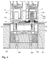
- the Fig. 4 shows a door frame 2 according to the invention on a sliding door and arranged in the bottom area spacers with height adjustment.
- the embodiment according to the Fig. 4 is substantially similar to the previous illustration of Fig. 3 or also the Fig. 2 , It differs in that 2/1 widening profiles 9/1, 9/2 are arranged below the lower frame part, which have a height adjustment 9/3 or 9/4. All other reference numerals have already been presented and are also available in Fig. 4 used in the same way, so that is renounced to a new idea.
- the Fig. 5 shows an exploded view of another embodiment of the door frame 2 according to the invention.
- the reference numeral 1 the threshold, here shown as essay threshold referred to. With 1/2 is again the thermal break and designated 1/3 the carriage rail.
- Part of the door frame 2 is in the Fig. 5 shown on the top right.
- An arrow indicates that a compensation profile 100 can be connected there.
- Below the compensation profile 100 is shown an end cap, which is glued to the end of the compensation profile, for example with PVC adhesive.
- a holding plate 110 is shown, which (not shown) can be fastened with a particular angled composite sheet 110/1 for connecting an on-site geomembrane.
- This holding plate 110 can either be attached laterally to the ground sill 1 or else to the lower frame part 2/1.
- the latter embodiment is included Not shown.
- Below the lower frame part 2/1 are widenings 8/1 and 8/2.
- the second connecting means 8/3 are shown, by means of which the widenings 8/1 and 8/2 can be fastened to the lower frame part 2/1.
- Still further below are widening profiles 9/1 and 9/2, which likewise have second connecting means 9/5, by means of which the widening profile 9/1 or 9/2 either at the widening 8/1 or 8/2 or at the lower frame part 2/1 is attachable.
- the spacers no matter whether 8 or 9, directly to the ground sill 1, if there the first connection means are provided on the bottom.
- the reference numeral 12 is still a plastic profile for wall-side connection or wall-side sealing of the threshold shown. From this exploded view it is apparent how a door frame 2 according to the invention, in particular in the region of the lower frame part 2/1 composed.
- FIG. 6a and 6b Details of the attachment of the fixed wing 3 a sliding door or lifting / sliding door on the floor sill 1 of the door frame 2 according to the invention are shown.
- an adapter 6 is screwed with a fastening screw 13 under the fixed wing 3.
- the assembly of the adapter takes place before placing the fixed wing on the ground sill 1.
- the adapter also serves to leveling the slope, which has the bottom rail 1.
- For a vertical mounting position of the fixed wing 3 is secured.
- a part of the ground sill 1 is shown, this having a predetermined bending point 1/6, which has already been described earlier.
- the fixed wing 3 is placed on the ground sill 1 and as can be seen, the slope of the ground sill 1 is compensated by the adapter 6.
- the attachment is made from above with a further fastening screw 14th
- FIG. 7a and 7b Details of the fixed and the movable sash 3, 4 are shown with the bottom sill 1 of the door frame 2 according to the invention. It is essentially about the representation of the seal between the fixed wing 3 and movable wing 4. This is in the Fig. 7a the movable wing 4 shown in its lowered position. It can clearly be seen that the sealing pads 11/1 and 11/2 cooperate sealingly. The bottom seals 10/1 and 10/2 are seated on the ground sill 1 and slightly compressed. In the Fig. 7b the movable wing 4 is shown in its raised position. It is clear that the sealing elements are lifted from the threshold and the sealing elements of the fixed wing 3, so that a smooth movement of the movable wing can be done. The movable wing is guided by at least one roller 5 on the carriage rail 1/3.
- the Fig. 8 shows details of a lifting / sliding door with threshold 1 of the door frame 2 according to the invention in a three-dimensional view. It can be seen how the fixed wing 3 a lifting / sliding door is arranged on the bottom sill 1 and how the movable wing 4, z. B. is moved to close the door to the fixed wing 3 out.
- the reference numerals have been presented in total already, so that can be dispensed with a new idea.
- the presentation of the Fig. 8 serves essentially to show the mode of operation of a lifting / sliding door in cooperation with a door frame 2 (indicated here only as a floor sill 1).
- FIGS. 9 and 10 show a cover strip 1/4 and a carriage rail 1/3 for the door frame 2 according to the invention in a sectional view. It can be seen that the side edges were beveled by 30 °. This serves, as already described above, for receiving sealants and / or adhesives for producing an adhesive bond 15.
- the Fig. 11 shows in section an embodiment of the floor sill 1 as an attachment profile for the door frame 2 according to the invention. It can be seen that the recesses 1/1 and 1/5 are intended to receive a cover 1/4 or 1/3. A thermal separation is not provided in this variant, since this threshold can be obtained, for example, as a plastic profile, which is why no thermal separation is required. In an embodiment in light metal, z. As aluminum, of course, a thermal separation is provided, as previously described above.
- the threshold 1 can be performed according to the invention in wood, if desired!
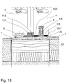
- the Fig. 12 and 13 show variants of a lifting / sliding door with a door frame 2 according to the invention, the illustration in the Fig. 12 a threshold 1, which has been obtained for example from plastic. Furthermore, the threshold 1 closes in the illustration according to Fig. 12 laterally with the edge of the lower frame profile 2/1 from. There, the prefabricated floor adjoins left and right in each case so that a barrier-free transition arises.
- Fig. 13 is a door frame with lower frame part 2/1 shown, which carries a threshold 1, for example made of aluminum profile.
- the threshold 1 made of aluminum has a thermal break 1/2 over which, for example, the carriage rail 1/3 is arranged. All other details have already been presented.
- the Fig. 14 shows a sliding door or lifting sliding door according to the invention in section, in this embodiment, a three-piece threshold 1 is connected to the lower frame part 2/1.
- the connection is made by means of clip connection, which are located between the lower frame part 2/1 and the middle part 1/10 of the bottom sill 1.
- the outwardly facing part 1/9 of the threshold is obtained in this embodiment of a metal profile, such as light metal and is, as can be seen, very well adapted to the finished floor.
- This embodiment allows in particular the favorable attachment of the seal.
- the predetermined bending point which may also be provided here, for example, at the junction between the lower frame part 2/1 and outer floor, is not shown in this embodiment.
- the middle part of the threshold carries the reference numeral 1/10 and can be made for example of plastic or fiber-reinforced plastic.
- a carriage rail 1/3 is placed in the bottom sill 1, wherein the carriage rail 1/3 carries or guides the movable sash 4.
- On the inward facing side of the third part of the three-part threshold, namely the inwardly facing part 1/8 of the threshold is arranged. This is located in a rail 1/12 and that in a provided there receiving groove 1/11.
- the fixed wing 3 shown on the left is fastened to the threshold with an adapter. The fastening means are not shown in this illustration.
- all the reference signs in the previous embodiments have already been presented, so that will not be discussed again.
- a seal is arranged here, this is usually referred to as Andichtung and here (also not shown) in a corresponding recess of the rail 1/12 or the inwardly facing part 1/8 of the threshold are attached.
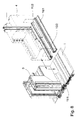
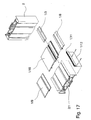
- the Fig. 15a, 15b . 16 and 17 show different views and Embodiments of a door frame in three-dimensional representation and partially designed as a so-called exploded view. It is quite clear here that the three-part threshold is arranged with the outwardly facing part 1/9, with the inwardly facing part 1/8 and with the middle part 1/10 on the lower frame part 2/1. It can be seen clearly that the vertically extending frame is notched in the region of the outwardly facing part 1/9 of the threshold to allow a dense and rich composite or a correspondingly dense resting on this part. This is shown in the illustration Fig. 16 even better visible.
- Fig. 15a the rail 1/12 is shown with the receiving groove 1/11, which receives the inward-facing part 1/8 of the frame.
- the rail 1/12 can be fastened in this embodiment by means of fastening screws on the lower frame part 2/1.
- the assembly process for the assembly of the individual frame parts and the parts of the bottom sill 1 can be seen.
- the four frame parts are usually cut to size.
- the portion of the frame or the frame extending vertically is unlatched on both sides, on which it rests on the outwardly facing part 1/9 of the threshold. This is indicated by a dashed line.
- a vertical positioning of the vertical frame member is made possible here and on the other hand a secure contact and possibly possible sealing achieved.
- the outward facing part 1/9 of the threshold is placed on the lower frame part and connected to this. Only then will be the other frame parts joined together to form an overall frame.
- the middle part 1/10 of the threshold are placed on the lower frame part and then either the, as in Fig. 16 shown integrally formed rail with the inwardly facing part of the threshold on the lower frame part 2/1 attached.
- one or more carriage rail (s) 1/3 in the middle part 1/10 of the threshold can be inserted.
- the order can be reversed chosen by first the carriage rail 1/3 is fitted and then the inwardly facing part 1/8 of the threshold is mounted.
- Fig. 17 is basically the same procedure as with Fig. 16 described, to choose.
- the rail 1/12 provided with a receiving groove 1/11, in which the inward-facing part 1/8 of the threshold can be inserted. It is done so that, for example, the rail 1/12 in the lower frame part 2/1 is then fastened when the outward-facing part 1/9 of the threshold is attached to this. Then the frame is assembled closed on four sides and then placed the middle part 1/10 of the threshold. Finally, the inward facing part 1/8 of the threshold and the carriage rail 1/3 is mounted as previously described.
Landscapes
- Engineering & Computer Science (AREA)
- Civil Engineering (AREA)
- Structural Engineering (AREA)
- Wing Frames And Configurations (AREA)
- Door And Window Frames Mounted To Openings (AREA)
- Specific Sealing Or Ventilating Devices For Doors And Windows (AREA)
Applications Claiming Priority (1)
| Application Number | Priority Date | Filing Date | Title |
|---|---|---|---|
| DE200720015160 DE202007015160U1 (de) | 2007-10-30 | 2007-10-30 | Türrahmen mit einer Bodenschwelle |
Publications (2)
| Publication Number | Publication Date |
|---|---|
| EP2055882A2 true EP2055882A2 (fr) | 2009-05-06 |
| EP2055882A3 EP2055882A3 (fr) | 2014-04-02 |
Family
ID=40282368
Family Applications (1)
| Application Number | Title | Priority Date | Filing Date |
|---|---|---|---|
| EP08016551.7A Withdrawn EP2055882A3 (fr) | 2007-10-30 | 2008-09-19 | Cadre de porte doté d'un seuil |
Country Status (2)
| Country | Link |
|---|---|
| EP (1) | EP2055882A3 (fr) |
| DE (1) | DE202007015160U1 (fr) |
Cited By (6)
| Publication number | Priority date | Publication date | Assignee | Title |
|---|---|---|---|---|
| DE102014205287A1 (de) * | 2014-03-21 | 2015-09-24 | Roto Frank Ag | Schiebefenster oder Schiebetür mit einem Dichtelement |
| CN107956372A (zh) * | 2017-12-01 | 2018-04-24 | 江苏远翔装饰工程有限公司 | 无障碍高气密性外开门 |
| CN108049792A (zh) * | 2017-12-01 | 2018-05-18 | 江苏远翔装饰工程有限公司 | 门外开纱推拉的无障碍组合门系统 |
| CN111980530A (zh) * | 2020-09-15 | 2020-11-24 | 金螳螂精装科技(苏州)有限公司 | 一种预制装配式飘窗的窗台饰面安装结构 |
| CN116639576A (zh) * | 2023-04-13 | 2023-08-25 | 通力电梯有限公司 | 通用门槛和电梯 |
| EP4506530A1 (fr) * | 2023-08-07 | 2025-02-12 | H. u. J. Steiner Gesellschaft m.b.H. | Système de rail de guidage pour un système d'élément coulissant et système d'élément coulissant |
Families Citing this family (8)
| Publication number | Priority date | Publication date | Assignee | Title |
|---|---|---|---|---|
| AT510908B1 (de) | 2010-12-22 | 2015-10-15 | Ifn Holding Ag | Blendrahmen |
| DE102015122312B4 (de) | 2015-12-18 | 2024-07-11 | Claudia Rager-Frey | Hebeschiebetür |
| DE202016101390U1 (de) * | 2016-03-13 | 2016-04-29 | Veka Ag | Mitteldichtungsblock und Mitteldichtungsblocksystem für eine Hebeschiebtür |
| CN109138739A (zh) * | 2018-08-27 | 2019-01-04 | 中船澄西船舶修造有限公司 | 一种船用可拆卸或隐藏的门槛结构 |
| DE102022206444B4 (de) | 2022-06-27 | 2024-03-07 | Profine Gmbh | Blendrahmen für eine Tür mit Extrusionsrahmen und Schwelle, Tür mit einem derartigen Blendrahmen und Verfahren zur Herstellung dieser Tür |
| DE102023204117A1 (de) * | 2023-05-04 | 2024-11-07 | Roto Frank Fenster- und Türtechnologie GmbH | Fenster oder Tür mit einem modularen Schwellensystem |
| DE102023129700A1 (de) * | 2023-10-27 | 2025-04-30 | Maco Technologie Gmbh | Bodenschwellensystem |
| DE102024131341A1 (de) | 2024-10-28 | 2026-04-30 | Profine Gmbh | Blendrahmen für eine Tür mit Extrusionsrahmen und Schwelle, Tür mit einem derartigen Blendrahmen und Verfahren zur Herstellung dieser Tür |
Family Cites Families (3)
| Publication number | Priority date | Publication date | Assignee | Title |
|---|---|---|---|---|
| DE29708214U1 (de) * | 1997-05-07 | 1998-09-10 | Niemann, Hans Dieter, 50169 Kerpen | Türrahmen |
| DE102004016079A1 (de) * | 2004-03-30 | 2005-10-20 | Schuering Gmbh & Co Fenster Te | Türschwellensystem |
| DE102005043199A1 (de) * | 2004-10-09 | 2006-05-04 | Josef Westermann | Rahmen für eine Tür, ein Fenster oder dergleichen |
-
2007
- 2007-10-30 DE DE200720015160 patent/DE202007015160U1/de not_active Expired - Lifetime
-
2008
- 2008-09-19 EP EP08016551.7A patent/EP2055882A3/fr not_active Withdrawn
Cited By (6)
| Publication number | Priority date | Publication date | Assignee | Title |
|---|---|---|---|---|
| DE102014205287A1 (de) * | 2014-03-21 | 2015-09-24 | Roto Frank Ag | Schiebefenster oder Schiebetür mit einem Dichtelement |
| CN107956372A (zh) * | 2017-12-01 | 2018-04-24 | 江苏远翔装饰工程有限公司 | 无障碍高气密性外开门 |
| CN108049792A (zh) * | 2017-12-01 | 2018-05-18 | 江苏远翔装饰工程有限公司 | 门外开纱推拉的无障碍组合门系统 |
| CN111980530A (zh) * | 2020-09-15 | 2020-11-24 | 金螳螂精装科技(苏州)有限公司 | 一种预制装配式飘窗的窗台饰面安装结构 |
| CN116639576A (zh) * | 2023-04-13 | 2023-08-25 | 通力电梯有限公司 | 通用门槛和电梯 |
| EP4506530A1 (fr) * | 2023-08-07 | 2025-02-12 | H. u. J. Steiner Gesellschaft m.b.H. | Système de rail de guidage pour un système d'élément coulissant et système d'élément coulissant |
Also Published As
| Publication number | Publication date |
|---|---|
| DE202007015160U1 (de) | 2009-03-12 |
| EP2055882A3 (fr) | 2014-04-02 |
Similar Documents
| Publication | Publication Date | Title |
|---|---|---|
| DE202007015160U1 (de) | Türrahmen mit einer Bodenschwelle | |
| EP2809864B1 (fr) | Seuil accessible aux handicapés, en particulier seuil d'une construction ancienne ou d'un logement rénové | |
| EP0937856B1 (fr) | Vantail de porte ou de fenêtre formé par un double vitrage | |
| DE102007003904B4 (de) | Bodenschwelle und Schiebetüre mit einer Bodenschwelle | |
| AT515184A1 (de) | Vorrichtung für das Verschließen einer Gebäudeöffnung | |
| EP2206871A1 (fr) | Système de profilé pour une porte coulissante | |
| WO2014167077A1 (fr) | Seuil en particulier pour passages sans obstacle | |
| EP2327854A2 (fr) | Seuil de sol et système d'élargissement et/ou d'isolation | |
| AT511951B1 (de) | Hebe/schiebetür | |
| AT516308B1 (de) | Fensterelement | |
| AT511726A1 (de) | Vorrichtung zum verschieben eines schiebeelements | |
| DE1801947A1 (de) | In einem Profilrahmen gefasste Glasscheibe insbesondere fuer Schwenk-Kippfenster,Tueren od.dgl. | |
| AT511798B1 (de) | Bodenschwelle für eine hebe/schiebetür | |
| DE102006007742A1 (de) | Bodenschwelle | |
| EP3103952A1 (fr) | Encadrement d'un element de porte coulissante ou de fenetre | |
| DE202012001082U9 (de) | Barrierefreie Bodenschwelle, insbesondere Altbau- bzw. Renovierungsschwelle | |
| AT510908B1 (de) | Blendrahmen | |
| DE102016104583A1 (de) | Profilsystem für Flügelelemente von Fassaden | |
| DE3616408C1 (de) | Verglasung fuer Gewaechshaeuser oder dergleichen sowie dabei verwendbare Glasscheibe | |
| DE8905436U1 (de) | Dachgaube | |
| DE202017101034U1 (de) | Fensterbank-Montageelement | |
| EP3064699B1 (fr) | Fenêtre ou porte et leur procédé de fabrication | |
| AT510161B1 (de) | Vorrichtung zur verbindung von wandteilen | |
| DE20009185U1 (de) | Schwellenprofil für Gebäudetüren sowie Gebäudetür | |
| AT400609B (de) | Schwellenschenkel für tür- oder fensterrahmen |
Legal Events
| Date | Code | Title | Description |
|---|---|---|---|
| PUAI | Public reference made under article 153(3) epc to a published international application that has entered the european phase |
Free format text: ORIGINAL CODE: 0009012 |
|
| AK | Designated contracting states |
Kind code of ref document: A2 Designated state(s): AT BE BG CH CY CZ DE DK EE ES FI FR GB GR HR HU IE IS IT LI LT LU LV MC MT NL NO PL PT RO SE SI SK TR |
|
| AX | Request for extension of the european patent |
Extension state: AL BA MK RS |
|
| PUAL | Search report despatched |
Free format text: ORIGINAL CODE: 0009013 |
|
| AK | Designated contracting states |
Kind code of ref document: A3 Designated state(s): AT BE BG CH CY CZ DE DK EE ES FI FR GB GR HR HU IE IS IT LI LT LU LV MC MT NL NO PL PT RO SE SI SK TR |
|
| AX | Request for extension of the european patent |
Extension state: AL BA MK RS |
|
| RIC1 | Information provided on ipc code assigned before grant |
Ipc: E06B 3/46 20060101ALI20140226BHEP Ipc: E06B 7/16 20060101ALN20140226BHEP Ipc: E06B 1/70 20060101AFI20140226BHEP |
|
| STAA | Information on the status of an ep patent application or granted ep patent |
Free format text: STATUS: THE APPLICATION IS DEEMED TO BE WITHDRAWN |
|
| 18D | Application deemed to be withdrawn |
Effective date: 20140401 |