EP2057376B1 - Pompe à membrane comprenant deux corps de membrane et deux boîtiers de pompe séparés - Google Patents
Pompe à membrane comprenant deux corps de membrane et deux boîtiers de pompe séparés Download PDFInfo
- Publication number
- EP2057376B1 EP2057376B1 EP07856361A EP07856361A EP2057376B1 EP 2057376 B1 EP2057376 B1 EP 2057376B1 EP 07856361 A EP07856361 A EP 07856361A EP 07856361 A EP07856361 A EP 07856361A EP 2057376 B1 EP2057376 B1 EP 2057376B1
- Authority
- EP
- European Patent Office
- Prior art keywords
- diaphragm
- pump
- air
- housings
- pump housing
- Prior art date
- Legal status (The legal status is an assumption and is not a legal conclusion. Google has not performed a legal analysis and makes no representation as to the accuracy of the status listed.)
- Active
Links
Images

Classifications
-
- F—MECHANICAL ENGINEERING; LIGHTING; HEATING; WEAPONS; BLASTING
- F04—POSITIVE - DISPLACEMENT MACHINES FOR LIQUIDS; PUMPS FOR LIQUIDS OR ELASTIC FLUIDS
- F04B—POSITIVE-DISPLACEMENT MACHINES FOR LIQUIDS; PUMPS
- F04B45/00—Pumps or pumping installations having flexible working members and specially adapted for elastic fluids
- F04B45/04—Pumps or pumping installations having flexible working members and specially adapted for elastic fluids having plate-like flexible members, e.g. diaphragms
- F04B45/043—Pumps or pumping installations having flexible working members and specially adapted for elastic fluids having plate-like flexible members, e.g. diaphragms two or more plate-like pumping flexible members in parallel
Definitions
- the invention relates to a diaphragm pump with two membrane heads and with two separate pump housings and membranes provided therein, wherein the pump housing are arranged adjacent to each other and the drive of the membranes is offset by 180 degrees, that the direction of the simultaneous deflections of the membranes of the two pump housings in opposite directions is.
- a metering pump which has two pumping chambers, in each of which a circumferentially clamped pumping membrane is reciprocable.
- the in the pumping chambers provided pumping membranes are such by a common drive rod back and forth that the drive of the membranes is offset by 180 ° and the direction of the simultaneous deflections of the pumping chambers located in the pumping diaphragms is in opposite directions.
- the pumping diaphragms of the metering pump intended for metering viscous media are driven by means of a pressurized gas, which can be driven by the drive rod alternately into the pumping chambers and expelled from there.
- a noise attenuation of the moving at the diaphragm underside of the membranes located in the pumping chambers air is in the US-A-4,008,984 neither intended nor addressed.
- a diaphragm pump which has two pump heads, in each of which a pumping membrane is oscillating back and forth.
- the pumping membranes is associated with a common drive motor, which is arranged in a pump housing.
- the drive motor is at the both sides projecting shaft ends of its motor shaft in each case with a crank drive in drive connection, which in turn are connected to one of the pumping diaphragms.
- a pump which has two identical separate pumping units, which are driven by a common shaft with cams.
- Each of these pumping units comprises a membrane head and a pump housing, wherein the pump housing consists of an upper housing part, a middle housing part and a lower housing part.
- the pistons provided in the membrane heads are oscillatingly movable via piston rods, which respectively protrude through the middle housing part into the interior of the housing.
- the piston rods assigned to the membrane heads should project in a sealed manner through the central housing parts into the interior of the housing.
- the subject of claim 1 is in two-part form over de disclosure of this document.
- the membrane pump defined at the outset is characterized in that the two pump housings are connected to one another so that the air displaced by one diaphragm pump can be moved into the other pump housing in which the associated diaphragm is due to the opposite drive a room enlargement leads.
- This ensures that the moving of the membranes in the pump housings air does not have to escape or only to a small extent into the open, because the displaced from the one membrane air can flow into the other pump housing, if the diaphragm just the inner volume of this second pump housing increased.
- the respective displaced air can thus be moved back and forth between the two closed pump housings.
- these can be compared to the environment be made airtight or largely airtight.
- At least one connecting line is provided between the two substantially parallel pump housings arranged at least one connecting line and if the cross-section and / or the flow resistance of the connecting line or connecting lines is dimensioned such that at least a part or all of the diaphragm underside promoted or displaced Air in the other pump housing is conveyed.
- a particularly simple air-permeable connection so at least one connecting line for the reciprocating air is provided, so that the construction of the diaphragm pump and its separate pump housing can remain unchanged and only a corresponding connection line is provided.
- the connecting line can in particular connect the mutually facing sides or walls of the two pump housings in a straight line. This is practically the shortest connection for the air line, so that their flow resistance is correspondingly low. In addition, in the immediate space between the two pump housings usually enough unused space to accommodate such a connection line can.
- the two separate pump housings and / or the delivery volume of the two membranes arranged therein per stroke can expediently be the same. Then there is the best possible compensation of the respective displaced air from one to the other pump housing and back again.
- one bearing disc covering the bearing can be provided on the bearing of the drive shaft in the region of the passage through the pump housing.
- Felt washers are effective sealants that cause little or no noise.
- the felt disk on the inside of the pump housing facing away and / or facing side of the bearing or ball bearing be mounted. This may be dependent on the particular construction of the support of the drive shaft become.
- the respective pump housing in the region of the connecting rod for the drive of the diaphragm has an intermediate wall for delimiting the crankcase from the movement space of the diaphragm head, which has a passage opening for the connecting rod, and that the connection or connecting line of the two Pump housing is provided in particular between this intermediate wall and the underside of the respective Membranköpfs. Also by the moving of the membranes or diaphragm heads within the pump housing air is mainly or exclusively directed into the connecting line and thus the risk of leakage of air from the pump housings further reduced or avoided.
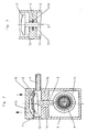
- a designated as a whole with 1 diaphragm pump has two membranes 6 and two separate, adjacent to each other arranged pump housing 3 and two membrane heads 15, wherein a common drive shaft 4, the connecting rod 5 of the two membranes 6 drives.
- the drive of the two membranes 6 or of these supporting connecting rods 2, as in Fig.1 clearly shown, offset by 180 degrees, that the direction of the simultaneous deflections of the membranes 6 of the two connecting rods 2 in each case in opposite directions.
- Fig.1 clearly that the connecting rod shown on the left 2 with the diaphragm 6 has just reached the top position, while the other connecting rod 2 has reached with its diaphragm 6 according to the offset of the drive by 180 degrees, the opposite position, namely the bottom position.
- the connecting rod 2 is at top dead center, the other connecting rod 2 has reached the bottom dead center, which constantly changes during operation of the diaphragm pump 1.
- the two pump housing 3 are connected by air permeable to each other by means of a connecting line 7, so that the displaced by the downwardly moving connecting rod 2 air can be conveyed through this connecting line 7 in the other pump housing 3, where the upward movement of the connecting rod 2 straight to an increase in the volume of air within the pump housing 3 leads, so that a constant exchange of the respective displaced and required amounts of air between the two pump housings 3 via the connecting line 7 is possible.
- the air displaced in each case by the connecting rod fungi 2 and the membranes 6 does not need to escape from the pump housings 3, so that no noise development caused by such an air outlet occurs he follows.
- connection line 7 provided between the two pump housings 3 arranged substantially parallel to one another and also their flow resistance are dimensioned such that as far as possible the entire air conveyed or displaced by the respective diaphragm underside is conveyed into the respective other pump housing 3.
- connection line 7 rectilinearly connects the two pump housings 3 to the mutually facing sides or walls 3a, so that the shortest possible connecting line 7 is possible, which may be flexible or else rigid, in order to connect the two pump housings 3 stably at the same time ,
- Fig.1 is also shown that in the region of the bearing or passage opening for the entire drive shaft 4 at the respective pump housing 3 at least one seal 8 is provided whose flow resistance is greater than that of the connecting line 7 between the two pump housings 3, which additionally contributes to that the underside of each of the connecting rods 2 and the membranes 6 displaced air is almost completely reciprocated via the connecting line 7 and forth.
- each one bearing 9 covering felt disk may be provided as a seal 8, which is mounted in the embodiment on the inside of the respective pump housing 3 opposite side of the bearing or ball bearing 9. But it could also be provided on the inside of the pump housing 3 side facing or on both sides of the respective bearing.
- Fig.2 and 3 is shown as an additional measure for the most exclusive promotion of each displaced air through the connecting line 7 that the respective pump housing 3 in the area of the connecting rod 5 has an intermediate wall 10 for delimiting the crankcase 11 of the movement space 12 of the diaphragm 6, wherein a passage opening 13 for the connecting rod 5 is necessary and provided and the connecting line of the two pump housing 3 between this intermediate wall 10 and the underside of the respective connecting rod 2 is arranged.
- the intermediate wall and the narrowest possible passage opening 13 improve the conveying of displaced at the bottom of the respective connecting rod mushroom in the downward movement of air into and through the connecting line. 7
- the diaphragm pump 1 has two membrane heads 15, two diaphragms each 6 and two separate pump housing 3, in which the connecting rods 5 are arranged with connecting rods 2 for the membranes 6, which can be driven by a common shaft 4, wherein the drive for the shaft 4th can be arranged between the two pump housings 3.
- the two pump housing 3 are air-permeable, in particular via a connecting line 7 connected to each other, so that each displaced by the one diaphragm 6 air can be moved into the other pump housing 3, in which the associated diaphragm 6 leads to an increase in space due to the opposite drive.
Landscapes
- Engineering & Computer Science (AREA)
- Mechanical Engineering (AREA)
- General Engineering & Computer Science (AREA)
- Reciprocating Pumps (AREA)
Claims (9)
- Pompe (1) à membranes comprenant deux têtes (15) de membranes, ainsi que deux carters de pompage distincts (3) et des membranes (6) prévues dans ces derniers, lesdits carters de pompage (3) étant disposés au voisinage l'un de l'autre, et l'entraînement des membranes (6) présentant un décalage réciproque de 180 degrés, de telle sorte que la direction des excursions simultanées desdites membranes (6) des deux carters de pompage (3) pointe dans des sens respectivement opposés, caractérisée par le fait que les deux carters de pompage (3) sont reliés l'un à l'autre avec perméabilité à l'air de façon telle que l'air, respectivement refoulé par l'une (6) des membranes, puisse être mis en mouvement jusque dans l'autre carter de pompage (3) dans lequel, du fait de l'entraînement en sens inverses, la membrane associée (6) provoque un accroissement de l'espace.
- Pompe à membranes selon la revendication 1, caractérisée par le fait qu'au moins un conduit de jonction (7) est prévu en tant que liaison, perméable à l'air, entre les deux carters de pompage (3) disposés pour l'essentiel parallèlement l'un à l'autre ; et par le fait que la section transversale et/ou la résistance à l'écoulement dudit conduit de jonction (7), ou des conduits de jonction, est (sont) dimensionnée(s) de telle sorte qu'au moins une partie, ou la totalité de l'air charrié ou refoulé par la face inférieure des membranes, puisse être convoyée jusque dans le carter de pompage (3) respectivement autre.
- Pompe à membranes selon la revendication 2, caractérisée par le fait que le conduit de jonction (7) relie, notamment en ligne droite, les faces ou parois (3a) des deux carters de pompage (3) qui sont tournées les unes vers les autres.
- Pompe à membranes selon l'une des revendications 1 à 3, caractérisée par le fait que les deux carters de pompage (3), et/ou le volume refoulé par les deux membranes (6), sont de dimensionnements identiques lors de chaque course.
- Pompe à membranes selon l'une des revendications 1 à 4, caractérisée par le fait qu'au moins une garniture d'étanchement (8), dont la résistance à l'écoulement est supérieure à celle du conduit de jonction (7) entre les deux carters de pompage (3), est prévue sur le carter de pompage (3) considéré, dans la région de l'orifice de portée et de passage dédié à l'arbre d'entraînement (4) notamment commun.
- Pompe à membranes selon l'une des revendications 1 à 5, caractérisée par le fait qu'un disque respectif en feutre est prévu en tant que garniture d'étanchement (8) au niveau du palier (9) de l'arbre d'entraînement (4), dans la région du passage à travers les carters de pompage, et recouvre ledit palier (9).
- Pompe à membranes selon la revendication 6, caractérisée par le fait que le disque en feutre est implanté sur la face du palier ou du roulement à billes (9) qui est tournée à l'opposé de l'espace interne du carter de pompage (3), et/ou vers ledit espace interne.
- Pompe à membranes selon l'une des revendications 1 à 7, caractérisée par le fait que le carter de pompage (3) considéré présente, dans la région de la bielle (5), une cloison intermédiaire (10) qui est conçue pour délimiter le carter de manivelle (11) par rapport à l'espace (12) de mouvement de la tête (15) de la membrane, et est percée d'un orifice de passage (13) dédié à ladite bielle (5) ; et par le fait que la liaison perméable à l'air, ou le conduit (7) de jonction des deux carters de pompage (3), est notamment prévu(e) entre cette cloison intermédiaire (10) et la face inférieure de la tête (15) de membrane considérée.
- Pompe à membranes selon la revendication 8, caractérisée par le fait que l'orifice de passage (13), pratiqué dans la cloison intermédiaire (10) et dédié à la bielle (5), présente une tolérance serrée vis-à-vis de cette dernière et/ou renferme une garniture d'étanchement (14) ou un disque en feutre sollicitant ladite bielle (5), et autorisant le mouvement de celle-ci.
Applications Claiming Priority (2)
| Application Number | Priority Date | Filing Date | Title |
|---|---|---|---|
| DE102007003720A DE102007003720B3 (de) | 2007-01-25 | 2007-01-25 | Membranpumpe mit zwei Membranköpfen und zwei separaten Pumpengehäusen |
| PCT/EP2007/010520 WO2008089813A1 (fr) | 2007-01-25 | 2007-12-04 | Pompe à membrane comprenant deux corps de membrane et deux boîtiers de pompe séparés |
Publications (2)
| Publication Number | Publication Date |
|---|---|
| EP2057376A1 EP2057376A1 (fr) | 2009-05-13 |
| EP2057376B1 true EP2057376B1 (fr) | 2012-11-28 |
Family
ID=39154052
Family Applications (1)
| Application Number | Title | Priority Date | Filing Date |
|---|---|---|---|
| EP07856361A Active EP2057376B1 (fr) | 2007-01-25 | 2007-12-04 | Pompe à membrane comprenant deux corps de membrane et deux boîtiers de pompe séparés |
Country Status (5)
| Country | Link |
|---|---|
| US (1) | US20100316512A1 (fr) |
| EP (1) | EP2057376B1 (fr) |
| CN (1) | CN101680443A (fr) |
| DE (1) | DE102007003720B3 (fr) |
| WO (1) | WO2008089813A1 (fr) |
Families Citing this family (5)
| Publication number | Priority date | Publication date | Assignee | Title |
|---|---|---|---|---|
| CN103147965B (zh) * | 2013-03-11 | 2015-07-22 | 浙江奥利达气动工具股份有限公司 | 单级多头隔膜式气泵 |
| CN103244394A (zh) * | 2013-05-10 | 2013-08-14 | 北京京城压缩机有限公司 | 一种单缸盖的隔膜式压缩机集成缸体部件 |
| US10697447B2 (en) * | 2014-08-21 | 2020-06-30 | Fenwal, Inc. | Magnet-based systems and methods for transferring fluid |
| CN104564623B (zh) * | 2015-01-14 | 2017-02-22 | 厦门坤锦电子科技有限公司 | 一种带有双隔膜的微型水泵 |
| CN112696341A (zh) * | 2020-12-21 | 2021-04-23 | 深圳安吉尔饮水产业集团有限公司 | 隔膜增压泵的泵头、隔膜增压泵、水处理装置 |
Citations (1)
| Publication number | Priority date | Publication date | Assignee | Title |
|---|---|---|---|---|
| DE2446805A1 (de) * | 1974-10-01 | 1976-04-08 | Ott Kg Lewa | Pulsationsfrei arbeitende dosierpumpe |
Family Cites Families (12)
| Publication number | Priority date | Publication date | Assignee | Title |
|---|---|---|---|---|
| US2285215A (en) * | 1939-06-08 | 1942-06-02 | Binks Mfg Co | Fluid compressor |
| US2748606A (en) * | 1951-11-30 | 1956-06-05 | Cornelius Co | Mechanical movement |
| US2819013A (en) * | 1953-08-13 | 1958-01-07 | Cline Electric Mfg Co | Diaphragm compressor pump |
| US3734579A (en) * | 1970-12-09 | 1973-05-22 | G Schumacher | Bearing housing assembly |
| US4008984A (en) | 1975-10-23 | 1977-02-22 | Scholle William R | Pump apparatus |
| DE3046028A1 (de) * | 1980-12-06 | 1982-07-15 | LuK Lamellen und Kupplungsbau GmbH, 7580 Bühl | Membranpumpe |
| DE9317083U1 (de) | 1993-11-09 | 1994-01-13 | Knf-Neuberger Gmbh, 79112 Freiburg | Pumpe mit einem Antriebsmotor und einem Gehäuse |
| DE4443778A1 (de) * | 1994-12-08 | 1996-06-20 | Abel Gmbh & Co | Doppelmembranpumpe |
| US6443713B1 (en) * | 2000-10-18 | 2002-09-03 | Thomas Industries Inc. | Diaphragm pump with support ring |
| DE10212239A1 (de) * | 2002-03-19 | 2003-10-09 | Knf Neuberger Gmbh | Pumpe |
| US6865981B2 (en) * | 2003-03-11 | 2005-03-15 | Ingersoll-Rand Company | Method of producing a pump |
| US20090068032A1 (en) * | 2005-05-10 | 2009-03-12 | Pendotech | Sanitary Diaphragm Pump for Critical Bioprocess Applications |
-
2007
- 2007-01-25 DE DE102007003720A patent/DE102007003720B3/de not_active Expired - Fee Related
- 2007-12-04 US US12/521,682 patent/US20100316512A1/en not_active Abandoned
- 2007-12-04 CN CN200780046828A patent/CN101680443A/zh active Pending
- 2007-12-04 WO PCT/EP2007/010520 patent/WO2008089813A1/fr not_active Ceased
- 2007-12-04 EP EP07856361A patent/EP2057376B1/fr active Active
Patent Citations (1)
| Publication number | Priority date | Publication date | Assignee | Title |
|---|---|---|---|---|
| DE2446805A1 (de) * | 1974-10-01 | 1976-04-08 | Ott Kg Lewa | Pulsationsfrei arbeitende dosierpumpe |
Also Published As
| Publication number | Publication date |
|---|---|
| CN101680443A (zh) | 2010-03-24 |
| EP2057376A1 (fr) | 2009-05-13 |
| DE102007003720B3 (de) | 2008-08-21 |
| US20100316512A1 (en) | 2010-12-16 |
| WO2008089813A1 (fr) | 2008-07-31 |
Similar Documents
| Publication | Publication Date | Title |
|---|---|---|
| EP2761180B1 (fr) | Pompe volumétrique | |
| EP0604740B1 (fr) | Pompe à membrane | |
| EP4328448B1 (fr) | Pompe à membrane | |
| EP2057376B1 (fr) | Pompe à membrane comprenant deux corps de membrane et deux boîtiers de pompe séparés | |
| DE102008040574B4 (de) | Kolbenmaschine | |
| DE102012109634A1 (de) | Kolben-Membranpumpe | |
| DE102008062483A1 (de) | Axialkolbenmaschine mit Pulsationsminderung | |
| DE69926666T2 (de) | Pumpe | |
| DE68907576T2 (de) | Verdrängerpumpe. | |
| DE102006016791B4 (de) | Vakuumpumpe | |
| DE102014010108A1 (de) | Hydraulisch angetriebene Membranpumpe | |
| WO2008080492A1 (fr) | Pompe à vide avec une soupape de sortie | |
| DE202007001117U1 (de) | Membranpumpe mit zwei Membranköpfen und zwei separaten Pumpengehäusen | |
| DE102008031450A1 (de) | Pumpe | |
| EP3441612A1 (fr) | Unité de pompe, dispositif de stockage équipé d'une telle unité de pompe et procédé de fonctionnement dudit dispositif de stockage | |
| DE2102957C3 (de) | Pumpe | |
| DE102008022604A1 (de) | Kreuzkolbenverdichter | |
| WO2007115544A1 (fr) | Pompe cellulaire | |
| DE102014103459A1 (de) | Membranpumpe | |
| DE4325282A1 (de) | Vakuumpumpe mit Zusatzeinrichtung | |
| DE102011054073A1 (de) | Betriebsverfahren einer Kolben-Membranpumpe sowie Kolben-Membranpumpe | |
| EP1612421B1 (fr) | Compresseur à basse pression | |
| DE102011054074A1 (de) | Verdrängerpumpe | |
| DE202023104441U1 (de) | Doppelkolbenpumpvorrichtung | |
| CH346434A (de) | Axialkolbenpumpe mit variabler Fördermenge |
Legal Events
| Date | Code | Title | Description |
|---|---|---|---|
| PUAI | Public reference made under article 153(3) epc to a published international application that has entered the european phase |
Free format text: ORIGINAL CODE: 0009012 |
|
| 17P | Request for examination filed |
Effective date: 20081220 |
|
| AK | Designated contracting states |
Kind code of ref document: A1 Designated state(s): AT BE BG CH CY CZ DE DK EE ES FI FR GB GR HU IE IS IT LI LT LU LV MC MT NL PL PT RO SE SI SK TR |
|
| AX | Request for extension of the european patent |
Extension state: AL BA HR MK RS |
|
| 17Q | First examination report despatched |
Effective date: 20090703 |
|
| RBV | Designated contracting states (corrected) |
Designated state(s): CH DE FR GB IT LI |
|
| GRAC | Information related to communication of intention to grant a patent modified |
Free format text: ORIGINAL CODE: EPIDOSCIGR1 |
|
| GRAP | Despatch of communication of intention to grant a patent |
Free format text: ORIGINAL CODE: EPIDOSNIGR1 |
|
| DAX | Request for extension of the european patent (deleted) | ||
| GRAS | Grant fee paid |
Free format text: ORIGINAL CODE: EPIDOSNIGR3 |
|
| GRAA | (expected) grant |
Free format text: ORIGINAL CODE: 0009210 |
|
| AK | Designated contracting states |
Kind code of ref document: B1 Designated state(s): CH DE FR GB IT LI |
|
| REG | Reference to a national code |
Ref country code: GB Ref legal event code: FG4D Free format text: NOT ENGLISH |
|
| REG | Reference to a national code |
Ref country code: CH Ref legal event code: EP |
|
| REG | Reference to a national code |
Ref country code: DE Ref legal event code: R096 Ref document number: 502007010963 Country of ref document: DE Effective date: 20130124 |
|
| REG | Reference to a national code |
Ref country code: CH Ref legal event code: PL |
|
| PG25 | Lapsed in a contracting state [announced via postgrant information from national office to epo] |
Ref country code: IT Free format text: LAPSE BECAUSE OF FAILURE TO SUBMIT A TRANSLATION OF THE DESCRIPTION OR TO PAY THE FEE WITHIN THE PRESCRIBED TIME-LIMIT Effective date: 20121128 |
|
| PLBE | No opposition filed within time limit |
Free format text: ORIGINAL CODE: 0009261 |
|
| STAA | Information on the status of an ep patent application or granted ep patent |
Free format text: STATUS: NO OPPOSITION FILED WITHIN TIME LIMIT |
|
| PG25 | Lapsed in a contracting state [announced via postgrant information from national office to epo] |
Ref country code: CH Free format text: LAPSE BECAUSE OF NON-PAYMENT OF DUE FEES Effective date: 20121231 Ref country code: LI Free format text: LAPSE BECAUSE OF NON-PAYMENT OF DUE FEES Effective date: 20121231 |
|
| 26N | No opposition filed |
Effective date: 20130829 |
|
| REG | Reference to a national code |
Ref country code: DE Ref legal event code: R097 Ref document number: 502007010963 Country of ref document: DE Effective date: 20130829 |
|
| REG | Reference to a national code |
Ref country code: FR Ref legal event code: PLFP Year of fee payment: 9 |
|
| REG | Reference to a national code |
Ref country code: FR Ref legal event code: PLFP Year of fee payment: 10 |
|
| REG | Reference to a national code |
Ref country code: FR Ref legal event code: PLFP Year of fee payment: 11 |
|
| P01 | Opt-out of the competence of the unified patent court (upc) registered |
Effective date: 20230601 |
|
| PGFP | Annual fee paid to national office [announced via postgrant information from national office to epo] |
Ref country code: GB Payment date: 20251218 Year of fee payment: 19 |
|
| PGFP | Annual fee paid to national office [announced via postgrant information from national office to epo] |
Ref country code: FR Payment date: 20251218 Year of fee payment: 19 |
|
| PGFP | Annual fee paid to national office [announced via postgrant information from national office to epo] |
Ref country code: DE Payment date: 20251223 Year of fee payment: 19 |