EP2058506A2 - Nettoyeur d'air de moteur et dispositif de montage de nettoyage d'air sur un moteur - Google Patents
Nettoyeur d'air de moteur et dispositif de montage de nettoyage d'air sur un moteur Download PDFInfo
- Publication number
- EP2058506A2 EP2058506A2 EP09002663A EP09002663A EP2058506A2 EP 2058506 A2 EP2058506 A2 EP 2058506A2 EP 09002663 A EP09002663 A EP 09002663A EP 09002663 A EP09002663 A EP 09002663A EP 2058506 A2 EP2058506 A2 EP 2058506A2
- Authority
- EP
- European Patent Office
- Prior art keywords
- cover body
- cleaner
- engine
- suction opening
- air cleaner
- Prior art date
- Legal status (The legal status is an assumption and is not a legal conclusion. Google has not performed a legal analysis and makes no representation as to the accuracy of the status listed.)
- Granted
Links
- 238000004140 cleaning Methods 0.000 claims abstract description 17
- 230000003014 reinforcing effect Effects 0.000 claims description 11
- 238000012856 packing Methods 0.000 abstract description 76
- 238000012423 maintenance Methods 0.000 description 5
- 230000002093 peripheral effect Effects 0.000 description 5
- XLYOFNOQVPJJNP-UHFFFAOYSA-N water Substances O XLYOFNOQVPJJNP-UHFFFAOYSA-N 0.000 description 5
- 230000000694 effects Effects 0.000 description 4
- 230000013011 mating Effects 0.000 description 3
- 241001247986 Calotropis procera Species 0.000 description 2
- 230000002708 enhancing effect Effects 0.000 description 2
- 239000000446 fuel Substances 0.000 description 2
- 239000002828 fuel tank Substances 0.000 description 2
- 238000011144 upstream manufacturing Methods 0.000 description 2
- JOYRKODLDBILNP-UHFFFAOYSA-N Ethyl urethane Chemical compound CCOC(N)=O JOYRKODLDBILNP-UHFFFAOYSA-N 0.000 description 1
- 230000000903 blocking effect Effects 0.000 description 1
- 239000002184 metal Substances 0.000 description 1
- 239000000203 mixture Substances 0.000 description 1
- 238000012986 modification Methods 0.000 description 1
- 230000004048 modification Effects 0.000 description 1
- 230000000149 penetrating effect Effects 0.000 description 1
- 230000001737 promoting effect Effects 0.000 description 1
- 229920003002 synthetic resin Polymers 0.000 description 1
- 239000000057 synthetic resin Substances 0.000 description 1
Images








Classifications
-
- F—MECHANICAL ENGINEERING; LIGHTING; HEATING; WEAPONS; BLASTING
- F02—COMBUSTION ENGINES; HOT-GAS OR COMBUSTION-PRODUCT ENGINE PLANTS
- F02M—SUPPLYING COMBUSTION ENGINES IN GENERAL WITH COMBUSTIBLE MIXTURES OR CONSTITUENTS THEREOF
- F02M35/00—Combustion-air cleaners, air intakes, intake silencers, or induction systems specially adapted for, or arranged on, internal-combustion engines
- F02M35/02—Air cleaners
- F02M35/024—Air cleaners using filters, e.g. moistened
-
- F—MECHANICAL ENGINEERING; LIGHTING; HEATING; WEAPONS; BLASTING
- F02—COMBUSTION ENGINES; HOT-GAS OR COMBUSTION-PRODUCT ENGINE PLANTS
- F02M—SUPPLYING COMBUSTION ENGINES IN GENERAL WITH COMBUSTIBLE MIXTURES OR CONSTITUENTS THEREOF
- F02M35/00—Combustion-air cleaners, air intakes, intake silencers, or induction systems specially adapted for, or arranged on, internal-combustion engines
- F02M35/02—Air cleaners
- F02M35/04—Air cleaners specially arranged with respect to engine, to intake system or specially adapted to vehicle; Mounting thereon ; Combinations with other devices
-
- F—MECHANICAL ENGINEERING; LIGHTING; HEATING; WEAPONS; BLASTING
- F02—COMBUSTION ENGINES; HOT-GAS OR COMBUSTION-PRODUCT ENGINE PLANTS
- F02M—SUPPLYING COMBUSTION ENGINES IN GENERAL WITH COMBUSTIBLE MIXTURES OR CONSTITUENTS THEREOF
- F02M35/00—Combustion-air cleaners, air intakes, intake silencers, or induction systems specially adapted for, or arranged on, internal-combustion engines
- F02M35/10—Air intakes; Induction systems
- F02M35/1015—Air intakes; Induction systems characterised by the engine type
- F02M35/1017—Small engines, e.g. for handheld tools, or model engines; Single cylinder engines
-
- Y—GENERAL TAGGING OF NEW TECHNOLOGICAL DEVELOPMENTS; GENERAL TAGGING OF CROSS-SECTIONAL TECHNOLOGIES SPANNING OVER SEVERAL SECTIONS OF THE IPC; TECHNICAL SUBJECTS COVERED BY FORMER USPC CROSS-REFERENCE ART COLLECTIONS [XRACs] AND DIGESTS
- Y10—TECHNICAL SUBJECTS COVERED BY FORMER USPC
- Y10T—TECHNICAL SUBJECTS COVERED BY FORMER US CLASSIFICATION
- Y10T29/00—Metal working
- Y10T29/53—Means to assemble or disassemble
- Y10T29/53443—Means to assemble or disassemble container and fluid component
Definitions
- the present invention relates to an air cleaner that prevents raindrops running down an outer face of a cleaner cover body provided on an engine, particularly a general purpose engine, from being sucked therein, and that prevents outside air that has been taken in from being taken into the engine side without being cleaned. Also, the present invention relates to a device for mounting an air cleaner on an engine, in order to clean and guide outside air into an engine, particularly a general purpose engine.
- the air cleaner is supported on the engine via the carburetor in an overhanging state at a position distant from the engine, leading to a problem that it is difficult to guarantee rigidity for supporting the air cleaner.
- the capacity of a cleaner chamber is increased in order to enhance the performance of the air cleaner, the cleaner cover becomes large and the above-mentioned problem becomes more significant, resulting in a case where the cleaner cover is required to be detached beforehand in order to secure the air cleaner to the engine, thus providing another problem that the efficiency of securing the air cleaner to the engine is degraded.
- the present invention has been accomplished under the above-mentioned circumstances, and it is an object thereof to provide a novel engine air cleaner and a device for mounting the air cleaner on an engine that can solve all the above-mentioned problems.
- a boss having a hollow cylindrical hole extending toward the engine is formed integrally with the reinforcing vertical wall portion of the lower cover body; and said other securing member fixed to the engine runs through and is fixed to the hollow cylindrical hole of the lower cover body.
- the air cleaner can be secured to and supported on the engine at three points and, in particular, the cleaner cover body is secured to the engine by utilizing the high-rigidity reinforcing vertical wall of the cleaner cover body, it is possible to enhance rigidity for supporting the air cleaner on the engine.
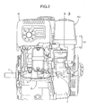
- a general purpose engine E which is a power source for various types of work machine, of a general purpose engine unit is a four-cycle engine, and includes a crankcase 2 supporting a horizontally disposed crankshaft 1 and a cylinder part 3 projecting obliquely upward from the crankcase 2.
- a fuel tank T is disposed immediately above and supported on the crankcase 2.
- a carburetor 4 is mounted on one side of the cylinder part 3.
- An air cleaner AC connected to the carburetor 4 and an exhaust muffler M connected to the other side of the cylinder part 3 are disposed immediately above the cylinder part 3 so as to be arranged in a line to the side of the fuel tank T.
- a cleaner cover body 10 which is an outer shell of the air cleaner AC, is made of a synthetic resin and is formed by integrally joining an upper cover body 11 and a lower cover body 12.
- the upper cover 11 is formed into a cap shape having a lower open face.
- the lower cover body 12 is formed in a hermetically sealed manner from an intake duct 13 formed into an elbow shape that is long in the vertical direction, and a dividing wall 14 closing the upper open face of the intake duct 13.
- An upper face of the lower cover body 12 is hermetically fitted into and detachably connected to the lower open face of the upper cover body 11.
- a rectangular tube-shaped intake passage 17 is provided integrally with a middle section of the dividing wall 14 so as to project toward the interior of the upper cover body 11, and the interior of the upper cover body 11 and the interior of the lower cover body 12 communicate with each other via the intake passage 17.
- a vertically extending supporting bolt 18 is fixed to an upper part of the intake duct 13 of the lower cover body 12. This supporting bolt 18 passes through the intake passage 17 and passes vertically through the interior of the upper cover body 11.
- a threaded portion of the upper end of the supporting bolt 18 projects outward through a mounting hole 19 provided in an upper wall of the upper cover body.
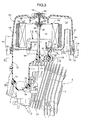
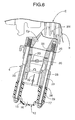
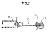
- the air cleaner AC has its lower cover body 12 supported on the cylinder part 3 of the engine E at three points. Specifically, as shown in FIGS. 3 and 6 , a lower end portion of the lower cover body 12 is supported, via the carburetor 4, on the cylinder part 3 of the engine E at two points by two connecting bolts 22 and 23; and as shown in FIGS. 3 , 5 and 7 , an upper end portion, that is, a portion close to the dividing wall 14, of the lower cover body 12 is supported directly on the cylinder part 3 of the engine E at one point by one connecting bolt 24. As shown in FIG.
- the downstream side of the carburetor 4 is connected to a cylinder head section 3H of the cylinder part 3 of the engine E via a gasket 25, and the lower end portion of the lower cover body 12 is connected integrally to the upstream side of the carburetor 4 with a packing 26 interposed therebetween-
- the lower end portion of the lower cover body 12 is secured by the two connecting bolts 22 and 23 running through bolt holes 27 and 28 provided in the lower cover body 12 and the carburetor 4 and screwed into the cylinder head section 3H of the cylinder part 3.
- a metal sleeve 29 is fitted into the bolt hole 27 of the lower cover body 12 so that the lower cover body 12 is not deformed by tightening of the connecting bolts 22 and 23.
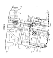
- a tubular boss 38 is formed integrally with a high-rigidity vertical wall portion 37, which is an upper end portion close to the dividing wall 14, of the lower cover body 12 of the air cleaner AC.
- a long bottomed hollow cylindrical hole 39 extending toward the interior of the lower cover body 12, that is, the cylinder part 3 of the engine E.
- a bolt hole 40 is penetratingly provided in a bottom wall of this hollow cylindrical hole 39.
- a bolt thread hole 41 is provided in a wall face, facing the bolt hole 40, of the cylinder head section 3H of the cylinder part 3, and as shown in FIG. 5 , the bolt hole 40 and the bolt thread hole 41 are on the same axis.
- a stud bolt 24 as the connecting bolt is screwed into the bolt thread hole 41.
- This stud bolt 24 runs through the bolt hole 40 of the lower cover body 12 and then its threaded portion projects into the interior of the hollow cylindrical hole 39.
- the upper part of the lower cover body 12 can be fixed to the cylinder head section 3H of the cylinder part 3 by means of this one connecting bolt 24. Therefore, in the upper part of the lower cover body 12, its high rigidity vertical wall portion 37 (being in the vicinity of the dividing wall 14 and reinforced by the boss 38) is firmly fixed to the cylinder part 3 of the engine E by the connecting bolt 24.
- the boss 38 includes the hollow cylindrical hole 39, which is deep in the direction toward the cylinder part 3, to thereby reduce the tightening distance required by the connecting bolt 24. Therefore, it is possible to make the air cleaner AC be close to the cylinder part 3, which is a mounting section on the engine side, and fixedly support the air cleaner AC thereon, thus further enhancing the rigidity for supporting the air cleaner AC.
- a cleaner element unit Ue which is described later, is detachably housed within the upper cover body 11 of the air cleaner AC.
- a rectangular tube-shaped intake tube 51 extending toward the interior of the upper cover body 11.
- This intake tube 51 is formed into a chimney shape that is gradually narrowed from an entrance on the intake opening 50 side toward an exit at the upper end thereof.
- the lower end of a skirt wall 11 a, in the vicinity of the suction opening 50, of the upper cover body 11 extends further downward than the suction opening 50, its extended portion extends so as to face the shielding wall 53 and be arranged side by side with the shielding wall 53, and the lower end of the extended portion is at substantially the same level as the lower end of the shielding wall 53.
- the shielding wall 53 and the skirt wall 11 a of the upper cover body 11 face each other to form a double wall beneath the outer open edge of the suction opening 50, and a gap 54 opening downward is formed therebetween.
- the double wall is formed by the skirt wall 11 a of the upper cover body 11 and the shielding wall 53, which cover the suction opening 50 and extend further downward than the suction opening 50, although raindrops that have been drawn toward the suction opening 50 in spite of the above-mentioned (1) flow into the gap 54 while going around the lower edge of the skirt wall 11a, here the raindrops can be made to collide with the shielding wall 53 and drop, thereby yet more reliably preventing raindrops from being sucked into the suction opening 50.
- the cleaner element unit Ue is supported and housed within the upper cover body 11 of the cleaner cover body 10.
- This cleaner element unit Ue is formed into an overall elliptical tubular shape, as shown in FIGS. 3 and 8 , comprising a cleaner element 60, a metallic upper plate 63, and a metallic lower plate 64.
- the cleaner element 60 is formed by layering a paper cleaner 62 and a urethane cleaner 61 in an elliptical tubular shape having upper and lower open faces.
- the upper plate 63 and the lower plate 64 are mounted so as to close the upper and lower open faces of the cleaner element 60.
- a mounting hole 66 is provided in a central area of the upper plate 63, a rubber bush 65 being fitted into the mounting hole 66.
- a mating hole 67 opens in a central area of the lower plate 64, the mating hole 67 being detachably fitted onto the rectangular tube-shaped air passage 17 projectingly provided on the dividing wall 14.
- the seal packing 68 which is a rubber packing, is held between the upper face of the dividing wall 14 and the lower face of the lower plate 64 of the cleaner element unit Ue.
- This seal packing 68 makes a hermetic seal between the uncleaned chamber Cd and the cleaned chamber Cc, thus preventing uncleaned outside air from being sucked directly into the cleaned chamber Cc.
- the seal packing 68 is formed into an endless rectangular shape and is fitted around the outer periphery of a base portion of the rectangular tube-shaped intake passage 17.
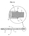
- Upper and lower lip pieces 72 and 74 having a triangular cross-section are projectingly provided integrally with a middle section, in the width direction, of an upper seal face 71 and a lower seal face 73 of the seal packing 68.
- the upper lip piece 72 is in intimate contact with the lower face of the lower plate 64 of the cleaner element unit Ue.
- the lower lip piece 74 is in intimate contact with the upper face of the dividing wall 14.
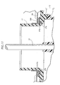
- a plurality of retaining projections 75 as retaining members are provided integrally with the inner periphery of the seal packing 68 so as to project inwardly, the retaining projections 75 being spaced in the peripheral direction of the seal packing 68.
- Embodiment 2 is slightly different from the above-mentioned embodiment in the structure of a seal packing 268, which is a rubber packing, held between the upper face of the dividing wall 14 and the lower face of the lower plate 64 of the cleaner element unit Ue, and in the structure of a mounting section for the seal packing 268.
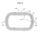
- the seal packing 268 is formed into an endless rectangular shape, and is fitted around the outer periphery of the base portion of the rectangular tube-shaped intake passage 17 in the same manner as in Embodiment 1.
- Upper and lower lip pieces 272 and 274 having a triangular cross-section are projectingly provided integrally with a middle section, in the width direction, of an upper seal face 271 and a lower seal face 273 of the seal packing 268.
- annular channel 277 is formed in the upper face of the dividing wall 14 of the lower cover body 12 so as to surround the base of the intake passage 17, and the seal packing 268 is fitted into the channel 277.
- the upper and lower seal faces 271 and 273 are in intimate contact with the cleaner element unit Ue and a base face of the channel 277 of the dividing wall 14, thus preventing outside air on the uncleaned chamber Cd side from leaking directly into the cleaned chamber Cc to prevent dirt, etc. from entering the engine E.
- the inner retaining projections 275 are tightly engaged with the outer periphery of the base portion of the intake passage 17, and the outer retaining projections 276 are tightly engaged with the side face of the channel 277, in such an arrangement that, when the cleaner element unit Ue is pulled off the intake passage 17, for example, in order to carry out maintenance such as replacement or cleaning of the cleaner element unit Ue, the seal packing 268 is not unintentionally detached from the intake passage 17 while sticking to the cleaner element unit Ue. Assembly of the seal packing 268 to the intake passage 17 will therefore not be forgotten, and the seal packing 268 will not be lost.
- Embodiment 3 of the present invention is now explained by reference to FIGS. 15 to 17 .
- Embodiment 3 is slightly different from Embodiment 1 in the structure of a seal packing 368, which is a rubber packing, held between the upper face of the dividing wall 14 and the lower face of the lower plate 64 of the cleaner element unit Ue, and in the structure of a mounting section for the seal packing 368.
- the seal packing 368 is formed into an endless rectangular shape, and is fitted around the outer periphery of the base portion of the rectangular tube-shaped intake passage 17 in the same manner as in Embodiment 1.
- Upper and lower lip pieces 372 and 374 having a triangular cross-section are projectingly provided integrally with a middle section, in the width direction, of an upper seal face 371 and a lower seal face 373 of the seal packing 368.
- the cleaner cover body of the air cleaner is formed from the upper cover body and the lower cover body as separate structures, but they may be formed as a unit. Further, the cleaner cover body may be formed from the upper cover body alone, and in this case its lower open face may be closed by a base wall. Furthermore, in the above-mentioned embodiments, a case in which the connecting bolt is used as the securing member has been described, but another securing member having the same effect may be used instead of the connecting bolt.
- a seal packing (68) and the cleaner element unit (Ue) are superimposed and fitted onto an outer periphery of an intake passage (17) within the cleaner cover body (10), the seal packing (68) preventing outside air from leaking directly into the discharge opening (16), and the seal packing (68) is provided with a retaining projection (75) that is tightly engaged with the intake passage (17). This prevents the seal packing (68) from being unintentionally detached from the cleaner cover body (10) when replacing the cleaner element unit (Ue), etc., thus preventing assembly of the seal packing (68) from being forgotten or the seal packing (68) from being lost.
Landscapes
- Engineering & Computer Science (AREA)
- Chemical & Material Sciences (AREA)
- Combustion & Propulsion (AREA)
- Mechanical Engineering (AREA)
- General Engineering & Computer Science (AREA)
- Cooling, Air Intake And Gas Exhaust, And Fuel Tank Arrangements In Propulsion Units (AREA)
- Filtering Of Dispersed Particles In Gases (AREA)
- Gasket Seals (AREA)
Applications Claiming Priority (4)
| Application Number | Priority Date | Filing Date | Title |
|---|---|---|---|
| JP2005183599A JP4430586B2 (ja) | 2005-06-23 | 2005-06-23 | エンジンのエアクリーナ |
| JP2005183594A JP4364842B2 (ja) | 2005-06-23 | 2005-06-23 | エンジンのエアクリーナ取付装置 |
| JP2005183600A JP4372054B2 (ja) | 2005-06-23 | 2005-06-23 | エンジンのエアクリーナにおけるシール装置 |
| EP06780644.8A EP1895146B1 (fr) | 2005-06-23 | 2006-06-23 | Épurateur d'air de moteur et dispositif de montage d'épurateur d'air sur moteur |
Related Parent Applications (3)
| Application Number | Title | Priority Date | Filing Date |
|---|---|---|---|
| EP06780644.8A Division EP1895146B1 (fr) | 2005-06-23 | 2006-06-23 | Épurateur d'air de moteur et dispositif de montage d'épurateur d'air sur moteur |
| EP06780644.8A Division-Into EP1895146B1 (fr) | 2005-06-23 | 2006-06-23 | Épurateur d'air de moteur et dispositif de montage d'épurateur d'air sur moteur |
| EP06780644.8 Division | 2006-06-23 |
Publications (3)
| Publication Number | Publication Date |
|---|---|
| EP2058506A2 true EP2058506A2 (fr) | 2009-05-13 |
| EP2058506A3 EP2058506A3 (fr) | 2009-06-03 |
| EP2058506B1 EP2058506B1 (fr) | 2012-02-08 |
Family
ID=37570535
Family Applications (3)
| Application Number | Title | Priority Date | Filing Date |
|---|---|---|---|
| EP09002663A Expired - Lifetime EP2058506B1 (fr) | 2005-06-23 | 2006-06-23 | Nettoyeur d'air de moteur et dispositif de montage de nettoyage d'air sur un moteur |
| EP09002662A Expired - Lifetime EP2058505B1 (fr) | 2005-06-23 | 2006-06-23 | Nettoyeur d'air de moteur et dispositif de montage de nettoyage d'air sur un moteur |
| EP06780644.8A Ceased EP1895146B1 (fr) | 2005-06-23 | 2006-06-23 | Épurateur d'air de moteur et dispositif de montage d'épurateur d'air sur moteur |
Family Applications After (2)
| Application Number | Title | Priority Date | Filing Date |
|---|---|---|---|
| EP09002662A Expired - Lifetime EP2058505B1 (fr) | 2005-06-23 | 2006-06-23 | Nettoyeur d'air de moteur et dispositif de montage de nettoyage d'air sur un moteur |
| EP06780644.8A Ceased EP1895146B1 (fr) | 2005-06-23 | 2006-06-23 | Épurateur d'air de moteur et dispositif de montage d'épurateur d'air sur moteur |
Country Status (13)
| Country | Link |
|---|---|
| US (1) | US8002863B2 (fr) |
| EP (3) | EP2058506B1 (fr) |
| KR (1) | KR100941353B1 (fr) |
| AR (3) | AR054492A1 (fr) |
| AU (3) | AU2006260105B2 (fr) |
| BR (1) | BRPI0611572A2 (fr) |
| CA (5) | CA2689643C (fr) |
| ES (2) | ES2379312T3 (fr) |
| MY (3) | MY145955A (fr) |
| PA (1) | PA8677901A1 (fr) |
| PE (3) | PE20070306A1 (fr) |
| TW (1) | TWI356873B (fr) |
| WO (1) | WO2006137518A1 (fr) |
Families Citing this family (18)
| Publication number | Priority date | Publication date | Assignee | Title |
|---|---|---|---|---|
| JP5215593B2 (ja) * | 2007-05-24 | 2013-06-19 | 富士重工業株式会社 | エアクリーナ |
| US8177872B2 (en) * | 2008-02-14 | 2012-05-15 | Donaldson Company, Inc. | Raincap precleaner, motor vehicle having a raincap precleaner, and method for precleaning air |
| JP4996521B2 (ja) * | 2008-03-28 | 2012-08-08 | 本田技研工業株式会社 | 自動二輪車のラジエータリザーブタンク配置構造 |
| JP5267934B2 (ja) * | 2008-12-19 | 2013-08-21 | スズキ株式会社 | 車両のエアクリーナ取付構造 |
| JP5664218B2 (ja) * | 2010-12-24 | 2015-02-04 | トヨタ紡織株式会社 | エアクリーナ |
| USD718852S1 (en) * | 2012-03-09 | 2014-12-02 | S & S Cycle, Inc. | Air cleaner |
| DE102013010848B4 (de) * | 2013-06-28 | 2023-09-28 | Andreas Stihl Ag & Co. Kg | Rundfilteranordnung mit einem Vergaser |
| BR102015009994B1 (pt) * | 2014-05-05 | 2022-02-08 | Mann+Hummel Gmbh | Dispositivo de filtração e elemento de filtração para um dispositivo de filtração |
| JP1564255S (fr) * | 2016-01-15 | 2016-11-28 | ||
| DE102016005335A1 (de) | 2016-04-30 | 2017-11-02 | Audi Ag | Armatur |
| USD833481S1 (en) | 2016-12-19 | 2018-11-13 | Briggs & Stratton Corporation | Engine |
| USD829769S1 (en) * | 2017-09-29 | 2018-10-02 | Briggs & Stratton Corporation | Engine |
| CN109893931A (zh) * | 2017-12-08 | 2019-06-18 | 南京天成环境科技工程有限公司 | 一种空气过滤箱 |
| CN111636957A (zh) * | 2018-03-30 | 2020-09-08 | 本田技研工业株式会社 | 通用发动机 |
| US11352989B2 (en) | 2018-05-22 | 2022-06-07 | Briggs & Stratton, Llc | Engine with low mounted cyclonic air filter assembly |
| WO2020044498A1 (fr) * | 2018-08-30 | 2020-03-05 | 本田技研工業株式会社 | Moteur à usages multiples |
| US11958340B2 (en) * | 2018-12-14 | 2024-04-16 | AEM Induction System | Vehicle air filtration system |
| CN113695910B (zh) * | 2021-09-28 | 2025-02-14 | 福鼎睿达自动化设备有限公司 | 一种用于膜片式化油器中注油器的智能装配系统 |
Citations (6)
| Publication number | Priority date | Publication date | Assignee | Title |
|---|---|---|---|---|
| JPS6311322U (fr) | 1986-07-09 | 1988-01-25 | ||
| US5233967A (en) | 1992-05-05 | 1993-08-10 | Harley-Davidson, Inc. | Crankcase breather |
| GB2274408A (en) | 1993-01-21 | 1994-07-27 | Electrolux Ab | IC engine air intake filter system |
| US5937816A (en) | 1998-07-27 | 1999-08-17 | Wincewicz; John Garfield | Combination carburetor backing plate and crankcase breather |
| US20050060973A1 (en) | 2003-09-19 | 2005-03-24 | Kawasaki Jukogyo Kabushiki Kaisha | Air cleaner for portable engine |
| US20050085142A1 (en) | 2003-09-09 | 2005-04-21 | Honda Motor Co., Ltd. | Engine intake structure for a boat |
Family Cites Families (30)
| Publication number | Priority date | Publication date | Assignee | Title |
|---|---|---|---|---|
| GB1053111A (fr) * | ||||
| US2417130A (en) | 1944-04-10 | 1947-03-11 | Herman H Garner | Air cleaning apparatus |
| US2589111A (en) * | 1949-06-21 | 1952-03-11 | Glynn Trolz | Oil bath air cleaner construction |
| JPS5466012U (fr) * | 1977-10-19 | 1979-05-10 | ||
| JPS5466012A (en) | 1977-11-07 | 1979-05-28 | Nippon Telegr & Teleph Corp <Ntt> | Frame phase synchronizer |
| IT1091641B (it) | 1977-12-30 | 1985-07-06 | Fiat Veicoli Ind | Dispositivo di presa d aria per motori a combustione interna |
| JPS55102061U (fr) * | 1979-01-09 | 1980-07-16 | ||
| JPS6010664B2 (ja) | 1979-01-29 | 1985-03-19 | 富士通株式会社 | ワンチツプ・プロセツサ |
| JPS5962263U (ja) | 1982-10-20 | 1984-04-24 | 本田技研工業株式会社 | 汎用内燃機関のエアクリ−ナ取付装置 |
| JPS59103857U (ja) | 1982-12-28 | 1984-07-12 | 株式会社土屋製作所 | 雨天キャップ |
| JPS60170056A (ja) | 1984-02-14 | 1985-09-03 | Toshiba Corp | 回転ヘツド方式の情報信号記録再生装置 |
| JPH0675896B2 (ja) | 1986-07-02 | 1994-09-28 | 宇部興産株式会社 | 射出成形機の運転方法 |
| JPH0178258U (fr) | 1987-11-17 | 1989-05-25 | ||
| US5064458A (en) * | 1990-03-07 | 1991-11-12 | Allied-Signal Inc. | Heavy duty air filter with multipurpose end seal |
| JPH04137252A (ja) * | 1990-09-28 | 1992-05-12 | Toshiba Corp | 磁気ディスク装置 |
| JPH04137252U (ja) * | 1991-06-17 | 1992-12-21 | 三菱重工業株式会社 | オイルバス式エアクリーナ |
| DE4327834C2 (de) * | 1993-08-19 | 1998-05-28 | Mann & Hummel Filter | Luftfilter für den Innenraum von Kraftfahrzeugen |
| US5487767A (en) * | 1993-09-30 | 1996-01-30 | Dana Corporation | Radially sealed air filters |
| JP2806229B2 (ja) | 1993-10-26 | 1998-09-30 | 三菱自動車工業株式会社 | エアクリーナ |
| JP3468436B2 (ja) * | 1994-09-22 | 2003-11-17 | 豊田紡織株式会社 | 樹脂製エアクリーナ |
| US5640937A (en) * | 1994-12-19 | 1997-06-24 | General Motors Corporation | Air induction assembly |
| JPH0976973A (ja) * | 1995-09-11 | 1997-03-25 | Yamaha Motor Co Ltd | 自動二輪車の吸気装置 |
| US6402798B1 (en) * | 2000-09-19 | 2002-06-11 | Nelson Industries, Inc. | Twist and lock filter housing with nontorsional anti-rotation stop |
| FR2827642B1 (fr) * | 2001-07-19 | 2004-01-30 | Mark Iv Systemes Moteurs Sa | Ensemble de filtre a air pour vehicule a moteur a combustion interne |
| JP2003214269A (ja) | 2002-01-23 | 2003-07-30 | Eiken Industries Co Ltd | フィルタエレメント及びその製造方法 |
| JP4092170B2 (ja) * | 2002-10-18 | 2008-05-28 | 本田技研工業株式会社 | エンジンのブリーザ装置 |
| JP4563768B2 (ja) * | 2004-10-15 | 2010-10-13 | 本田技研工業株式会社 | エアクリーナ |
| DE102005031058A1 (de) * | 2005-07-02 | 2007-01-04 | Mahle International Gmbh | Filterelement und ein zu dessen Aufnahme geeignetes Filtergehäuse |
| DE102007021756A1 (de) * | 2007-05-09 | 2008-11-13 | Ktm-Sportmotorcycle Ag | Luftansaugvorrichtung |
| JP5215593B2 (ja) * | 2007-05-24 | 2013-06-19 | 富士重工業株式会社 | エアクリーナ |
-
2006
- 2006-05-11 TW TW095116710A patent/TWI356873B/zh not_active IP Right Cessation
- 2006-06-01 PA PA20068677901A patent/PA8677901A1/es unknown
- 2006-06-15 MY MYPI20062831A patent/MY145955A/en unknown
- 2006-06-15 MY MYPI20092914A patent/MY159528A/en unknown
- 2006-06-15 MY MYPI20092913 patent/MY150894A/en unknown
- 2006-06-21 PE PE2006000703A patent/PE20070306A1/es not_active Application Discontinuation
- 2006-06-21 PE PE2010001168A patent/PE20110077A1/es not_active Application Discontinuation
- 2006-06-21 PE PE2010001169A patent/PE20110078A1/es not_active Application Discontinuation
- 2006-06-22 AR ARP060102674A patent/AR054492A1/es active IP Right Grant
- 2006-06-23 KR KR1020077027210A patent/KR100941353B1/ko not_active Expired - Fee Related
- 2006-06-23 ES ES09002663T patent/ES2379312T3/es not_active Expired - Lifetime
- 2006-06-23 CA CA2689643A patent/CA2689643C/fr not_active Expired - Fee Related
- 2006-06-23 US US11/919,556 patent/US8002863B2/en active Active
- 2006-06-23 CA CA2606759A patent/CA2606759C/fr not_active Expired - Fee Related
- 2006-06-23 CA CA2769785A patent/CA2769785C/fr not_active Expired - Fee Related
- 2006-06-23 EP EP09002663A patent/EP2058506B1/fr not_active Expired - Lifetime
- 2006-06-23 CA CA2689648A patent/CA2689648C/fr not_active Expired - Fee Related
- 2006-06-23 BR BRPI0611572-1A patent/BRPI0611572A2/pt not_active IP Right Cessation
- 2006-06-23 CA CA2769714A patent/CA2769714C/fr not_active Expired - Fee Related
- 2006-06-23 WO PCT/JP2006/312607 patent/WO2006137518A1/fr not_active Ceased
- 2006-06-23 EP EP09002662A patent/EP2058505B1/fr not_active Expired - Lifetime
- 2006-06-23 ES ES09002662T patent/ES2396578T3/es not_active Expired - Lifetime
- 2006-06-23 EP EP06780644.8A patent/EP1895146B1/fr not_active Ceased
- 2006-06-23 AU AU2006260105A patent/AU2006260105B2/en not_active Ceased
-
2010
- 2010-06-02 AU AU2010202287A patent/AU2010202287B2/en not_active Ceased
- 2010-06-02 AU AU2010202286A patent/AU2010202286B2/en not_active Ceased
- 2010-07-14 AR ARP100102552A patent/AR078069A2/es active IP Right Grant
- 2010-07-14 AR ARP100102551A patent/AR078068A2/es active IP Right Grant
Patent Citations (6)
| Publication number | Priority date | Publication date | Assignee | Title |
|---|---|---|---|---|
| JPS6311322U (fr) | 1986-07-09 | 1988-01-25 | ||
| US5233967A (en) | 1992-05-05 | 1993-08-10 | Harley-Davidson, Inc. | Crankcase breather |
| GB2274408A (en) | 1993-01-21 | 1994-07-27 | Electrolux Ab | IC engine air intake filter system |
| US5937816A (en) | 1998-07-27 | 1999-08-17 | Wincewicz; John Garfield | Combination carburetor backing plate and crankcase breather |
| US20050085142A1 (en) | 2003-09-09 | 2005-04-21 | Honda Motor Co., Ltd. | Engine intake structure for a boat |
| US20050060973A1 (en) | 2003-09-19 | 2005-03-24 | Kawasaki Jukogyo Kabushiki Kaisha | Air cleaner for portable engine |
Also Published As
Similar Documents
| Publication | Publication Date | Title |
|---|---|---|
| AU2010202287B2 (en) | An engine having an air cleaner mounting device | |
| US7513225B2 (en) | Internal combustion engine | |
| US7993424B2 (en) | Air cleaner | |
| JP4315979B2 (ja) | 燃料供給装置及びそれを備えた車両 | |
| JP3727249B2 (ja) | バッフル筒体を具備する空気フイルターケーシング | |
| US9353675B2 (en) | Two-stroke engine | |
| GB2321672A (en) | Venting device with integrated oil separator for a crankcase of an internal combustion engine | |
| US7845623B2 (en) | Integrated air intake and primer for internal combustion engine | |
| JP4372054B2 (ja) | エンジンのエアクリーナにおけるシール装置 | |
| CN101194096B (zh) | 发动机的空气滤清器和将空气滤清器安装到发动机上的空气滤清器安装装置 | |
| JP4430586B2 (ja) | エンジンのエアクリーナ | |
| JP2000008827A (ja) | エンジンのpcv通路構造 | |
| JP2004144010A (ja) | 4サイクル内燃機関 | |
| KR19980033976U (ko) | 공기청정기의 기밀구조 |
Legal Events
| Date | Code | Title | Description |
|---|---|---|---|
| PUAI | Public reference made under article 153(3) epc to a published international application that has entered the european phase |
Free format text: ORIGINAL CODE: 0009012 |
|
| PUAL | Search report despatched |
Free format text: ORIGINAL CODE: 0009013 |
|
| 17P | Request for examination filed |
Effective date: 20090225 |
|
| AC | Divisional application: reference to earlier application |
Ref document number: 1895146 Country of ref document: EP Kind code of ref document: P |
|
| AK | Designated contracting states |
Kind code of ref document: A2 Designated state(s): DE ES FR GB IT SE |
|
| AK | Designated contracting states |
Kind code of ref document: A3 Designated state(s): DE ES FR GB IT SE |
|
| 17Q | First examination report despatched |
Effective date: 20090610 |
|
| AKX | Designation fees paid |
Designated state(s): DE ES FR GB IT SE |
|
| GRAP | Despatch of communication of intention to grant a patent |
Free format text: ORIGINAL CODE: EPIDOSNIGR1 |
|
| GRAS | Grant fee paid |
Free format text: ORIGINAL CODE: EPIDOSNIGR3 |
|
| GRAA | (expected) grant |
Free format text: ORIGINAL CODE: 0009210 |
|
| AC | Divisional application: reference to earlier application |
Ref document number: 1895146 Country of ref document: EP Kind code of ref document: P |
|
| AK | Designated contracting states |
Kind code of ref document: B1 Designated state(s): DE ES FR GB IT SE |
|
| REG | Reference to a national code |
Ref country code: GB Ref legal event code: FG4D |
|
| REG | Reference to a national code |
Ref country code: DE Ref legal event code: R096 Ref document number: 602006027593 Country of ref document: DE Effective date: 20120405 |
|
| REG | Reference to a national code |
Ref country code: ES Ref legal event code: FG2A Ref document number: 2379312 Country of ref document: ES Kind code of ref document: T3 Effective date: 20120424 |
|
| REG | Reference to a national code |
Ref country code: SE Ref legal event code: TRGR |
|
| PLBE | No opposition filed within time limit |
Free format text: ORIGINAL CODE: 0009261 |
|
| STAA | Information on the status of an ep patent application or granted ep patent |
Free format text: STATUS: NO OPPOSITION FILED WITHIN TIME LIMIT |
|
| 26N | No opposition filed |
Effective date: 20121109 |
|
| GBPC | Gb: european patent ceased through non-payment of renewal fee |
Effective date: 20120623 |
|
| REG | Reference to a national code |
Ref country code: DE Ref legal event code: R097 Ref document number: 602006027593 Country of ref document: DE Effective date: 20121109 |
|
| REG | Reference to a national code |
Ref country code: GB Ref legal event code: S28 Free format text: APPLICATION FILED |
|
| REG | Reference to a national code |
Ref country code: GB Ref legal event code: S28 Free format text: RESTORATION ALLOWED Effective date: 20140319 |
|
| REG | Reference to a national code |
Ref country code: FR Ref legal event code: PLFP Year of fee payment: 11 |
|
| PG25 | Lapsed in a contracting state [announced via postgrant information from national office to epo] |
Ref country code: GB Free format text: THE PATENT HAS BEEN ANNULLED BY A DECISION OF A NATIONAL AUTHORITY Effective date: 20120623 |
|
| REG | Reference to a national code |
Ref country code: FR Ref legal event code: PLFP Year of fee payment: 12 |
|
| REG | Reference to a national code |
Ref country code: FR Ref legal event code: PLFP Year of fee payment: 13 |
|
| PGFP | Annual fee paid to national office [announced via postgrant information from national office to epo] |
Ref country code: IT Payment date: 20190620 Year of fee payment: 14 |
|
| PGFP | Annual fee paid to national office [announced via postgrant information from national office to epo] |
Ref country code: SE Payment date: 20190611 Year of fee payment: 14 |
|
| PGFP | Annual fee paid to national office [announced via postgrant information from national office to epo] |
Ref country code: ES Payment date: 20190701 Year of fee payment: 14 |
|
| REG | Reference to a national code |
Ref country code: DE Ref legal event code: R084 Ref document number: 602006027593 Country of ref document: DE |
|
| REG | Reference to a national code |
Ref country code: GB Ref legal event code: 746 Effective date: 20191217 |
|
| PG25 | Lapsed in a contracting state [announced via postgrant information from national office to epo] |
Ref country code: SE Free format text: LAPSE BECAUSE OF NON-PAYMENT OF DUE FEES Effective date: 20200624 |
|
| PGFP | Annual fee paid to national office [announced via postgrant information from national office to epo] |
Ref country code: FR Payment date: 20210514 Year of fee payment: 16 |
|
| PGFP | Annual fee paid to national office [announced via postgrant information from national office to epo] |
Ref country code: GB Payment date: 20210526 Year of fee payment: 16 |
|
| REG | Reference to a national code |
Ref country code: SE Ref legal event code: EUG |
|
| PG25 | Lapsed in a contracting state [announced via postgrant information from national office to epo] |
Ref country code: IT Free format text: LAPSE BECAUSE OF NON-PAYMENT OF DUE FEES Effective date: 20200623 |
|
| REG | Reference to a national code |
Ref country code: ES Ref legal event code: FD2A Effective date: 20211202 |
|
| PG25 | Lapsed in a contracting state [announced via postgrant information from national office to epo] |
Ref country code: ES Free format text: LAPSE BECAUSE OF NON-PAYMENT OF DUE FEES Effective date: 20200624 |
|
| GBPC | Gb: european patent ceased through non-payment of renewal fee |
Effective date: 20220623 |
|
| PG25 | Lapsed in a contracting state [announced via postgrant information from national office to epo] |
Ref country code: FR Free format text: LAPSE BECAUSE OF NON-PAYMENT OF DUE FEES Effective date: 20220630 |
|
| PG25 | Lapsed in a contracting state [announced via postgrant information from national office to epo] |
Ref country code: GB Free format text: THE PATENT HAS BEEN ANNULLED BY A DECISION OF A NATIONAL AUTHORITY Effective date: 20220623 |
|
| PGFP | Annual fee paid to national office [announced via postgrant information from national office to epo] |
Ref country code: DE Payment date: 20230425 Year of fee payment: 18 |
|
| REG | Reference to a national code |
Ref country code: DE Ref legal event code: R119 Ref document number: 602006027593 Country of ref document: DE |
|
| PG25 | Lapsed in a contracting state [announced via postgrant information from national office to epo] |
Ref country code: DE Free format text: LAPSE BECAUSE OF NON-PAYMENT OF DUE FEES Effective date: 20250101 |