EP2058880A1 - All-Solid-State-Zelle - Google Patents
All-Solid-State-Zelle Download PDFInfo
- Publication number
- EP2058880A1 EP2058880A1 EP08253682A EP08253682A EP2058880A1 EP 2058880 A1 EP2058880 A1 EP 2058880A1 EP 08253682 A EP08253682 A EP 08253682A EP 08253682 A EP08253682 A EP 08253682A EP 2058880 A1 EP2058880 A1 EP 2058880A1
- Authority
- EP
- European Patent Office
- Prior art keywords
- solid electrolyte
- solid
- active material
- electrode active
- firing
- Prior art date
- Legal status (The legal status is an assumption and is not a legal conclusion. Google has not performed a legal analysis and makes no representation as to the accuracy of the status listed.)
- Granted
Links
- 239000007784 solid electrolyte Substances 0.000 claims abstract description 173
- 239000007772 electrode material Substances 0.000 claims abstract description 102
- 238000010304 firing Methods 0.000 claims abstract description 87
- 239000000463 material Substances 0.000 claims abstract description 81
- 238000006243 chemical reaction Methods 0.000 claims abstract description 33
- 238000002156 mixing Methods 0.000 claims abstract description 12
- 229910019142 PO4 Inorganic materials 0.000 claims description 34
- 239000012298 atmosphere Substances 0.000 claims description 31
- 239000003792 electrolyte Substances 0.000 claims description 26
- 239000010452 phosphate Substances 0.000 claims description 26
- -1 phosphate compound Chemical class 0.000 claims description 26
- 239000007774 positive electrode material Substances 0.000 claims description 19
- 229920000447 polyanionic polymer Polymers 0.000 claims description 9
- 229910006194 Li1+xAlxGe2-x(PO4)3 Inorganic materials 0.000 claims description 7
- 229910006196 Li1+xAlxGe2−x(PO4)3 Inorganic materials 0.000 claims description 7
- 150000001875 compounds Chemical class 0.000 claims description 7
- 229910006210 Li1+xAlxTi2-x(PO4)3 Inorganic materials 0.000 claims description 4
- 229910006212 Li1+xAlxTi2−x(PO4)3 Inorganic materials 0.000 claims description 4
- 229910000399 iron(III) phosphate Inorganic materials 0.000 claims description 3
- 229910000664 lithium aluminum titanium phosphates (LATP) Inorganic materials 0.000 claims description 3
- 239000010450 olivine Substances 0.000 claims description 3
- 229910052609 olivine Inorganic materials 0.000 claims description 3
- 238000007639 printing Methods 0.000 claims description 3
- 229910009511 Li1.5Al0.5Ge1.5(PO4)3 Inorganic materials 0.000 description 73
- 239000000843 powder Substances 0.000 description 51
- 239000013078 crystal Substances 0.000 description 32
- 239000002245 particle Substances 0.000 description 31
- 239000000203 mixture Substances 0.000 description 26
- 239000011521 glass Substances 0.000 description 20
- 229910001367 Li3V2(PO4)3 Inorganic materials 0.000 description 19
- 238000005259 measurement Methods 0.000 description 17
- 239000011149 active material Substances 0.000 description 16
- 230000000052 comparative effect Effects 0.000 description 16
- 239000008188 pellet Substances 0.000 description 15
- 230000009467 reduction Effects 0.000 description 14
- 238000002441 X-ray diffraction Methods 0.000 description 12
- 239000002003 electrode paste Substances 0.000 description 10
- 238000010586 diagram Methods 0.000 description 9
- 239000000243 solution Substances 0.000 description 9
- 239000011230 binding agent Substances 0.000 description 8
- 230000015572 biosynthetic process Effects 0.000 description 8
- 239000008151 electrolyte solution Substances 0.000 description 8
- 229910001416 lithium ion Inorganic materials 0.000 description 8
- 238000000034 method Methods 0.000 description 8
- 150000003013 phosphoric acid derivatives Chemical class 0.000 description 8
- 239000007787 solid Substances 0.000 description 8
- 238000011156 evaluation Methods 0.000 description 7
- 239000010931 gold Substances 0.000 description 7
- 229910052744 lithium Inorganic materials 0.000 description 7
- 239000003960 organic solvent Substances 0.000 description 7
- WHXSMMKQMYFTQS-UHFFFAOYSA-N Lithium Chemical compound [Li] WHXSMMKQMYFTQS-UHFFFAOYSA-N 0.000 description 6
- 239000000919 ceramic Substances 0.000 description 6
- 239000010408 film Substances 0.000 description 6
- 239000004570 mortar (masonry) Substances 0.000 description 6
- 238000007650 screen-printing Methods 0.000 description 6
- 238000012546 transfer Methods 0.000 description 5
- OKTJSMMVPCPJKN-UHFFFAOYSA-N Carbon Chemical compound [C] OKTJSMMVPCPJKN-UHFFFAOYSA-N 0.000 description 4
- 229910052799 carbon Inorganic materials 0.000 description 4
- 238000004455 differential thermal analysis Methods 0.000 description 4
- 230000000977 initiatory effect Effects 0.000 description 4
- 230000008569 process Effects 0.000 description 4
- 230000008859 change Effects 0.000 description 3
- 150000002500 ions Chemical class 0.000 description 3
- 239000007788 liquid Substances 0.000 description 3
- 229910001386 lithium phosphate Inorganic materials 0.000 description 3
- 238000004519 manufacturing process Methods 0.000 description 3
- 239000002184 metal Substances 0.000 description 3
- 238000005245 sintering Methods 0.000 description 3
- 238000010532 solid phase synthesis reaction Methods 0.000 description 3
- TWQULNDIKKJZPH-UHFFFAOYSA-K trilithium;phosphate Chemical compound [Li+].[Li+].[Li+].[O-]P([O-])([O-])=O TWQULNDIKKJZPH-UHFFFAOYSA-K 0.000 description 3
- XKRFYHLGVUSROY-UHFFFAOYSA-N Argon Chemical compound [Ar] XKRFYHLGVUSROY-UHFFFAOYSA-N 0.000 description 2
- IJGRMHOSHXDMSA-UHFFFAOYSA-N Atomic nitrogen Chemical compound N#N IJGRMHOSHXDMSA-UHFFFAOYSA-N 0.000 description 2
- 229910009297 Li2S-P2S5 Inorganic materials 0.000 description 2
- 229910009228 Li2S—P2S5 Inorganic materials 0.000 description 2
- HBBGRARXTFLTSG-UHFFFAOYSA-N Lithium ion Chemical compound [Li+] HBBGRARXTFLTSG-UHFFFAOYSA-N 0.000 description 2
- 229910017677 NH4H2 Inorganic materials 0.000 description 2
- 239000006230 acetylene black Substances 0.000 description 2
- QVGXLLKOCUKJST-UHFFFAOYSA-N atomic oxygen Chemical compound [O] QVGXLLKOCUKJST-UHFFFAOYSA-N 0.000 description 2
- 238000002425 crystallisation Methods 0.000 description 2
- 230000008025 crystallization Effects 0.000 description 2
- 239000002001 electrolyte material Substances 0.000 description 2
- 238000005516 engineering process Methods 0.000 description 2
- 230000004927 fusion Effects 0.000 description 2
- YBMRDBCBODYGJE-UHFFFAOYSA-N germanium dioxide Chemical compound O=[Ge]=O YBMRDBCBODYGJE-UHFFFAOYSA-N 0.000 description 2
- 230000009477 glass transition Effects 0.000 description 2
- PCHJSUWPFVWCPO-UHFFFAOYSA-N gold Chemical compound [Au] PCHJSUWPFVWCPO-UHFFFAOYSA-N 0.000 description 2
- 229910052737 gold Inorganic materials 0.000 description 2
- 238000010438 heat treatment Methods 0.000 description 2
- 239000011244 liquid electrolyte Substances 0.000 description 2
- XGZVUEUWXADBQD-UHFFFAOYSA-L lithium carbonate Chemical compound [Li+].[Li+].[O-]C([O-])=O XGZVUEUWXADBQD-UHFFFAOYSA-L 0.000 description 2
- 229910052808 lithium carbonate Inorganic materials 0.000 description 2
- 229910052751 metal Inorganic materials 0.000 description 2
- 239000007773 negative electrode material Substances 0.000 description 2
- 239000001301 oxygen Substances 0.000 description 2
- 229910052760 oxygen Inorganic materials 0.000 description 2
- 239000011148 porous material Substances 0.000 description 2
- 238000002360 preparation method Methods 0.000 description 2
- 230000009257 reactivity Effects 0.000 description 2
- 230000004044 response Effects 0.000 description 2
- 239000010409 thin film Substances 0.000 description 2
- 230000007704 transition Effects 0.000 description 2
- 229910000733 Li alloy Inorganic materials 0.000 description 1
- 229910009294 Li2S-B2S3 Inorganic materials 0.000 description 1
- 229910009311 Li2S-SiS2 Inorganic materials 0.000 description 1
- 229910009346 Li2S—B2S3 Inorganic materials 0.000 description 1
- 229910009433 Li2S—SiS2 Inorganic materials 0.000 description 1
- 229910012453 Li3Fe2(PO4)3 Inorganic materials 0.000 description 1
- 229910010954 LiGe2(PO4)3 Inorganic materials 0.000 description 1
- 229910016983 LixLayTiO3 Inorganic materials 0.000 description 1
- GWEVSGVZZGPLCZ-UHFFFAOYSA-N Titan oxide Chemical compound O=[Ti]=O GWEVSGVZZGPLCZ-UHFFFAOYSA-N 0.000 description 1
- RTAQQCXQSZGOHL-UHFFFAOYSA-N Titanium Chemical compound [Ti] RTAQQCXQSZGOHL-UHFFFAOYSA-N 0.000 description 1
- 229910021541 Vanadium(III) oxide Inorganic materials 0.000 description 1
- PNEYBMLMFCGWSK-UHFFFAOYSA-N aluminium oxide Inorganic materials [O-2].[O-2].[O-2].[Al+3].[Al+3] PNEYBMLMFCGWSK-UHFFFAOYSA-N 0.000 description 1
- 229910052786 argon Inorganic materials 0.000 description 1
- IDDRQDSRIZZVSG-UHFFFAOYSA-N azanium;2-iodylbenzoate Chemical compound [NH4+].[O-]C(=O)C1=CC=CC=C1I(=O)=O IDDRQDSRIZZVSG-UHFFFAOYSA-N 0.000 description 1
- 230000007797 corrosion Effects 0.000 description 1
- 238000005260 corrosion Methods 0.000 description 1
- 229910052593 corundum Inorganic materials 0.000 description 1
- 230000007547 defect Effects 0.000 description 1
- 238000000280 densification Methods 0.000 description 1
- 230000006866 deterioration Effects 0.000 description 1
- 239000003085 diluting agent Substances 0.000 description 1
- 238000004880 explosion Methods 0.000 description 1
- 239000007789 gas Substances 0.000 description 1
- 238000001513 hot isostatic pressing Methods 0.000 description 1
- 238000007731 hot pressing Methods 0.000 description 1
- 229910052809 inorganic oxide Inorganic materials 0.000 description 1
- 238000004898 kneading Methods 0.000 description 1
- 239000001989 lithium alloy Substances 0.000 description 1
- MHCFAGZWMAWTNR-UHFFFAOYSA-M lithium perchlorate Chemical compound [Li+].[O-]Cl(=O)(=O)=O MHCFAGZWMAWTNR-UHFFFAOYSA-M 0.000 description 1
- 229910001486 lithium perchlorate Inorganic materials 0.000 description 1
- 229910001092 metal group alloy Inorganic materials 0.000 description 1
- 239000011812 mixed powder Substances 0.000 description 1
- 230000004048 modification Effects 0.000 description 1
- 238000012986 modification Methods 0.000 description 1
- 229910052757 nitrogen Inorganic materials 0.000 description 1
- 239000012299 nitrogen atmosphere Substances 0.000 description 1
- NBIIXXVUZAFLBC-UHFFFAOYSA-K phosphate Chemical compound [O-]P([O-])([O-])=O NBIIXXVUZAFLBC-UHFFFAOYSA-K 0.000 description 1
- 238000011160 research Methods 0.000 description 1
- 239000011369 resultant mixture Substances 0.000 description 1
- 239000002904 solvent Substances 0.000 description 1
- 239000000126 substance Substances 0.000 description 1
- 125000000101 thioether group Chemical group 0.000 description 1
- 239000010936 titanium Substances 0.000 description 1
- 229910052719 titanium Inorganic materials 0.000 description 1
- OGIDPMRJRNCKJF-UHFFFAOYSA-N titanium oxide Inorganic materials [Ti]=O OGIDPMRJRNCKJF-UHFFFAOYSA-N 0.000 description 1
- 239000002341 toxic gas Substances 0.000 description 1
- 229910052720 vanadium Inorganic materials 0.000 description 1
- LEONUFNNVUYDNQ-UHFFFAOYSA-N vanadium atom Chemical compound [V] LEONUFNNVUYDNQ-UHFFFAOYSA-N 0.000 description 1
- 238000004017 vitrification Methods 0.000 description 1
- XLYOFNOQVPJJNP-UHFFFAOYSA-N water Substances O XLYOFNOQVPJJNP-UHFFFAOYSA-N 0.000 description 1
- 229910001845 yogo sapphire Inorganic materials 0.000 description 1
Images











Classifications
-
- H—ELECTRICITY
- H01—ELECTRIC ELEMENTS
- H01M—PROCESSES OR MEANS, e.g. BATTERIES, FOR THE DIRECT CONVERSION OF CHEMICAL ENERGY INTO ELECTRICAL ENERGY
- H01M10/00—Secondary cells; Manufacture thereof
- H01M10/05—Accumulators with non-aqueous electrolyte
- H01M10/052—Li-accumulators
-
- H—ELECTRICITY
- H01—ELECTRIC ELEMENTS
- H01M—PROCESSES OR MEANS, e.g. BATTERIES, FOR THE DIRECT CONVERSION OF CHEMICAL ENERGY INTO ELECTRICAL ENERGY
- H01M10/00—Secondary cells; Manufacture thereof
- H01M10/05—Accumulators with non-aqueous electrolyte
- H01M10/056—Accumulators with non-aqueous electrolyte characterised by the materials used as electrolytes, e.g. mixed inorganic/organic electrolytes
- H01M10/0561—Accumulators with non-aqueous electrolyte characterised by the materials used as electrolytes, e.g. mixed inorganic/organic electrolytes the electrolyte being constituted of inorganic materials only
- H01M10/0562—Solid materials
-
- H—ELECTRICITY
- H01—ELECTRIC ELEMENTS
- H01M—PROCESSES OR MEANS, e.g. BATTERIES, FOR THE DIRECT CONVERSION OF CHEMICAL ENERGY INTO ELECTRICAL ENERGY
- H01M4/00—Electrodes
- H01M4/02—Electrodes composed of, or comprising, active material
- H01M4/36—Selection of substances as active materials, active masses, active liquids
- H01M4/58—Selection of substances as active materials, active masses, active liquids of inorganic compounds other than oxides or hydroxides, e.g. sulfides, selenides, tellurides, halogenides or LiCoFy; of polyanionic structures, e.g. phosphates, silicates or borates
- H01M4/5825—Oxygenated metallic salts or polyanionic structures, e.g. borates, phosphates, silicates, olivines
-
- Y—GENERAL TAGGING OF NEW TECHNOLOGICAL DEVELOPMENTS; GENERAL TAGGING OF CROSS-SECTIONAL TECHNOLOGIES SPANNING OVER SEVERAL SECTIONS OF THE IPC; TECHNICAL SUBJECTS COVERED BY FORMER USPC CROSS-REFERENCE ART COLLECTIONS [XRACs] AND DIGESTS
- Y02—TECHNOLOGIES OR APPLICATIONS FOR MITIGATION OR ADAPTATION AGAINST CLIMATE CHANGE
- Y02E—REDUCTION OF GREENHOUSE GAS [GHG] EMISSIONS, RELATED TO ENERGY GENERATION, TRANSMISSION OR DISTRIBUTION
- Y02E60/00—Enabling technologies; Technologies with a potential or indirect contribution to GHG emissions mitigation
- Y02E60/10—Energy storage using batteries
Definitions
- the present invention relates to an all-solid-state cell utilizing a combination of an electrode active material and a solid electrolyte material.
- all-solid-state cells which use a solid electrolyte instead of the liquid electrolyte and contain only solid components to ensure intrinsic safety, have been developing.
- the all-solid-state cell contains a sintered ceramic as the solid electrolyte, and thereby does not cause the problems of ignition and liquid leakage, and is hardly deteriorated in battery performance by corrosion.
- Particularly all-solid-state lithium secondary cells can achieve a high energy density easily, and thus have been actively studied in various fields (see, for example, Japanese Laid-Open Patent Publication Nos.
- Japanese Laid-Open Patent Publication No. 2005-063958 discloses a thin-film, solid, lithium ion secondary cell.
- the secondary cell described in Japanese Laid-Open Patent Publication No. 2005-063958 is a bendable thin-film cell having a flexible solid electrolyte and thin layers of positive and negative electrode active materials sputtered thereon.
- the electrodes of the cell have to be thin, and the amounts of the electrode active materials are limited. Thus, the cell is disadvantageous in that it is difficult to achieve a high capacity.
- the article of Fukushima et al. reports formation of an electrode-electrolyte interface of a complex of a glass electrolyte and an electrode active material, utilizing softening fusion of the glass electrolyte.
- this report it is described that the resistance between electrolyte particles is effectively lowered due to the fusion of the glass electrolyte, and further a heterophase is not formed in a reaction between the electrolyte and the active material.
- the internal resistance of a cell is partly due to an interface between an electrode active material and an electrolyte.
- the resistance against transfer of electrons and Li ions through the interface during charge and discharge is hereinafter referred to as the interface reaction resistance.
- the present invention relates to a technology for lowering the interface reaction resistance in an all-solid-state cell system using a solid electrolyte.
- the electrolyte is a liquid containing an organic solvent, though the electrode active material is a solid. Therefore, the electrolyte can readily penetrate between particles of the electrode active material to form an electrolyte network in the electrode layers, resulting in a low interface reaction resistance.
- a reaction resistance per unit area of connected particles largely depends on the combination of the active material and the electrolyte to be used. As the connected area between the particles is increased, the interface reaction resistance of the entire cell is lowered and the internal resistance is lowered such that resistances are parallel-connected in an equivalent circuit.
- the interface reaction resistance between the electrolyte and the active material can be lowered by (1) selecting the material combination in view of smoothly transferring the Li ions and (2) increasing the connection interface area between the electrolyte and the active material per an electrode capacity.
- a combination of an electrode active material and a solid electrolyte containing a common polyanion or a combination of an electrode active material and a solid electrolyte of phosphate compounds is used in view of the process of (1), and a solid electrolyte is mixed with an electrode active material to form a network in an electrode layer, whereby the connection interface area between the electrode active material and the solid electrolyte is remarkably increased to lower the interface reaction resistance in view of the process of (2).
- Japanese Laid-Open Patent Publication No. 2000-311710 discloses a solid electrolyte cell containing a solid electrolyte material of an inorganic oxide, which forms a three-dimensional network between particles of an electrode active material.
- the inventors have selected the combination of the phosphate compounds containing a common polyanion as the combination of the electrode active material and the solid electrolyte suitable for smoothly transferring the Li ions, and have produced an all-solid-state cell having electrodes containing the solid electrolyte between the electrode active material particles.
- the solid electrolyte was fired in the state of a mixture with the electrode active material in the electrode layer, the electrolyte was reacted with the active material, so that reduction in the peak intensity of the active material and formation of a heterophase were found in an XRD (X-ray diffraction) observation.
- the active material in this state was subjected to a charge-discharge ability measurement using an ideal system containing an electrolytic solution. As a result, the charge-discharge capacity of the active material was extremely reduced, and the active material was incapable of charge and discharge at its original theoretical capacity. Thus, the capacity of the electrode active material was lowered.
- the inventors have lowered the firing temperature to prevent the reaction between the electrode active material and the solid electrolyte.
- the solid electrolyte particles were not sufficiently sintered, the particle boundary resistance between the solid electrolyte particles was increased, and the connection interface area between the electrode active material and the solid electrolyte was not increased.
- both the particle boundary resistance of the solid electrolyte and the interface reaction resistance of the electrode active material and the solid electrolyte could not be lowered, whereby the resultant all-solid-state cell had no charge-discharge capacity (no charge-discharge ability).
- an object of the present invention is to provide such an all-solid-state cell that the particle boundary resistance of a solid electrolyte can be lowered in an electrode layer while preventing capacity reduction due to a reaction of the solid electrolyte with an electrode active material, a network of the solid electrolyte can be formed in the electrode layer, the connection interface area between the solid electrolyte and the electrode active material can be remarkably increased to lower the interface reaction resistance, and thus charge and discharge can be carried out even in the all solid state.
- an electrolyte network can be formed in the electrode layer to lower the resistance within the temperature range of Tz to Ty, the connection area between the materials can be increased while preventing the reaction between the electrolyte material and the electrode active material, and the interface reaction resistance at the connection interface between the materials can be lowered, whereby the resultant all-solid-state cell has a low internal resistance.
- a combination of phosphate compounds containing a common polyanion may be selected as the combination of an electrode active material and a solid electrolyte material suitable for smoothly transferring Li ions, and the solid electrolyte material comprising the phosphate compound may be vitrified.
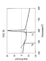
- a Nasicon type LAGP having a relatively higher ion conductivity among the phosphate compounds was vitrified, and the resultant solid electrolyte material had low transition temperatures, Tg (glass transition point) of approximately 480°C and Tx (crystallization temperature) of approximately 590°C (see FIG. 10 ).
- This glass material had a firing shrinkage initiation temperature of 550°C to 600°C.
- the inventors found a condition for preventing the deterioration in the charge-discharge ability of the electrode active material due to the reaction between the electrode active material and the solid electrolyte material while maintaining sufficient connection of the solid electrolyte particles.
- the above problems were solved based on this finding.
- the particle boundary resistance between the solid electrolyte particles could be lowered while preventing the reduction in the capacity of the electrode active material, and the electrolyte network could be formed in the electrode layer. Therefore, the connection interface area between the electrode active material and the solid electrolyte material could be remarkably increased to lower the interface reaction resistance, and thus the resultant all-solid-state cell was capable of charge and discharge operations even in the all solid state.
- an all-solid-state cell comprises positive and negative electrode portions containing an electrode active material, an electrolyte portion containing a solid electrolyte, and positive and negative collector portions, and is characterized in that the one or both of the positive and negative electrode portions are formed by mixing and firing the electrode active material and an amorphous solid electrolyte material, which satisfy the inequality: Ty > Tz wherein Ty is a temperature at which the capacity of the electrode active material is lowered by a reaction between the electrode active material and the solid electrolyte material, and Tz is a temperature at which the solid electrolyte material is shrunk by firing.
- Tz is a temperature at which the relative density of the solid electrolyte material is increased to 70% or more of the theoretical density thereof due to the firing shrinkage.
- Tz is preferably a temperature at which the relative density of the material is increased to 80% or more due to the firing shrinkage within the temperature range of Ty > Tz.
- Ty is a temperature at which the charge-discharge capacity of the electrode active material is lowered below 50% of the original theoretical capacity thereof.
- Ty is preferably a temperature at which the charge-discharge capacity of the electrode active material is 80% or more of the theoretical capacity within the temperature range of Ty > Tz.
- the solid electrolyte material may comprise an amorphous polyanion compound, and the one or both of the positive and negative electrode portions may be formed by mixing and firing the electrode active material and the solid electrolyte material.
- the solid electrolyte material may comprise an amorphous phosphate compound, and the one or both of the positive and negative electrode portions may be formed by mixing and firing the electrode active material and the solid electrolyte material.
- the solid electrolyte material comprising the phosphate compound may be of Nasicon type after the firing.
- the phosphate compound of the solid electrolyte material may be LAGP Li 1+x Al x Ge 2-x (PO 4 ) 3 or LATP Li 1+x Al x Ti 2-x (PO 4 ) 3 (0 ⁇ x ⁇ 1).
- the electrode active material may be a Nasicon type material comprising a phosphate compound.
- the phosphate compound of the electrode active material may be LVP Li m V 2 (PO 4 ) 3 (1 ⁇ m ⁇ 5).
- the electrode active material for the positive electrode portion may be an olivine type positive electrode active material comprising a phosphate compound.
- the phosphate compound of the positive electrode active material may be LNP Li n NiPO 4 , LCP Li n CoPO 4 , LMP Li n MnPO 4 or LFP Li n FePO 4 (0 ⁇ n ⁇ 1).
- the solid electrolyte material and the electrode active material may be of Nasicon type after the firing.
- the all-solid-state cell may have such a symmetrical structure that the solid electrolyte material and the electrode active material are of Nasicon type, the solid electrolyte material comprises LAGP Li 1+x Al x Ge 2-x (PO 4 ) 3 (0 ⁇ x ⁇ 1, preferably 0.3 ⁇ x ⁇ 0.7), and the electrode active material comprises LVP Li m V 2 (PO 4 ) 3 (1 ⁇ m ⁇ 5) in both the positive and negative electrode portions.
- the one or both of the positive and negative electrode portions may be formed by firing under an applied pressure.
- a dense microstructure can be formed in the one or both of the positive and negative electrode portion, the interface area between the electrode active material and the solid electrolyte material can be increased, and the interface charge transfer resistance can be lowered.
- one or both of the positive and negative electrode portions may be formed from a paste for printing by firing it under an inert atmosphere.
- a binder component can be carbonized to ensure the electron conductivity of the electrode portion.
- the electron conductivity of the electrode portion can be maintained without intentional addition of a carbon component useful as an electron conducting aid.
- the particle boundary resistance between the solid electrolyte particles can be lowered while preventing the reduction in the capacity of the electrode active material in the electrode layer.
- the electrolyte network can be formed in the electrode layer, the connection interface area between the electrode active material and the solid electrolyte material can be remarkably increased, the interface reaction resistance can be lowered, and thus the resultant all-solid-state cell is capable of charge and discharge operations even in the all solid state.
- an all-solid-state cell 10 comprises a combination of an electrode active material and a solid electrolyte material.
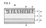
- the all-solid-state cell 10 has a fired solid electrolyte plate 14 of a ceramic containing a solid electrolyte 12, a first electrode layer 18 (e.g. a positive electrode) integrally formed on one surface of the fired solid electrolyte plate 14 by mixing and firing an electrode active material 16 and a solid electrolyte 12, a second electrode layer 20 (e.g.
- a negative electrode integrally formed on the other surface of the fired solid electrolyte plate 14 by mixing and firing an electrode active material 16 and a solid electrolyte 12, a first collector electrode 24 electrically connected to the first electrode layer 18, and a second collector electrode 26 electrically connected to the second electrode layer 20.
- the fired solid electrolyte plate 14 substantially acts as a solid electrolyte portion separating the positive and negative electrodes.
- the solid electrolyte 12 contained in the ceramic of the fired solid electrolyte plate 14 is not particularly limited, and may be selected from known conventional solid electrolytes.
- the solid electrolyte 12 preferably contains a lithium ion as a movable ion, and examples thereof include lithium ion-conductive solid glass electrolytes such as Li 3 PO 4 , LiPON (Li 3 PO 4 mixed with nitrogen), Li 2 S-SiS 2 , Li 2 S-P 2 S 5 , and Li 2 S-B 2 S 3 , and lithium ion-conductive solid electrolytes prepared by doping the glass with a lithium halide (e.g. LiI) or a lithium oxoate (e.g.
- a lithium halide e.g. LiI
- a lithium oxoate e.g.
- the solid electrolyte 12 is particularly preferably a titanium oxide type solid electrolyte containing lithium, titanium, and oxygen, such as Li x La y TiO 3 (0 ⁇ x ⁇ 1, 0 ⁇ y ⁇ 1), or a Nasicon type phosphate compound such as Li 1+x Al x Ge 2-x (PO 4 ) 3 or Li 1+x Al x Ti 2-x (PO 4 ) 3 (0 ⁇ x ⁇ 1), which can exhibit a stable performance even in the case of firing under an oxygen atmosphere.
- a titanium oxide type solid electrolyte containing lithium, titanium, and oxygen such as Li x La y TiO 3 (0 ⁇ x ⁇ 1, 0 ⁇ y ⁇ 1), or a Nasicon type phosphate compound such as Li 1+x Al x Ge 2-x (PO 4 ) 3 or Li 1+x Al x Ti 2-x (PO 4 ) 3 (0 ⁇ x ⁇ 1), which can exhibit a stable performance even in the case of firing under an oxygen atmosphere.
- the thickness of the fired solid electrolyte plate 14 is not particularly limited, and is preferably 5 ⁇ m to 1 mm, more preferably 5 ⁇ m to 100 ⁇ m.
- a large number of powder particles of the solid electrolyte 12 are bonded by sintering to form a porous body.
- a porous body a plurality of pores are three-dimensionally connected from the surface to the inside, and are filled with the electrode active material 16.
- the thicknesses of the first electrode layer 18 and the second electrode layer 20 are not particularly limited, and are preferably 5 ⁇ m to 1 mm, more preferably 5 ⁇ m to 500 ⁇ m.
- a first paste for forming the first electrode layer 18 and a second paste for forming the second electrode layer 20 may be printed into electrode patterns on the fired solid electrolyte plate 14 respectively using a screen printing method, etc.
- the first and second pastes may be produced by the steps of dissolving a binder in an organic solvent to prepare a solution, adding an appropriate amount of the solution to powders of the electrode active material and the solid electrolyte material to be hereinafter described, and kneading the resultant mixture.
- the electrode patterns of the first and second pastes printed on the fired solid electrolyte plate 14 may be fired at a temperature lower than a temperature for forming the fired solid electrolyte plate 14, to form the first electrode layer 18 and the second electrode layer 20.
- the obtained first electrode layer 18 and second electrode layer 20 are the porous bodies having a large number of pores filled with the electrode active material 16.
- both the first electrode layer 18 and the second electrode layer 20 formed on the fired solid electrolyte plate 14 are composed of a ceramic containing a mixture of the electrode active material 16 and the solid electrolyte 12 in the above example
- the second electrode layer 20 may be composed of a metal film 22 of a Li metal or Li alloy, like an all-solid-state cell 10a according to another example shown in FIG. 2 .
- the solid electrolyte material added to the first electrode layer 18 and the second electrode layer 20 may comprise an amorphous polyanion compound, and the layers may be formed by firing the compound.
- the solid electrolyte material added to the first electrode layer 18 and the second electrode layer 20 may comprise an amorphous phosphate compound, and the layers may be formed by firing the compound.
- the solid electrolyte material comprising the phosphate compound may be of Nasicon type after the firing, and the phosphate compound is particularly preferably LAGP Li 1+x Al x Ge 2-x (PO 4 ) 3 or LATP Li 1+x Al x Ti 2-x (PO 4 ) 3 (0 ⁇ x ⁇ 1).
- the electrode active material may be a Nasicon type material comprising a phosphate compound, and the phosphate compound is particularly preferably LVP Li m V 2 (PO 4 ) 3 (1 ⁇ m ⁇ 5).
- the positive electrode active material may be an olivine type material comprising a phosphate compound, and the phosphate compound is particularly preferably LNP Li n NiPO 4 , LCP Li n CoPO 4 , LMP Li n MnPO 4 or LFP Li n FePO 4 (0 ⁇ n ⁇ 1).
- the solid electrolyte material and the electrode active material comprising the phosphate compounds may be of Nasicon type after the firing.
- the solid electrolyte material comprises LAGP Li 1+x Al x Ge 2-x (PO 4 ) 3 (0 ⁇ x ⁇ 1, preferably 0.3 ⁇ x ⁇ 0.7), and both the positive and negative electrode active materials comprise LVP Li m V 2 (PO 4 ) 3 (1 ⁇ m ⁇ 5), whereby the all-solid-state cell has a symmetrical structure.
- the particle boundary resistance between the solid electrolyte particles can be lowered while preventing formation of a heterophase due to a reaction between the solid electrolyte material and the electrode active material 16.
- the electrolyte network can be formed in the first electrode layer 18 and the second electrode layer 20, whereby the connection interface area between the electrode active material 16 and the solid electrolyte 12 can be remarkably increased to lower the interface reaction resistance, and thus the resultant all-solid-state cell 10 is capable of charge and discharge operations even in the all solid state.
- the first electrode layer 18 and the second electrode layer 20 are preferably formed by firing under an applied pressure.
- a dense microstructure can be formed in the electrode portion, the interface area between the electrode active material and the solid electrolyte material can be increased, and the interface charge transfer resistance can be lowered.
- the methods for firing the layers under an applied pressure include a Hot Isostatic Pressing HIP, in which a mixture is heated at a high temperature while pressure is simultaneously and isotropically applied to the mixture, and a Hot Pressing, in which a mixture housed in a firing jig is heat-treated as a whole while pressure is uniaxially applied to the mixture.
- a gas such as argon can be used as a pressure medium to apply isotropic pressure to the mixture.
- the first electrode layer 18 and/or the second electrode layer 20 may be formed from a paste for printing by firing it under an inert atmosphere such as an Ar atmosphere.
- a binder component can be carbonized to ensure the electron conductivity of the first electrode layer 18 and/or the second electrode layer 20.
- the electron conductivity of the first electrode layer 18 and/or the second electrode layer 20 can be maintained without intentional addition of a carbon component useful as an electron conducting aid.
- LAGP Li 1.5 Al 0.5 Ge 1.5 (PO 4 ) 3
- LAGP crystal powder was press-formed using a mold into a compact powder pellet having a diameter of 16 mm and a thickness of approximately 1 mm.
- the pressure for the forming was 500 kg/cm 2 .
- the pellet was fired at 840°C in the air to obtain a fired solid electrolyte pellet of LAGP.
- the LAGP crystal powder obtained by the solid-phase method was put in a Pt crucible and placed in a furnace under an air atmosphere heated at 1200°C for 1 hour. Then, the LAGP crystal powder was taken out and rapidly cooled by iced water, to obtain a vitrified LAGP.
- the vitrified LAGP was pulverized using a mortar, a ball mill, etc. to prepare a fine LAGP glass powder.
- a solid electrolyte pellet of the LAGP crystal powder (hereinafter referred to as the crystalline LAGP solid electrolyte) and a solid electrolyte pellet of the LAGP glass powder (hereinafter referred to as the vitrified LAGP solid electrolyte) were produced, and the sintered states of the pellets were compared at different firing temperatures under an Ar atmosphere.
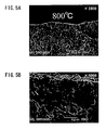
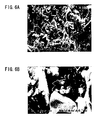
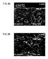
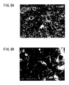
- the results of SEM observation of fracture cross sections in the pellets are shown in FIGS. 3A and 3B to 9A and 9B , and shrinkage properties of the pellets due to the firing under the Ar atmosphere are shown in the graphs of FIGS. 11 and 12 .
- FIGS. 3A and 3B to 5A and 5B include SEM photographs showing cross sections of the crystalline LAGP solid electrolyte fired at 600°C, 700°C, and 800°C.
- Each of FIGS. 3A , 4A and 5A is an SEM photograph at x 1000 magnification
- each of FIGS. 3B , 4B and 5B is an SEM photograph at x 5000 magnification.
- FIGS. 6A and 6B to 9A and 9B include SEM photographs showing cross sections of the vitrified LAGP solid electrolyte fired at 550°C, 600°C, 650°C, and 700°C.
- FIGS. 6A , 7A , 8A and 9A is an SEM photograph at x 1000 magnification
- each of FIGS. 6B , 7B , 8B and 9B is an SEM photograph at x 5000 magnification.
- FIG. 10 is a graph showing a DTA (differential thermal analysis) property of the vitrified LAGP solid electrolyte in an inert atmosphere (N 2 atmosphere). It is clear from FIG. 10 that the vitrified LAGP solid electrolyte had low transition temperatures, Tg (glass transition point) of approximately 480°C and Tx (crystallization temperature) of approximately 590°C.
- Tg glass transition point
- Tx crystalstallization temperature
- FIG. 11 is a characteristic diagram showing changes of the firing shrinkage (%) and the internal impedance of the crystalline LAGP solid electrolyte depending on the firing temperature.
- FIG. 12 is a characteristic diagram showing changes of the firing shrinkage (%) and the internal impedance of the vitrified LAGP solid electrolyte depending on the firing temperature.
- the firing shrinkage of each LAGP solid electrolyte is shown by plotted black dots, and the internal impedance is divided into two corresponding to the intraparticle resistance and the particle boundary resistance and shown by bar graph.
- An electron conducting aid of acetylene black was added to a mixture of the LAGP crystal powder and the LVP crystal powder to carry out an evaluation using an electrolytic solution later.
- a powder pellet of the mixture was prepared and fired at a firing temperature under an Ar atmosphere to obtain a fired body.
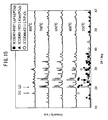
- the obtained fired body was subjected to an XRD (X-ray diffraction) measurement.
- the measurement results are shown in FIG. 13 .
- peaks of Li 3 Fe 2 (PO 4 ) 3 for identifying the crystal structure of the LVP are marked with black squares
- peaks of LiGe 2 (PO 4 ) 3 for identifying the crystal structure of the LAGP are marked with black triangles.
- the LAGP and the LVP are not registered in ICDD, and thus the compounds having the same crystal structures were used for the identification. As shown in the measurement results, a plurality of peaks of a heterophase derived from a condensed phosphate salt were observed in addition to the peaks of the LAGP and LVP at temperatures of 700°C and 800°C, at which the LAGP crystal powder was sintered.
- FIG. 14 the change of the charge-discharge capacity of the positive electrode active material is shown by plotted black squares.
- the peak intensities of the main peak (a) of the positive electrode active material and the main peak (b) of the heterophase are shown in the bar graph.
- the reduction in the peak intensity of the positive electrode active material and the generation of the heterophase derived from vanadium contained in the positive electrode active material corresponded to the reduction in the charge-discharge capacity of the positive electrode active material.
- the capacity reduction due to the reaction between the solid electrolyte material and the electrode active material in the high-temperature firing caused the reduction in the charge-discharge ability of the electrode active material.
- the electrode active material was converted to LiVP 2 O 7 , which was identified beforehand. Further, the electrode active material exhibited a charge-discharge capacity significantly lower than the original theoretical capacity at temperatures of 700°C and 800°C, at which the LAGP crystal powder was sintered.
- An electron conducting aid of acetylene black was added to a mixture of the LAGP glass powder and the LVP crystal powder to carry out an evaluation using an electrolytic solution later.
- a powder pellet of the mixture was prepared and fired at a firing temperature under an Ar atmosphere to obtain a fired body.
- the obtained fired body was subjected to an XRD (X-ray diffraction) measurement. Further, the fired body was used in a system containing the electrolytic solution, and the charge-discharge ability of the electrode active material was evaluated.
- the XRD measurement results are shown in FIG. 15
- the charge-discharge ability evaluation results are shown in FIG. 16 .
- the plotted marks in FIGS. 15 and 16 have the same meanings as those in FIGS. 13 and 14 .
- the particles of the LAGP glass powder were suitably bonded to each other around 600°C.
- the electrode active material maintained a sufficient peak intensity and had a charge-discharge capacity close to the original theoretical capacity thereof without formation of a heterophase.
- the combination of the materials containing the phosphate compounds using a common polyanion was considered as a material system satisfying the relation that the temperature, at which the capacity of the electrode active material is lowered by the reaction between the electrode active material and the solid electrolyte material, is higher than the firing shrinkage initiation temperature of the solid electrolyte material.
- All-solid-state cells having electrodes containing the combinations of the electrode active materials and the solid electrolyte materials were produced respectively.
- the electrode was formed by mixing and firing the electrode active material and the solid electrolyte material of an amorphous LAGP solid electrolyte (an amorphous polyanion (phosphate) compound) in Examples.
- a crystalline LAGP solid electrolyte was used instead of the amorphous LAGP solid electrolyte in Comparative Examples. Examples and Comparative Examples will be described specifically below.
- a binder was dissolved in an organic solvent, and an appropriate amount of the resultant solution was added to the LAGP glass powder and the LVP crystal powder.
- the mixture was kneaded in a mortar to prepare an electrode paste for screen printing.
- the obtained electrode paste was printed into an electrode pattern having a diameter of 12 mm on each surface of a fired solid electrolyte body (a base) having a diameter of 13 mm and a thickness of 1 mm.
- the printed electrode patterns were dried to form positive and negative electrodes.
- the electrodes were bonded to the surfaces of the solid electrolyte base by firing at 600°C for 2 hours using a firing furnace under an Ar atmosphere. Then, a sputtered gold (Au) film having a thickness of approximately 50 nm was formed as a collector on each surface of the resultant fired body.
- Au sputtered gold
- the positive electrode After the firing, the positive electrode had a thickness of approximately 20 ⁇ m and an active material content of approximately 2 mg.
- the charge-discharge capacity per unit weight of the positive electrode was calculated from the active material content, and was shown in a graph.
- a binder was dissolved in an organic solvent, and an appropriate amount of the resultant solution was added to the LAGP glass powder and the LVP crystal powder.
- the mixture was kneaded in a mortar to prepare an electrode paste for screen printing.
- the obtained electrode paste was printed into an electrode pattern and dried on each surface of a fired solid electrolyte body (a base) in the above-mentioned manner, to form positive and negative electrodes.
- the electrodes were bonded to the surfaces of the solid electrolyte base by firing at 600°C for 40 hours using a firing furnace under an Ar atmosphere. Then, a sputtered Au film was formed on each surface of the resultant fired body.
- the positive electrode After the firing, the positive electrode had a thickness of approximately 20 ⁇ m and an active material content of approximately 2 mg as above.
- a binder was dissolved in an organic solvent, and an appropriate amount of the resultant solution was added to the LAGP crystal powder and the LVP crystal powder.
- the mixture was kneaded in a mortar to prepare an electrode paste for screen printing.
- the obtained electrode paste was printed into an electrode pattern and dried on each surface of a fired solid electrolyte body (a base) in the above-mentioned manner, to form positive and negative electrodes.
- the electrodes were bonded to the surfaces of the solid electrolyte base by firing at 600°C for 2 hours using a firing furnace under an Ar atmosphere. Then, a sputtered Au film was formed on each surface of the resultant fired body.
- the positive electrode After the firing, the positive electrode had a thickness of approximately 20 ⁇ m and an active material content of approximately 2 mg as above.
- a binder was dissolved in an organic solvent, and an appropriate amount of the resultant solution was added to the LAGP crystal powder and the LVP crystal powder.
- the mixture was kneaded in a mortar to prepare an electrode paste for screen printing.
- the obtained electrode paste was printed into an electrode pattern and dried on each surface of a fired solid electrolyte body (a base) in the above-mentioned manner, to form positive and negative electrodes.
- the electrodes were bonded to the surfaces of the solid electrolyte base by firing at 700°C for 2 hours using a firing furnace under an Ar atmosphere. Then, a sputtered Au film was formed on each surface of the resultant fired body.
- the positive electrode After the firing, the positive electrode had a thickness of approximately 20 ⁇ m and an active material content of approximately 2 mg as above.
- the alternating-current impedance of each all-solid-state cell was measured by using 1287 Potentiostat/Galvanostat (trade name) and 1255B Frequency Response Analyzer (trade name) manufactured by Solartron in combination.
- the measurement frequency was controlled within the range of 1 MHz to 0.1 Hz, and the measurement signal voltage was 10 mV.
- Each all-solid-state cell was charged and discharged by a CCCV (Constant Current Constant Voltage) process, and the charge-discharge property was evaluated. Specifically, in Examples 1 and 2, the all-solid-state cell was charged at a constant current of 9 ⁇ A/cm 2 to a cutoff voltage of 2.4 V and then charged at a constant voltage of 2.4 V to a current value of 0.9 ⁇ A/cm 2 , and was discharged at a constant current of 9 ⁇ A/cm 2 to a cutoff voltage of 0.1 V and then discharged at a constant voltage of 0.1 V to a current value of 0.9 ⁇ A/cm 2 .
- CCCV Constant Current Constant Voltage
- the all-solid-state cell was charged at a constant current of 0.9 ⁇ A/cm 2 to a cutoff voltage of 2.4 V and then charged at a constant voltage of 2.4 V to a current value of 0.45 ⁇ A/cm 2 , and was discharged at a constant current of 0.9 ⁇ A/cm 2 to a cutoff voltage of 0.1 V and then discharged at a constant voltage of 0.1 V to a current value of 0.45 ⁇ A/cm 2 .
- Each of the produced all-solid-state ceramic cells having the mixture electrodes was vacuum-dried under heating and incorporated in a 2032 coin cell type package to evaluate the electric properties in a glove box.
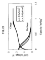
- the charge-discharge properties of Examples 1 and 2 and Comparative Examples 1 and 2 are shown in FIGS. 17 , 19 , 21 , and 23 .
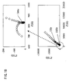
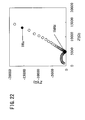
- the alternating-current impedances of Examples 1 and 2 and Comparative Examples 1 and 2 are shown in FIGS. 18 , 20 , 22 , and 24 .
- the transverse axis indicates the real part Z' of the impedance
- the ordinate axis indicates the imaginary part Z'' of the impedance
- the measurement frequencies of 1 kHz and 1 Hz are marked with black dots.
- Comparative Example 1 a large arc corresponding to the particle boundary resistance was formed in a higher frequency region of more than 1 kHz in the alternating-current impedance waveform, and the solid electrolyte particles were not sufficiently bonded to each other. Thus, the reaction interface area between the solid electrolyte material and the electrode active material was insufficient, whereby the cell of Comparative Example 1 was almost incapable of charge and discharge.
- Comparative Example 2 a large arc corresponding to the reaction interface resistance was formed in a lower frequency region of 1 kHz or less in the alternating-current impedance waveform. Thus, a heterophase was formed on the connection interface between the solid electrolyte material and the electrode active material, and the capacity of the electrode active material was lowered, whereby the cell of Comparative Example 2 was almost incapable of charge and discharge.
- Example 1 had a low internal resistance and a charge-discharge capacity of approximately 20 mAh/g, and the cell of Example 2 had a charge-discharge capacity of approximately 40 mAh/g.
- each cell had low impedance in terms of both the particle boundary resistance and the interface reaction resistance as shown in the alternating-current impedance waveform, since the solid electrolyte particles were sufficiently bonded in a region of the electrode layer where a defect (formation of a heterophase, reduction in the capacity of the active material, etc.) was not generated between the solid electrolyte material and the electrode active material.
- the solid electrolyte material and the electrode active material had an increased desirable connection interface, whereby the interface reaction resistance was lowered.
- the internal resistance was lowered, so that the resultant cell was capable of charge and discharge.
- Example 3 An all-solid-state cell of Example 3 was produced, and the charge/discharge property and the alternating-current impedance property were measured.
- Example 2 In the same manner as Example 1, a binder was dissolved in an organic solvent, and an appropriate amount of the resultant solution was added to the LAGP glass powder and the LVP crystal powder. The mixture was kneaded in a mortar to prepare an electrode paste for screen printing. The obtained electrode paste was printed into an electrode pattern having a diameter of 12 mm on each surface of a fired solid electrolyte body (a base) having a diameter of 13 mm and a thickness of 1 mm. The printed electrode patterns were dried to form positive and negative electrodes.
- the electrodes were bonded to the surfaces of the solid electrolyte base by firing while applying a load of 500 kg/cm 2 in the thickness direction at 600°C for 40 hours using a hot-press furnace under an Ar atmosphere. Then, a sputtered gold (Au) film having a thickness of approximately 50 nm was formed as a collector on each surface of the resultant fired body.
- Au sputtered gold
- the positive electrode had a thickness of approximately 20 ⁇ m and an active material content of approximately 2 mg as Example 1.
- the alternating-current impedance of the all-solid-state cell was measured by using 1287 Potentiostat/Galvanostat (trade name) and 1255B Frequency Response Analyzer (trade name) manufactured by Solartron in combination in the same manner as Example 1.
- the measurement frequency was controlled within the range of 1 MHz to 0.1 Hz, and the measurement signal voltage was 10 mV.
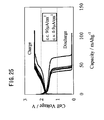
- the produced all-solid-state cell was charged and discharged by a CCCV process, and the charge-discharge property was evaluated. Specifically, in Examples 3, the all-solid-state cell was charged at a constant current of 90 ⁇ A/cm 2 to a cutoff voltage of 2.4 V and then charged at a constant voltage of 2.4 V to a current value of 0.9 ⁇ A/cm 2 , and was discharged at a constant current of 90 ⁇ A/cm 2 to a cutoff voltage of 0.1 V and then discharged at a constant voltage of 0.1 V to a current value of 0.9 ⁇ A/cm 2 .
- the produced all-solid-state ceramic cell having the mixture electrodes was vacuum-dried under heating and incorporated in a 2032 coin cell type package to evaluate the electric properties in a glove box.
- the charge-discharge property of Example 3 is shown in FIG. 25
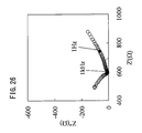
- the alternating-current impedance of Example 3 is shown in FIG. 26 .
- the transverse axis indicates the real part Z' of the impedance
- the ordinate axis indicates the imaginary part Z'' of the impedance
- the measurement frequencies of 1 kHz and 1 Hz are marked with black dots.
- Example 3 as is clear from FIG. 26 , the internal resistance was lowered.
- the reduction in the reaction resistance (the interface charge transfer resistance) accounts for the majority of the reduction in the internal resistance, and thus the reduction may be achieved due to densification and increase of the connection interface area between the electrode active material and the solid electrolyte material.
Landscapes
- Chemical & Material Sciences (AREA)
- Chemical Kinetics & Catalysis (AREA)
- Electrochemistry (AREA)
- General Chemical & Material Sciences (AREA)
- Inorganic Chemistry (AREA)
- Engineering & Computer Science (AREA)
- Manufacturing & Machinery (AREA)
- Physics & Mathematics (AREA)
- Condensed Matter Physics & Semiconductors (AREA)
- General Physics & Mathematics (AREA)
- Crystallography & Structural Chemistry (AREA)
- Secondary Cells (AREA)
Applications Claiming Priority (2)
| Application Number | Priority Date | Filing Date | Title |
|---|---|---|---|
| JP2007293682 | 2007-11-12 | ||
| JP2008268333A JP5304168B2 (ja) | 2007-11-12 | 2008-10-17 | 全固体電池 |
Publications (2)
| Publication Number | Publication Date |
|---|---|
| EP2058880A1 true EP2058880A1 (de) | 2009-05-13 |
| EP2058880B1 EP2058880B1 (de) | 2017-10-25 |
Family
ID=40342231
Family Applications (1)
| Application Number | Title | Priority Date | Filing Date |
|---|---|---|---|
| EP08253682.2A Ceased EP2058880B1 (de) | 2007-11-12 | 2008-11-11 | Festkörperzelle |
Country Status (2)
| Country | Link |
|---|---|
| US (2) | US20090123847A1 (de) |
| EP (1) | EP2058880B1 (de) |
Cited By (2)
| Publication number | Priority date | Publication date | Assignee | Title |
|---|---|---|---|---|
| EP2096693B1 (de) * | 2008-02-22 | 2017-04-26 | Kyushu University | All-Solid-State-Zelle |
| CN109560248A (zh) * | 2018-11-13 | 2019-04-02 | 中兴高能技术有限责任公司 | 复合正极材料、叠层单元及制备方法和全固态锂离子电池 |
Families Citing this family (29)
| Publication number | Priority date | Publication date | Assignee | Title |
|---|---|---|---|---|
| US9166230B1 (en) | 2007-01-12 | 2015-10-20 | Enovix Corporation | Three-dimensional battery having current-reducing devices corresponding to electrodes |
| WO2008089110A1 (en) | 2007-01-12 | 2008-07-24 | Microazure Corporation | Three-dimensional batteries and methods of manufacturing the same |
| JP5551542B2 (ja) * | 2009-09-17 | 2014-07-16 | 株式会社オハラ | 全固体電池および全固体電池の製造方法 |
| JP2011096630A (ja) * | 2009-10-02 | 2011-05-12 | Sanyo Electric Co Ltd | 固体リチウム二次電池及びその製造方法 |
| FR2956523B1 (fr) * | 2010-02-18 | 2012-04-27 | Centre Nat Rech Scient | Procede de preparation d'une batterie monolithique par frittage sous courant pulse |
| US9843027B1 (en) | 2010-09-14 | 2017-12-12 | Enovix Corporation | Battery cell having package anode plate in contact with a plurality of dies |
| US20130183589A1 (en) * | 2010-09-28 | 2013-07-18 | Toyota Jidosha Kabushiki Kaisha | Battery sintered body, producing method of battery sintered body and all solid lithium battery |
| CN103636054B (zh) * | 2011-07-08 | 2016-03-02 | 株式会社村田制作所 | 全固体电池及其制造方法 |
| US10283811B2 (en) | 2011-09-30 | 2019-05-07 | Corning Incorporated | Micromachined electrolyte sheet |
| US8841030B2 (en) * | 2012-01-24 | 2014-09-23 | Enovix Corporation | Microstructured electrode structures |
| EP2807698B1 (de) | 2012-01-24 | 2018-01-10 | Enovix Corporation | Ionisch durchlässige strukturen für energiespeichereinrichtungen |
| KR20240055130A (ko) | 2012-08-16 | 2024-04-26 | 에노빅스 코오퍼레이션 | 3차원 배터리들을 위한 전극 구조들 |
| US20170040643A1 (en) * | 2012-10-25 | 2017-02-09 | Centre National De La Recherche Scientifique | Method for preparing a solid-state battery by sintering under pulsating current |
| KR102038624B1 (ko) | 2012-12-21 | 2019-10-31 | 삼성전자주식회사 | 보호 음극, 이를 포함하는 리튬 공기 전지, 및 리튬 이온 전도성 보호막의 제조방법 |
| CN105308772B (zh) | 2013-03-15 | 2018-11-16 | 艾诺维克斯公司 | 用于三维电池的隔膜 |
| JP6524775B2 (ja) * | 2014-05-19 | 2019-06-05 | Tdk株式会社 | リチウムイオン二次電池 |
| JP6455807B2 (ja) | 2014-05-19 | 2019-01-23 | Tdk株式会社 | リチウムイオン二次電池 |
| JP2016035913A (ja) | 2014-07-31 | 2016-03-17 | 富士フイルム株式会社 | 全固体二次電池、ならびに、無機固体電解質粒子、固体電解質組成物、電池用電極シートおよび全固体二次電池の製造方法 |
| JP6222142B2 (ja) | 2015-03-05 | 2017-11-01 | トヨタ自動車株式会社 | 電極体の製造方法 |
| TWI793480B (zh) | 2015-05-14 | 2023-02-21 | 美商易諾維公司 | 用於能量儲存裝置之縱向約束 |
| JP6354716B2 (ja) | 2015-09-08 | 2018-07-11 | トヨタ自動車株式会社 | 硫化物固体電池 |
| TWI739830B (zh) | 2016-05-13 | 2021-09-21 | 美商易諾維公司 | 用於三維電池之尺寸拘束件 |
| US11233289B2 (en) * | 2016-08-01 | 2022-01-25 | Cps Technology Holdings Llc | Weldable aluminum terminal pads of an electrochemical cell |
| TWI819481B (zh) | 2016-11-16 | 2023-10-21 | 美商易諾維公司 | 具有可壓縮陰極之三維電池 |
| US10256507B1 (en) | 2017-11-15 | 2019-04-09 | Enovix Corporation | Constrained electrode assembly |
| KR102859540B1 (ko) | 2017-11-15 | 2025-09-17 | 에노빅스 코오퍼레이션 | 전극 어셈블리 및 2차 배터리 |
| US11211639B2 (en) | 2018-08-06 | 2021-12-28 | Enovix Corporation | Electrode assembly manufacture and device |
| JP7844451B2 (ja) | 2020-09-18 | 2026-04-13 | エノビクス・コーポレイション | 電池に使用する電極の製造 |
| CN116783744A (zh) | 2020-12-09 | 2023-09-19 | 艾诺维克斯公司 | 用于制造二次电池的电极组合件的方法及装置 |
Citations (8)
| Publication number | Priority date | Publication date | Assignee | Title |
|---|---|---|---|---|
| JP2000311710A (ja) | 1999-04-27 | 2000-11-07 | Kyocera Corp | 固体電解質電池およびその製造方法 |
| US6355379B1 (en) * | 1999-02-03 | 2002-03-12 | Sanyo Electric Co., Ltd. | Polymer electrolyte batteries having improved electrode/electrolyte interface |
| JP2005063958A (ja) | 2003-07-29 | 2005-03-10 | Mamoru Baba | 薄膜固体リチウムイオン二次電池およびその製造方法 |
| US20060078790A1 (en) * | 2004-10-05 | 2006-04-13 | Polyplus Battery Company | Solid electrolytes based on lithium hafnium phosphate for active metal anode protection |
| WO2007075867A2 (en) * | 2005-12-19 | 2007-07-05 | Polyplus Battery Company | Composite solid electrolyte for protection of active metal anodes |
| US20070175020A1 (en) * | 2006-01-27 | 2007-08-02 | Matsushita Electric Industrial Co., Ltd. | Method for producing solid state battery |
| EP1826861A1 (de) * | 2006-02-24 | 2007-08-29 | Ngk Insulators, Ltd. | Feststoffbatterie |
| US20070259271A1 (en) * | 2004-12-13 | 2007-11-08 | Tetsuo Nanno | Laminate Including Active Material Layer and Solid Electrolyte Layer, and All Solid Lithium Secondary Battery Using the Same |
Family Cites Families (13)
| Publication number | Priority date | Publication date | Assignee | Title |
|---|---|---|---|---|
| JP3198828B2 (ja) * | 1994-11-01 | 2001-08-13 | 松下電器産業株式会社 | 全固体リチウム二次電池の製造法 |
| JP2000251938A (ja) | 1999-02-25 | 2000-09-14 | Kyocera Corp | 全固体リチウム電池の製造方法 |
| JP2000331684A (ja) | 1999-05-24 | 2000-11-30 | Kyocera Corp | 積層型固体二次電池 |
| JP2001210360A (ja) | 2000-01-26 | 2001-08-03 | Kyocera Corp | 全固体二次電池の製造方法 |
| KR100590376B1 (ko) * | 2003-03-20 | 2006-06-19 | 마쯔시다덴기산교 가부시키가이샤 | 집합전지 |
| TW200638568A (en) * | 2004-12-02 | 2006-11-01 | Ohara Kk | All solid lithium ion secondary battery and a solid electrolyte therefor |
| JP2007134305A (ja) | 2005-10-13 | 2007-05-31 | Ohara Inc | リチウムイオン伝導性固体電解質およびその製造方法 |
| US9580320B2 (en) * | 2005-10-13 | 2017-02-28 | Ohara Inc. | Lithium ion conductive solid electrolyte and method for manufacturing the same |
| JP5115920B2 (ja) | 2006-02-24 | 2013-01-09 | 日本碍子株式会社 | 全固体電池 |
| US7914932B2 (en) * | 2006-02-24 | 2011-03-29 | Ngk Insulators, Ltd. | All-solid-state battery |
| US20070231704A1 (en) * | 2006-03-30 | 2007-10-04 | Ohara Inc. | Lithium ion conductive solid electrolyte and production process thereof |
| JP2007294429A (ja) | 2006-03-30 | 2007-11-08 | Ohara Inc | リチウムイオン伝導性固体電解質およびその製造方法 |
| JP5110565B2 (ja) * | 2007-03-08 | 2012-12-26 | トヨタ自動車株式会社 | リチウム二次電池、正極活物質被覆用粒子の製造方法およびリチウム二次電池の製造方法 |
-
2008
- 2008-11-10 US US12/267,659 patent/US20090123847A1/en not_active Abandoned
- 2008-11-11 EP EP08253682.2A patent/EP2058880B1/de not_active Ceased
-
2014
- 2014-03-24 US US14/223,169 patent/US9209484B2/en active Active
Patent Citations (9)
| Publication number | Priority date | Publication date | Assignee | Title |
|---|---|---|---|---|
| US6355379B1 (en) * | 1999-02-03 | 2002-03-12 | Sanyo Electric Co., Ltd. | Polymer electrolyte batteries having improved electrode/electrolyte interface |
| JP2000311710A (ja) | 1999-04-27 | 2000-11-07 | Kyocera Corp | 固体電解質電池およびその製造方法 |
| JP2005063958A (ja) | 2003-07-29 | 2005-03-10 | Mamoru Baba | 薄膜固体リチウムイオン二次電池およびその製造方法 |
| US20060078790A1 (en) * | 2004-10-05 | 2006-04-13 | Polyplus Battery Company | Solid electrolytes based on lithium hafnium phosphate for active metal anode protection |
| US20070259271A1 (en) * | 2004-12-13 | 2007-11-08 | Tetsuo Nanno | Laminate Including Active Material Layer and Solid Electrolyte Layer, and All Solid Lithium Secondary Battery Using the Same |
| WO2007075867A2 (en) * | 2005-12-19 | 2007-07-05 | Polyplus Battery Company | Composite solid electrolyte for protection of active metal anodes |
| US20070172739A1 (en) * | 2005-12-19 | 2007-07-26 | Polyplus Battery Company | Composite solid electrolyte for protection of active metal anodes |
| US20070175020A1 (en) * | 2006-01-27 | 2007-08-02 | Matsushita Electric Industrial Co., Ltd. | Method for producing solid state battery |
| EP1826861A1 (de) * | 2006-02-24 | 2007-08-29 | Ngk Insulators, Ltd. | Feststoffbatterie |
Non-Patent Citations (1)
| Title |
|---|
| YUSUKE FUKUSHIMA: "Fabrication of electrode-electrolyte interface in all-solid-state cell lithium batteries using the thermal softening adhesion behavior of Li2S-P2S5 glass electrolytes", LECTURE SUMMARY OF CHEMICAL BATTERY MATERIAL ASSOCIATION MEETING, vol. 9TH, 11 June 2007 (2007-06-11), pages 51 - 52 |
Cited By (2)
| Publication number | Priority date | Publication date | Assignee | Title |
|---|---|---|---|---|
| EP2096693B1 (de) * | 2008-02-22 | 2017-04-26 | Kyushu University | All-Solid-State-Zelle |
| CN109560248A (zh) * | 2018-11-13 | 2019-04-02 | 中兴高能技术有限责任公司 | 复合正极材料、叠层单元及制备方法和全固态锂离子电池 |
Also Published As
| Publication number | Publication date |
|---|---|
| US9209484B2 (en) | 2015-12-08 |
| EP2058880B1 (de) | 2017-10-25 |
| US20090123847A1 (en) | 2009-05-14 |
| US20140205891A1 (en) | 2014-07-24 |
Similar Documents
| Publication | Publication Date | Title |
|---|---|---|
| US9209484B2 (en) | All-solid-state cell | |
| EP2096693B1 (de) | All-Solid-State-Zelle | |
| US9209486B2 (en) | All-solid-state cell | |
| JP5299860B2 (ja) | 全固体電池 | |
| JP5304168B2 (ja) | 全固体電池 | |
| US12438183B2 (en) | Solid electrolyte sheet, method for manufacturing same, and sodium ion all-solid-state secondary cell | |
| KR102410194B1 (ko) | 나트륨 이온 전지용 전극합재, 그 제조 방법 및 나트륨 전고체 전지 | |
| JP7273513B2 (ja) | 固体Li-S電池およびその作製方法 | |
| KR101862665B1 (ko) | 펄스 전류 소결 방식에 의한 고체 상태의 배터리 제조 방법 | |
| CN111699582B (zh) | 全固体电池 | |
| WO2019239890A1 (ja) | 非晶質固体電解質およびそれを用いた全固体二次電池 | |
| US20170040643A1 (en) | Method for preparing a solid-state battery by sintering under pulsating current | |
| EP3671931A1 (de) | Festelektrolytschicht und feststoffbatterie | |
| JPWO2011111555A1 (ja) | 全固体二次電池およびその製造方法 | |
| JP2011192606A (ja) | 電解質・電極積層体の製造方法、電解質・電極積層体及び全固体電池 | |
| WO2021054245A1 (ja) | 二次電池用電極及びその製造方法 | |
| JP2018116776A (ja) | 全固体電池および全固体電池の製造方法 | |
| CN120202573A (zh) | 固态电池及其制造方法 | |
| US12119443B2 (en) | Solid-state electrolyte, solid-state battery including the electrolyte, and method of making the same | |
| EP4459637A1 (de) | Festelektrolytfolie und verfahren zur herstellung davon | |
| KR20250053603A (ko) | 전고체 전지 | |
| CN119365429A (zh) | 锂离子电导性玻璃材料 | |
| KR100393636B1 (ko) | 박막리튬 이차전지의 전해질 조성물 및 제조방법 |
Legal Events
| Date | Code | Title | Description |
|---|---|---|---|
| PUAI | Public reference made under article 153(3) epc to a published international application that has entered the european phase |
Free format text: ORIGINAL CODE: 0009012 |
|
| 17P | Request for examination filed |
Effective date: 20081128 |
|
| AK | Designated contracting states |
Kind code of ref document: A1 Designated state(s): AT BE BG CH CY CZ DE DK EE ES FI FR GB GR HR HU IE IS IT LI LT LU LV MC MT NL NO PL PT RO SE SI SK TR |
|
| AX | Request for extension of the european patent |
Extension state: AL BA MK RS |
|
| RIN1 | Information on inventor provided before grant (corrected) |
Inventor name: YOSHIDA, TOSHIHIRO Inventor name: OKADA, SHIGETO Inventor name: YAMAMOTO, KAZUHIRO Inventor name: KOBAYASHI, EIJI Inventor name: SATO, YOSUKE |
|
| 17Q | First examination report despatched |
Effective date: 20090728 |
|
| RIN1 | Information on inventor provided before grant (corrected) |
Inventor name: SATO, YOSUKE Inventor name: YOSHIDA, TOSHIHIRO Inventor name: YAMAMOTO, KAZUHIRO Inventor name: KOBAYASHI, EIJIC/O INST.FOR MATERIALS CHEMISTRY AN Inventor name: OKADA, SHIGETOC/O INST.FOR MATERIALS CHEMISTRY AND |
|
| AKX | Designation fees paid |
Designated state(s): DE FR GB |
|
| STAA | Information on the status of an ep patent application or granted ep patent |
Free format text: STATUS: EXAMINATION IS IN PROGRESS |
|
| REG | Reference to a national code |
Ref country code: DE Ref legal event code: R079 Ref document number: 602008052625 Country of ref document: DE Free format text: PREVIOUS MAIN CLASS: H01M0004580000 Ipc: H01M0010056200 |
|
| GRAP | Despatch of communication of intention to grant a patent |
Free format text: ORIGINAL CODE: EPIDOSNIGR1 |
|
| STAA | Information on the status of an ep patent application or granted ep patent |
Free format text: STATUS: GRANT OF PATENT IS INTENDED |
|
| RIC1 | Information provided on ipc code assigned before grant |
Ipc: H01M 10/0562 20100101AFI20170328BHEP Ipc: H01M 4/58 20100101ALI20170328BHEP |
|
| INTG | Intention to grant announced |
Effective date: 20170502 |
|
| RAP1 | Party data changed (applicant data changed or rights of an application transferred) |
Owner name: KYUSHU UNIVERSITY Owner name: NGK INSULATORS, LTD. |
|
| RAP1 | Party data changed (applicant data changed or rights of an application transferred) |
Owner name: KYUSHU UNIVERSITY Owner name: NGK INSULATORS, LTD. |
|
| GRAS | Grant fee paid |
Free format text: ORIGINAL CODE: EPIDOSNIGR3 |
|
| GRAJ | Information related to disapproval of communication of intention to grant by the applicant or resumption of examination proceedings by the epo deleted |
Free format text: ORIGINAL CODE: EPIDOSDIGR1 |
|
| GRAL | Information related to payment of fee for publishing/printing deleted |
Free format text: ORIGINAL CODE: EPIDOSDIGR3 |
|
| STAA | Information on the status of an ep patent application or granted ep patent |
Free format text: STATUS: EXAMINATION IS IN PROGRESS |
|
| GRAR | Information related to intention to grant a patent recorded |
Free format text: ORIGINAL CODE: EPIDOSNIGR71 |
|
| STAA | Information on the status of an ep patent application or granted ep patent |
Free format text: STATUS: GRANT OF PATENT IS INTENDED |
|
| RAP1 | Party data changed (applicant data changed or rights of an application transferred) |
Owner name: KYUSHU UNIVERSITY Owner name: NGK INSULATORS, LTD. |
|
| RIN1 | Information on inventor provided before grant (corrected) |
Inventor name: YOSHIDA, TOSHIHIRO Inventor name: YAMAMOTO, KAZUHIRO Inventor name: OKADA, SHIGETO Inventor name: KOBAYASHI, EIJI Inventor name: SATO, YOSUKE |
|
| GRAA | (expected) grant |
Free format text: ORIGINAL CODE: 0009210 |
|
| STAA | Information on the status of an ep patent application or granted ep patent |
Free format text: STATUS: THE PATENT HAS BEEN GRANTED |
|
| INTC | Intention to grant announced (deleted) | ||
| INTG | Intention to grant announced |
Effective date: 20170914 |
|
| AK | Designated contracting states |
Kind code of ref document: B1 Designated state(s): DE FR GB |
|
| REG | Reference to a national code |
Ref country code: GB Ref legal event code: FG4D |
|
| REG | Reference to a national code |
Ref country code: FR Ref legal event code: PLFP Year of fee payment: 10 |
|
| REG | Reference to a national code |
Ref country code: DE Ref legal event code: R096 Ref document number: 602008052625 Country of ref document: DE |
|
| REG | Reference to a national code |
Ref country code: DE Ref legal event code: R097 Ref document number: 602008052625 Country of ref document: DE |
|
| PLBE | No opposition filed within time limit |
Free format text: ORIGINAL CODE: 0009261 |
|
| STAA | Information on the status of an ep patent application or granted ep patent |
Free format text: STATUS: NO OPPOSITION FILED WITHIN TIME LIMIT |
|
| 26N | No opposition filed |
Effective date: 20180726 |
|
| REG | Reference to a national code |
Ref country code: FR Ref legal event code: PLFP Year of fee payment: 11 |
|
| PGFP | Annual fee paid to national office [announced via postgrant information from national office to epo] |
Ref country code: DE Payment date: 20181030 Year of fee payment: 11 |
|
| PGFP | Annual fee paid to national office [announced via postgrant information from national office to epo] |
Ref country code: GB Payment date: 20181107 Year of fee payment: 11 Ref country code: FR Payment date: 20181011 Year of fee payment: 11 |
|
| REG | Reference to a national code |
Ref country code: DE Ref legal event code: R119 Ref document number: 602008052625 Country of ref document: DE |
|
| GBPC | Gb: european patent ceased through non-payment of renewal fee |
Effective date: 20191111 |
|
| PG25 | Lapsed in a contracting state [announced via postgrant information from national office to epo] |
Ref country code: GB Free format text: LAPSE BECAUSE OF NON-PAYMENT OF DUE FEES Effective date: 20191111 Ref country code: DE Free format text: LAPSE BECAUSE OF NON-PAYMENT OF DUE FEES Effective date: 20200603 Ref country code: FR Free format text: LAPSE BECAUSE OF NON-PAYMENT OF DUE FEES Effective date: 20191130 |