EP2059111A1 - Dispositif d'alimentation de bande et appareil de montage - Google Patents
Dispositif d'alimentation de bande et appareil de montage Download PDFInfo
- Publication number
- EP2059111A1 EP2059111A1 EP07792924A EP07792924A EP2059111A1 EP 2059111 A1 EP2059111 A1 EP 2059111A1 EP 07792924 A EP07792924 A EP 07792924A EP 07792924 A EP07792924 A EP 07792924A EP 2059111 A1 EP2059111 A1 EP 2059111A1
- Authority
- EP
- European Patent Office
- Prior art keywords
- tape
- component
- mounting apparatus
- pickup position
- feeding action
- Prior art date
- Legal status (The legal status is an assumption and is not a legal conclusion. Google has not performed a legal analysis and makes no representation as to the accuracy of the status listed.)
- Granted
Links
Images






Classifications
-
- H—ELECTRICITY
- H05—ELECTRIC TECHNIQUES NOT OTHERWISE PROVIDED FOR
- H05K—PRINTED CIRCUITS; CASINGS OR CONSTRUCTIONAL DETAILS OF ELECTRIC APPARATUS; MANUFACTURE OF ASSEMBLAGES OF ELECTRICAL COMPONENTS
- H05K13/00—Apparatus or processes specially adapted for manufacturing or adjusting assemblages of electric components
- H05K13/04—Mounting of components, e.g. of leadless components
- H05K13/0417—Feeding with belts or tapes
-
- H—ELECTRICITY
- H05—ELECTRIC TECHNIQUES NOT OTHERWISE PROVIDED FOR
- H05K—PRINTED CIRCUITS; CASINGS OR CONSTRUCTIONAL DETAILS OF ELECTRIC APPARATUS; MANUFACTURE OF ASSEMBLAGES OF ELECTRICAL COMPONENTS
- H05K13/00—Apparatus or processes specially adapted for manufacturing or adjusting assemblages of electric components
- H05K13/04—Mounting of components, e.g. of leadless components
- H05K13/0417—Feeding with belts or tapes
- H05K13/0419—Feeding with belts or tapes tape feeders
-
- Y—GENERAL TAGGING OF NEW TECHNOLOGICAL DEVELOPMENTS; GENERAL TAGGING OF CROSS-SECTIONAL TECHNOLOGIES SPANNING OVER SEVERAL SECTIONS OF THE IPC; TECHNICAL SUBJECTS COVERED BY FORMER USPC CROSS-REFERENCE ART COLLECTIONS [XRACs] AND DIGESTS
- Y10—TECHNICAL SUBJECTS COVERED BY FORMER USPC
- Y10T—TECHNICAL SUBJECTS COVERED BY FORMER US CLASSIFICATION
- Y10T29/00—Metal working
- Y10T29/49—Method of mechanical manufacture
- Y10T29/49002—Electrical device making
- Y10T29/49117—Conductor or circuit manufacturing
- Y10T29/49124—On flat or curved insulated base, e.g., printed circuit, etc.
- Y10T29/4913—Assembling to base an electrical component, e.g., capacitor, etc.
- Y10T29/49133—Assembling to base an electrical component, e.g., capacitor, etc. with component orienting
-
- Y—GENERAL TAGGING OF NEW TECHNOLOGICAL DEVELOPMENTS; GENERAL TAGGING OF CROSS-SECTIONAL TECHNOLOGIES SPANNING OVER SEVERAL SECTIONS OF THE IPC; TECHNICAL SUBJECTS COVERED BY FORMER USPC CROSS-REFERENCE ART COLLECTIONS [XRACs] AND DIGESTS
- Y10—TECHNICAL SUBJECTS COVERED BY FORMER USPC
- Y10T—TECHNICAL SUBJECTS COVERED BY FORMER US CLASSIFICATION
- Y10T29/00—Metal working
- Y10T29/53—Means to assemble or disassemble
- Y10T29/5313—Means to assemble electrical device
- Y10T29/53174—Means to fasten electrical component to wiring board, base, or substrate
-
- Y—GENERAL TAGGING OF NEW TECHNOLOGICAL DEVELOPMENTS; GENERAL TAGGING OF CROSS-SECTIONAL TECHNOLOGIES SPANNING OVER SEVERAL SECTIONS OF THE IPC; TECHNICAL SUBJECTS COVERED BY FORMER USPC CROSS-REFERENCE ART COLLECTIONS [XRACs] AND DIGESTS
- Y10—TECHNICAL SUBJECTS COVERED BY FORMER USPC
- Y10T—TECHNICAL SUBJECTS COVERED BY FORMER US CLASSIFICATION
- Y10T29/00—Metal working
- Y10T29/53—Means to assemble or disassemble
- Y10T29/5313—Means to assemble electrical device
- Y10T29/53174—Means to fasten electrical component to wiring board, base, or substrate
- Y10T29/53178—Chip component
-
- Y—GENERAL TAGGING OF NEW TECHNOLOGICAL DEVELOPMENTS; GENERAL TAGGING OF CROSS-SECTIONAL TECHNOLOGIES SPANNING OVER SEVERAL SECTIONS OF THE IPC; TECHNICAL SUBJECTS COVERED BY FORMER USPC CROSS-REFERENCE ART COLLECTIONS [XRACs] AND DIGESTS
- Y10—TECHNICAL SUBJECTS COVERED BY FORMER USPC
- Y10T—TECHNICAL SUBJECTS COVERED BY FORMER US CLASSIFICATION
- Y10T29/00—Metal working
- Y10T29/53—Means to assemble or disassemble
- Y10T29/5313—Means to assemble electrical device
- Y10T29/53191—Means to apply vacuum directly to position or hold work part
Definitions
- the present invention relates to a tape feeder that is attached to a mounting apparatus and supplies electronic components, and a mounting apparatus.
- a tape feeder as a component supplying apparatus that is to be attached to a mounting apparatus for mounting electronic components on a board and supplies electronic components to the mounting apparatus.
- Such a tape feeder is configured, as described in the patent document 1 indicated below, in such a way that a tape that holds components disposed at fixed intervals is wound on a reel and the tape unwound from the attached reel is fed to a pickup position where a transfer head in the mounting apparatus sucks an electronic component.
- the tape that holds electronic components engages a sprocket provided in the tape feeder, and the sprocket intermittently rotates by a predetermined feeding amount. In this way, the electronic components held on the tape successively reach the pickup position.
- An object of the present invention is to provide a tape feeder and a mounting apparatus which can reduce waste of components.
- a tape feeder includes a sprocket that engages a tape that holds components at predetermined intervals, a motor that rotates the sprocket to feed the tape to a predetermined pickup position, and a controller that drives and controls the motor.
- the controller is configured to carry out a tape feeding action in which the motor is driven in the forward direction to successively feed the components held on the tape to the pickup position, and a reverse feeding action in which the motor is driven in the reverse direction to return a component fed to the pickup position to a position upstream of the pickup position in the tape feeding direction.
- the tape feeder can return a component that has been fed to the pickup position to a position upstream of the pickup position in the reverse feeding action, such a component can be reused, and hence the amount of waste of components can be reduced.
- the controller when the controller receives a removal instruction to remove the tape feeder from a mounting apparatus, the controller allows to carry out the reverse feeding action to return the component that has been fed to the pickup position or the position immediately upstream thereof in the tape feeding direction to a covered position where the component is not exposed to the outside.
- the component when the tape feeder is still attached to the mounting apparatus and a component has been fed to the pickup position or the position immediately upstream thereof, the component is returned in the reverse feeding action to a covered position where the component is not exposed to the outside when the tape feeder is removed from the mounting apparatus. It is thus possible to prevent in advance the component, for example, from dropping when the tape feeder is removed.
- a mounting apparatus is a mounting apparatus to which the tape feeder described above is attachable.
- the amount of return in the reverse feeding action is related to identification information and stored, the identification information allowing the tape feeder to be identified, whereas when the tape feeder is attached to the mounting apparatus, the tape feeder is instructed to carry out the tape feeding action based on the amount of return that has been related to the identification information on the tape feeder and stored.
- the mounting apparatus when the tape feeder that has been removed from the mounting apparatus is reattached to the mounting apparatus, the tape feeding action is carried out based on the amount of return at the time of the removal. It is thus possible to quickly start manufacturing boards using the reattached tape feeder.
- a mounting apparatus is a mounting apparatus to which the tape feeder described above is attachable, and includes a photographing device for photographing the vicinity of the pickup position for the tape feeder.
- the mounting apparatus is configured, when the tape feeder is attached to the mounting apparatus, to instruct the photographing device to photograph the vicinity of the pickup position for the tape feeder and the tape feeder to carry out the tape feeding action in such a way that in the captured image, the first component reaches the pickup position or the position immediately upstream thereof in the tape feeding direction.
- the tape feeding action is carried out in such a way that in the captured image showing the vicinity of the pickup position, the first component reaches the pickup position or the position immediately upstream thereof. It is thus possible to quickly start manufacturing boards using the attached tape feeder.
- the mounting apparatus is a mounting apparatus to which a plurality of tape feeders are attachable, each of the tape feeders successively feeding components held on a component supplying tape at predetermined intervals to a predetermined pickup position.
- the mounting apparatus includes a transfer head that picks up and transfers a component fed to the pickup position for each of the tape feeders to a predetermined mounting position on a board, and a tape feeding action controller for controlling each of the tape feeders so as to feed components held on the tape to the pickup position and carry out a tape feeding action to place the component that has not been picked up in the pickup position again, when the transfer head has not picked up a component.
- the mounting apparatus for example, when the transfer head fails to pick up a component, the component that has been unsuccessfully picked up is placed in the pickup position again. Therefore, the component that has been fed to the pickup position but, for example, has been unsuccessfully sucked is not discarded but can be reused to reduce waste of components.
- FIG 1 is a plan view showing a mounting apparatus according to a first embodiment of the present invention (a mounting apparatus to which a tape feeder according to the present invention is attached).
- the mounting apparatus 10 includes conveyers 20, 20 that are disposed on a base 11 and transport printed boards P, component suppliers 30 disposed on both sides of the conveyers 20, 20, and an electronic component mounting head unit 40 provided above the base 11.
- the head unit 40 can move across an area between any of the component suppliers 30 and a mounting position on a board P so that the head unit 40 can pick up an electronic component from the component supplier 30 and mount the electronic component in a predetermined mounting position on the board P.
- the head unit 40 is movably supported in an X-axis direction (the direction in which the conveyers 20 transport boards) by a head unit supporting member 42 extending in the X-axis direction, and both ends of the head unit supporting member 42 are in turn movably supported in a Y-axis direction (the direction perpendicular to the X-axis direction in a horizontal plane) by guide rails 43, 43 extending in the Y-axis direction.
- the head unit 40 is driven by an X-axis motor 44 via a ball screw shaft 45 in the X-axis direction, and the head unit supporting member 42 is driven by a Y-axis motor 46 via a ball screw shaft 47 in the Y-axis direction.
- a plurality of transfer heads 41 arranged in the X-axis direction are mounted on the head unit 40.
- Each of the transfer heads 41 is driven in the up-down direction (Z-axis direction) by a lifting mechanism using a Z-axis motor as a driving source, and also driven in the rotational direction (R-axis direction) by a rotary drive mechanism using an R-axis motor as a driving source.
- a suction nozzle for sucking an electronic component and mount it on a board is provided at the tip of each of the transfer heads 41.
- a negative pressure is supplied from a negative pressure device (not shown) to each of the nozzles when a component is sucked, and a suction force resulting from the negative pressure can be used to suck and pick up an electronic component.
- a pressure sensor (not shown) that detects the level of the negative pressure is also provided in each of the nozzles. The pressure sensor can judge from the change in the negative pressure in each of the nozzles whether or not the nozzle has successfully picked up (sucked) a component.
- a board photographing camera 48 comprised of a CCD camera or any other similar camera equipped with an illuminator is also provided in the head unit 40.
- the board photographing camera 48 can photograph a position reference mark and a board ID mark provided on a board P that has been transported in the mounting apparatus 10.
- the board photographing camera 48 also serves as photographing device for photographing the vicinity of an electronic component pickup position for each of tape feeders 50 attached to the component suppliers 30.
- the number of component suppliers 30 is four in total, upstream and downstream component suppliers provided on the front side of the conveyers 20, 20, and upstream and downstream component suppliers provided on the rear side.
- a plurality of tape feeders 50 as component supplying devices can be arranged and attached onto a feeder plate 31 of each of the component suppliers 30.
- Component photographing cameras 12, 12 are provided on the front and rear sides between the upstream component supplier 30 and the downstream component supplier 30. Each of the component photographing cameras 12, 12 photographs a component sucked by the head unit 40 to detect, for example, whether the component is misaligned with the suction nozzle. Each of the component photographing cameras 12, 12 can also judge from the presence or absence of a component sucked by any of the suction nozzles whether or not the suction nozzle has successfully picked up (sucked) the component. The component photographing camera 12 therefore serves, along with the pressure sensor provided in each of the suction nozzles, as a component pickup success/failure judgment device.
- Figure 2 is a diagram for explaining a schematic configuration of a tape feeder according to an embodiment of the present invention.
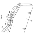
- Figure 3 is a perspective view of a front portion of the tape feeder.
- Figure 4 is a plan view showing an example of a component supplying tape installed in the tape feeder.
- the tape feeder 50 is configured as a motorized component supplying device including a motor 51 as a driving source.
- a reel 61 around which a tape 60 that holds electronic components is wound is attached to the tape feeder 50.
- the tape 60 unwound from the reel 61 is fed by a sprocket 52 rotated by the motor 51.
- the tape 60 has component pockets 62 that store and hold ICs, transistors, or other small-sized components 64 at predetermined intervals.
- the tape 60 also has perforations 63 right next to a center of the component pockets 62 at the same intervals as the component pockets 62 in a feeding direction.
- the interval (pitch) between components 64 on the tape 60 is hereinafter referred to as one frame.
- a cover tape 60a is provided over the upper side of the tape 60 so that openings of the component pockets 62 are covered.
- Radially protruding pins 54 are provided on the sprocket 52 in the tape feeder 50 at the same intervals as the perforations 63 in the tape.
- the pins 54 provided on the sprocket 52 engage the perforations 63 provided in the tape 60 to feed the tape 60.
- the electronic components 64 held on the tape 60 are successively fed to a predetermined pickup position 53 where the head unit 40 picks up the electronic components.
- a tape guide member 56 that guides the running tape 60 is provided over a front portion of the tape feeder 50, and the pickup position 53 is set within an exposing hole 56b provided in the tape guide member 56.
- a cover tape outlet hole 56a that separates the cover tape 60a from a tape body 60b and removes the cover tape 60a is provided upstream of the exposing hole 56b in the tape running direction.
- the portion between the cover tape outlet hole 56a and the exposing hole 56b within which the pickup position 53 is set serves as a tape cover 57 that covers the space above component pockets 62 from which the cover tape 60a is separated, and prevents the components 64 in these component pockets 62 from being exposed to the outside.
- the portion that the tape cover 57 or the portion of the tape guide member 56 that is upstream of the cover tape outlet hole 56a prevents from being exposed to the outside is hereinafter referred to as a covered position.
- the motor 51 that rotates the sprocket 52 can rotate both in forward and backward directions, and is comprised of a servo motor or any other similar motor that can control the angle of rotation (phase).
- the rotation of the motor 51 is controlled in accordance with a control signal from a controller 55 provided in the tape feeder 50.
- the controller 55 drives the motor 51 in the forward direction to carry out a tape feeding action in which the components 64 held on the tape 60 are successively fed to the pickup position 53.
- the controller 55 can also reverse the motor 51 as required to carry out a reverse feeding action in which components 64 that have been fed to the pickup position 53 or positions downstream thereof are returned to positions upstream of the pickup position 53.
- the reverse feeding action will be described later.
- the controller 55 in the tape feeder 50 is electrically connected to a controller 15 in the mounting apparatus 10 so that the mounting apparatus 10 supplies electric power for driving the motor 51 and other components and a control signal for driving the motor 51 and other signals are communicated between the tape feeder 50 and the mounting apparatus 10.
- the controller 15 in the mounting apparatus 10 and the controller 55 in the tape feeder 50 cooperate to control actions in the mounting apparatus 10 in which the tape feeder 50 is incorporated. These controllers serve as a tape feeding action controller for instructing the tape feeder 50 to carry out the tape feeding action and the reverse feeding action at each timing in a component mounting action, which will be described later.
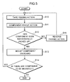
- Figure 5 is a flowchart showing the procedure of the component mounting action in the mounting apparatus according to the present embodiment.
- Figure 6 explains a case where a component has been unsuccessfully picked up in the mounting action.
- the tape feeding action is first carried out (step S10), and then a component pickup action is carried out (step S11) in which any of the suction nozzles sucks and picks up a component 64 that has been fed to the pickup position 53.
- step S12 It is then judged whether the component has been successfully picked up (step S12).
- whether or not the pickup action has been successfully carried out is judged from the nozzle's negative pressure value detected by the pressure sensor that serves as the pickup success/failure judgment device and the suction nozzle's vertical position data in the lifting mechanism that drives the transfer head 41, that is, the suction nozzle in the Z-axis direction.
- the judgment is made, after the negative pressure increases when the suction nozzle in the pickup position 53 is lowered to the suction position and the tip of the suction nozzle abuts a component, by judging whether or not the elevated negative pressure decreases after the suction nozzle in the pickup position 53 is lifted by a predetermined amount.
- the pickup action has been successfully carried out when the elevated negative pressure is maintained after the suction nozzle in the pickup position 53 is lifted by a predetermined amount.
- the head unit 40 then moves the suction nozzle to the area above the component photographing cameras 12, 12, it is judged from a photographing result obtained by using the component photographing cameras 12, 12 to photograph the component sucked by the suction nozzle whether or not the component has dropped from the suction nozzle during the horizontal motion.
- step S12 When the component has been successfully picked up (YES in the step S12), the component picked up by the suction nozzle is mounted on a board (step S13). When there are still components to be mounted on the board, the above actions are repeated (YES in the step S14), whereas there is no component to be mounted, the procedure is terminated (NO in the step S14).
- step S12 when the component pickup action has failed (NO in the step S12), the component X that should have been picked up is left in the pickup position 53, as shown in Figure 6A .
- the reverse feeding action step S15 is carried out to return the component X to the position immediately upstream of the pickup position 53 by one frame (by the interval between components 64 on the tape 60) in the tape feeding direction. The control then returns to the action step for mounting the next component.
- step S10 allows the component X that has been unsuccessfully picked up to be resupplied to the pickup position 53 and reused in the following pickup action, as shown in Figure 6C . It is thus possible to prevent the component that has been unsuccessfully picked up from being wasted.
- Figure 7 is a flowchart showing a procedure of actions carried out when no component is picked up but only the tape feeding action is carried out in the mounting apparatus according to the present embodiment.
- Figure 8 explains the above actions.
- checking whether components are fed, for example, in a stable manner is carried out when a forced tape feeding input that forces the tape feeding action to be carried out is made by an operator or any other person to an input switch provided in the tape feeder 50, an input operation unit in the mounting apparatus 10, or any other input-related unit (step S20).
- the tape feeder 50 When the forced tape feeding input is made (YES in the step S20), the tape feeder 50 carries out the tape feeding action, but no component 64 is picked up in the pickup position 53 (step S21). In this process, the operator or any other person visually inspects or otherwise checks the tape feeding action. At the same time, the controller 55 in the tape feeder 50 counts and stores the amount of tape feed (the number of frames) in the tape feeding action carried out in response to the forced tape feeding input (step S22).
- the checking whether components are fed for example, in a stable manner is carried out by repeating the tape feeding action described above multiple times.
- components 64 are left in an area downstream of the pickup position 53, The number of components 64 being the number of tape feeding actions (the number of frames) repeated without the pickup action.
- step S23 After the operator or any other person has carried out the tape feeding action arbitrary times, the operation of the mounting apparatus 10 is resumed when a tape return input that returns the tape is made by the operator or any other person to an input switch provided in the tape feeder 50, an input operation unit in the mounting apparatus 10, or any other input-related unit (step S23).
- step S23 When the tape returning input is made (YES in the step S23), the tape is reversed by a plurality of frames (step S24) based on the amount of feed (the number of frames) obtained by counting the tape feeding action carried out in response to the forced tape feeding input, and the operation is allowed to resume (step S25).
- the tape returning input may not be necessarily made by the operator or any other person.
- the control proceeds to the step S20, whereas when the lapsed time exceeds the predetermined period, a monitor (not shown) displays a message indicating that there is no tape returning input and the operation is allowed to resume (step S25).
- the first component X is fed to the pickup position 53 and used. Therefore, even when the tape feeding action is carried out but no pickup action is carried out to check whether components are fed, for example, in a stable manner, components fed to an area downstream of the pickup position 53 will not be discarded or wasted, but can be effectively used.
- Figure 9A is a flowchart showing a procedure of actions carried out when any of the tape feeders is removed from the mounting apparatus according to the present embodiment.
- Figure 9B is a flowchart showing a procedure of actions carried out when the tape feeder is attached to the mounting apparatus.
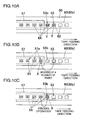
- Figure 10 explains the above actions.
- step S30 removal of any of the tape feeders 50 from the mounting apparatus 10 is initiated by a feeder removal instruction issued from the controller 15 in the mounting apparatus 10 or a removal instruction inputted by the operator or any other person (step S30).
- the input from the operator or any other person is made to an input switch provided in the tape feeder 50, an input operation unit in the mounting apparatus 10, or any other input-related unit, and transferred to the controller 55 in the tape feeder 50.
- the controller in the tape feeder 50 that has received the feeder removal instruction reversed the tape by multiple frames to return the component that has been fed to the pickup position to any of the covered positions where the component is not exposed to the outside (step S31), and stores the number of reversed frames (step S32).
- the operation of storing the number of reversed frames may be carried out either by the controller 55 in the tape feeder 50 or the controller 15 in the mounting apparatus 10.
- the controller 15 in the mounting apparatus 10 stores the number
- the number is related to a feeder number or other identification information that allows the tape feeder in question to be identified before the number is stored.
- the first component X has been fed to the pickup position 53.
- the tape is reversed by multiple frames until the first component X reaches a covered position 57a where the tape cover 57 hides the first component X.
- the amount of return in the reverse feeding action may be set to a predetermined number of frames or may be set based on the information on the position of the first component when the tape feeder 50 is removed.
- the reverse feeding action may be carried out to return the first component X to an upstream position beyond the most downstream position.
- the tape may be reversed by multiple frames until the component Y in the position immediately upstream of the pickup position 53 is returned to any of the covered positions 57a.
- the controller 55 in the tape feeder 50 notifies the operator or any other person via a display section provided in the tape feeder 50, a monitor screen provided in the mounting apparatus 10, or any other display section that the tape feeder 50 is allowed to be removed (step S33). In response to the notification, the operator or any other person removes the tape feeder 50 from the mounting apparatus 10 (step S34).
- the reverse feeding action is carried out when any of the tape feeders 50 is removed from the mounting apparatus 10. Therefore, when the corresponding tape feeder 50 is still attached to the mounting apparatus, and there is a component 64 fed to the pickup position 53 or the position immediately upstream thereof, the component 64 is returned to any of the covered positions 57a where the component 64 is not exposed to the outside. It is thus possible to prevent in advance such a component from dropping when the tape feeder 50 is removed.
- attaching the tape feeder 50 to the mounting apparatus 10 is initiated by the operator or any other person's action of actually attaching the tape feeder 50 to the mounting apparatus 10 (step S40).
- the controller 55 in the tape feeder 50 or the controller 15 in the mounting apparatus 10 judges whether or not the controller stores the amount of return (the number of reversed frames) made when the tape feeder 50 was removed (step S42).
- the controller 15 in the mounting apparatus 10 makes the judgment, the identification information of the attached tape feeder 50 is read, and it is judged whether or not there is a stored amount of return related to the identification information.
- step S42 When the amount of return (the number of reversed frames) is stored (YES in the step S42), the tape feeding action is carried out in accordance with the stored number of reversed frames (step S43), and the operation of the mounting apparatus 10 is allowed to resume (step S44).
- the reverse feeding action from Figure 10A to Figure 10B causes the first component X in the pickup position 53 to be returned by 2 frames.
- Figure 10C considering that the component feeding action is carried out before the component pickup operation, the tape is fed by one frame, the number obtained by subtracting one frame from the amount of return, which is 2 frames, in order to feed the first component X back to the position 53b immediately upstream of the pickup position 53.
- the tape When no component feeding action is carried out before the component pickup action, the tape may be fed by 2 frames, which is the amount of return, so that the first component X reaches the pickup position 53.
- the tape feeding action may be carried out by the number of frames that correspond to the amount of return.
- step S44 when the tape feeder 50 in question has not stored the number of reversed frames (NO in the step S42), the operation is, in principle, allowed to resume under the current condition of the mounting apparatus (step S44). In this case, no component may have reached the pickup position 53 or the position 53b immediately upstream thereof, but components will be ready to be supplied by carrying out the forced tape feeding action until the first component is fed to the pickup position 53 or the position 53b immediately upstream thereof.
- a state in which the first component is expected to be fed to the pickup position 53 or the position 53b immediately upstream thereof may be achieved by automatically carrying out the tape feeding action by a predetermined number of frames.
- the tape feeding action is carried out based on the amount of return at the time of the removal. It-is thus possible to quickly start manufacturing boards using the reattached tape feeder 50.
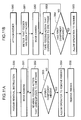
- Figure 11A is a flowchart showing another example of the procedure of actions of removing any of the tape feeders from the mounting apparatus according to the present embodiment
- Figure 11B is a flowchart showing another example of the procedure of actions of attaching the tape feeder to the mounting apparatus.
- the removal of any of the tape feeders 50 from the mounting apparatus 10 is initiated by a removal instruction issued from the controller 15 in the mounting apparatus 10 or the operator or any other person (step S50).
- the feeder removal instruction is transferred to the controller 15 in the mounting apparatus 10, and the controller 15 in the mounting apparatus 10 moves the board photographing camera 48, which serves as photographing device attached to the head unit 40, to a position where the board photographing camera 48 photographs the vicinity of the pickup position 53 for the tape feeder 50 to be removed (step S51).
- the tape feeder 50 While the vicinity of the pickup position 53 for the tape feeder 50 is being photographed, the tape feeder 50 is instructed to carry out the reverse feeding action frame by frame (step S52) until in the captured image, the first component in the pickup position 53, in the position 53b immediately upstream thereof, or in any other position reaches any of the covered positions 57a (No in the step S53) where the tape cover 57 hides the first component.
- the controller 15 in the mounting apparatus 10 notifies the operator or any other person via a display section provided in the tape feeder 50, a monitor screen provided in the mounting apparatus 10, or any other display section that the tape feeder 50 is allowed to be removed (step S54). In response to the notification, the operator or any other person removes the tape feeder 50 from the mounting apparatus 10 (step S55).
- the first component can thus be reliably returned to any of the covered positions when the tape feeder 50 is removed from the mounting apparatus 10, whereby it is possible to prevent in advance the component from dropping when the tape feeder 50 is removed.
- attaching the tape feeder 50 to the mounting apparatus 10 is initiated by the operator or the any other person's action of actually attaching the tape feeder 50 to the mounting apparatus 10 (step S60).
- the controller 15 in the mounting apparatus 10 moves the board photographing camera 48, which serves as photographing device attached to the head unit 40, to a position where the board photographing camera 48 photographs the vicinity of the pickup position 53 for the attached tape feeder 50 (step S62).
- the tape feeder 50 While the vicinity of the pickup position 53 for the tape feeder 50 is being photographed, the tape feeder 50 is instructed to carry out the tape feeding action frame by frame (step S63) until in the captured image, the first component appears and reaches the pickup position 53 or the position 53b immediately upstream thereof (No in the step S64).
- the controller 15 in the mounting apparatus 10 allows the operation using the tape feeder 50 to resume (step S65).
- the tape feeding action is carried out in such a way that the first component reaches the pickup position 53 or the position 53b immediately upstream thereof. It is thus possible to quickly start manufacturing boards using the attached tape feeder 50.
- the first component can be reliably fed to the pickup position 53 or the position 53b immediately upstream thereof.
- the configuration of the mounting apparatus according to the second embodiment is basically the same as that of the mounting apparatus according to the first embodiment (see Figures 1 to 4 ), but differs from the configuration of the mounting apparatus according to the first embodiment in that each of the tape feeders 50 is instructed to carry out only the tape feeding action in which components 64 held on the tape 60 are successively fed to the pickup position 53, but not to carry out the reverse feeding action in which components 64 are returned to an area upstream of the pickup position.
- the controller 15 in the mounting apparatus 10 and the controller 55 in each of the tape feeders 50 serve as a tape feeding action controller for instructing the tape feeder 50 to carry out the tape feeding action at each timing in the component mounting action.
- Figure 12 is a flowchart showing the procedure of the component mounting action in the mounting apparatus according to the second embodiment.
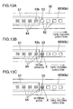
- Figure 13 explains a case where a component has been unsuccessfully picked up in the mounting action.
- the first component 64 is in the position 53b immediately upstream of the pickup position 53.
- the tape feeding action is first carried out (step S70) to feed the first component 64 to the pickup position 53, as shown in Figure 13B .
- the component pickup action in which any of the suction nozzles of the transfer head 41 sucks and picks up the component 64 fed to the pickup position 53 is then carried out (step S71).
- step S72 It is then judged whether the component has been successfully picked up (step S72).
- the component picked up by the suction nozzle is mounted on a board (step S73).
- the above actions are repeated (YES in the step S74), whereas there is no component to be mounted, the procedure is terminated (NO in the step S74).
- the mounting apparatus 10 does not carry out the tape feeding action (step S75), but the component pickup action is carried out again for the component X (step S71), as shown in Figure 13C .
- a tape feeder of the present invention includes a sprocket that engages a tape that holds components at predetermined intervals, a motor that rotates the sprocket to feed the tape to a predetermined pickup position, and a controller that drives and controls the motor.
- the controller is configured to carry out a tape feeding action in which the motor is driven in the forward direction to successively feed the components held on the tape to the pickup position, and a reverse feeding action in which the motor is driven in the reverse direction to return a component fed to the pickup position to a position upstream of the pickup position in the tape feeding direction.
- the tape feeder can return a component that has been fed to the pickup position to a position upstream of the pickup position in the reverse feeding action, such a component can be reused, and hence the amount of waste of components can be reduced.
- the tape can preferably be returned by a plurality of frames, where one frame corresponds to the interval between components held on the tape.
- the plurality of components that have been fed to positions downstream of the pickup position can be returned to positions upstream of the pickup position. It is thus possible to prevent the components from being wasted.
- the controller when the controller receives a removal instruction to remove the tape feeder from a mounting apparatus, the controller preferably carries out the reverse feeding action to return the component that has been fed to the pickup position or the position immediately upstream thereof in the tape feeding direction to a covered position where the component is not exposed to the outside.
- the component when the tape feeder is still attached to the mounting apparatus and a component has been fed to the pickup position or the position immediately upstream thereof, the component is returned in the reverse feeding action to a covered position where the component is not exposed to the outside when the tape feeder is removed from the mounting apparatus. It is thus possible to prevent in advance the component, for example, from dropping when the tape feeder is removed.
- the controller may be configured to store the amount of return in the reverse feeding action carried out in response to the removal instruction and carry out the tape feeding action based on the stored amount of return when the tape feeder is attached to the mounting apparatus later.
- the tape feeding action is carried out based on the amount of return at the time of the removal. It is thus possible to quickly start manufacturing boards using the reattached tape feeder.
- the tape feeder in which the controller carries out the reverse feeding action in response to the removal instruction issued from the mounting apparatus may further include photographing device for photographing the vicinity of the pickup position.
- the controller carries out the reverse feeding action based on the image captured by the photographing device in such a way that the first component reaches the covered position.
- the first component when the tape feeder is removed from the mounting apparatus, the first component can be reliably returned to the covered position. It is thus possible to prevent in advance the component from dropping when the tape feeder is removed.
- a mounting apparatus is a mounting apparatus to which, among the tape feeders described above, the tape feeder configured to carry out the reverse feeding action when the tape feeder receives a removal instruction from the mounting apparatus can be attached.
- the amount of return in the reverse feeding action is related to identification information and stored, the identification information allowing the tape feeder to be identified, whereas when the tape feeder is attached to the mounting apparatus, the tape feeder is instructed to carry out the tape feeding action based on the amount of return that has been related to the identification information on the tape feeder and stored.
- the mounting apparatus when the tape feeder that has been removed from the mounting apparatus is reattached to the mounting apparatus, the tape feeding action is carried out based on the amount of return at the time of the removal. It is thus possible to quickly start manufacturing boards using the reattached tape feeder.
- a mounting apparatus is a mounting apparatus to which, among the tape feeders described above, the tape feeder configured to carry out the reverse feeding action when the tape feeder receives a removal instruction from the mounting apparatus can be attached.
- the mounting apparatus includes photographing device for photographing the vicinity of the pickup position for the tape feeder.
- the mounting apparatus is configured, when the tape feeder is attached to the mounting apparatus, to instruct the photographing device to photograph the vicinity of the pickup position for the tape feeder and the tape feeder to carry out the tape feeding action in such a way that in the captured image, the first component reaches the pickup position or the position immediately upstream thereof in the tape feeding direction.
- the tape feeding action is carried out in such a way that in the captured image showing the vicinity of the pickup position, the first component reaches the pickup position or the position immediately upstream thereof. It is thus possible to quickly start manufacturing boards using the attached tape feeder.
- the mounting apparatus is a mounting apparatus to which a plurality of tape feeders can be attached, each of the tape feeders successively feeding components held on a component supplying tape at predetermined intervals to a predetermined pickup position.
- the mounting apparatus includes a transfer head that picks up and transfers a component fed to the pickup position for each of the tape feeders to a predetermined mounting position on a board, and a tape feeding action controller for controlling each of the tape feeders so as to feed components held on the tape to the pickup position and carry out a tape feeding action to place the component that has not been picked up in the pickup position again, when the transfer head has not picked up a component.
- the mounting apparatus for example, when the transfer head fails to pick up a component, the component is placed in the pickup position again. Therefore, the component that has been fed to the pickup position but, for example, has been unsuccessfully sucked is not discarded but can be reused to reduce waste of components.
- the tape feeding action controller is specifically configured to carry out the tape feeding action in which the components held on the tape are fed to the pickup position before the transfer head picks up a component, and carry out a reverse feeding action in which when the transfer head has not picked up a component, the component left in the pickup position is returned to a position upstream of the pickup position in the tape feeding direction.
- the transfer head fails to pick up a component
- the component left in the pickup position is returned to a position upstream of the pickup position in the tape feeding direction, and the returned component is fed to the pickup position again in the following pickup action. Therefore, the component that has been unsuccessfully sucked is not discarded but can be reused to reduce waste of components.
- the tape feeding action controller can preferably return the tape can by a plurality of frames, where one frame corresponds to the interval between components held on the tape.
- the tape when the tape is fed by a plurality of frames due to reasons other than unsuccessful component pickup, for example, in order to check whether the tape feeding action is carried out, for example, in a stable manner, the plurality of components that have been fed to positions downstream of the pickup position can be returned to positions upstream of the pickup position. It is thus possible to prevent the components from being wasted.
- the tape feeding action controller may instruct the tape feeder to carry out the tape feeding action in which the components held on the tape are fed to the pickup position before the transfer head picks up a component, but not to carry out the tape feeding action in the following component pickup action when the transfer head has not picked up a component.
- the transfer head fails to pick up a component
- no tape feeding action is carried out in the following pickup action. Therefore, the component that has been unsuccessfully picked up and left in the pickup position can be reused in the following pickup action to reduce waste of components.
- the tape feeder and the mounting apparatus use all components without waste and mount them on a printed board or other boards, and are hence useful particularly in a field of manufacturing electronic component mounted boards.
Landscapes
- Engineering & Computer Science (AREA)
- Manufacturing & Machinery (AREA)
- Microelectronics & Electronic Packaging (AREA)
- Supply And Installment Of Electrical Components (AREA)
Applications Claiming Priority (3)
| Application Number | Priority Date | Filing Date | Title |
|---|---|---|---|
| JP2006227076A JP2008053381A (ja) | 2006-08-23 | 2006-08-23 | テープフィーダおよび実装機 |
| JP2006227078A JP4829042B2 (ja) | 2006-08-23 | 2006-08-23 | 実装機 |
| PCT/JP2007/066346 WO2008023757A1 (fr) | 2006-08-23 | 2007-08-23 | Dispositif d'alimentation de bande et appareil de montage |
Publications (3)
| Publication Number | Publication Date |
|---|---|
| EP2059111A1 true EP2059111A1 (fr) | 2009-05-13 |
| EP2059111A4 EP2059111A4 (fr) | 2011-01-26 |
| EP2059111B1 EP2059111B1 (fr) | 2014-01-15 |
Family
ID=39106841
Family Applications (1)
| Application Number | Title | Priority Date | Filing Date |
|---|---|---|---|
| EP07792924.8A Ceased EP2059111B1 (fr) | 2006-08-23 | 2007-08-23 | Appareil de montage |
Country Status (4)
| Country | Link |
|---|---|
| US (1) | US8091215B2 (fr) |
| EP (1) | EP2059111B1 (fr) |
| CN (1) | CN101507382B (fr) |
| WO (1) | WO2008023757A1 (fr) |
Cited By (3)
| Publication number | Priority date | Publication date | Assignee | Title |
|---|---|---|---|---|
| EP2672800A3 (fr) * | 2012-06-08 | 2017-02-15 | Yamaha Hatsudoki Kabushiki Kaisha | Dispositif d'alimentation en pièces et machine de montage en surface |
| CN114342580A (zh) * | 2019-09-06 | 2022-04-12 | 株式会社富士 | 供料器的动作检查装置 |
| EP4030882A4 (fr) * | 2019-09-13 | 2022-09-21 | Fuji Corporation | Dispositif d'alimentation et machine de montage de composants |
Families Citing this family (19)
| Publication number | Priority date | Publication date | Assignee | Title |
|---|---|---|---|---|
| JP5272054B2 (ja) * | 2011-07-28 | 2013-08-28 | 日高精機株式会社 | 金属帯状体の送り装置 |
| JP5899419B2 (ja) * | 2012-02-27 | 2016-04-06 | パナソニックIpマネジメント株式会社 | 電子部品実装装置および電子部品実装装置における部品補給方法 |
| US9669980B2 (en) * | 2012-03-13 | 2017-06-06 | Fuji Machine Mfg. Co., Ltd. | Feeder management system of component mounting apparatus |
| JP5822819B2 (ja) * | 2012-12-05 | 2015-11-24 | ヤマハ発動機株式会社 | 電子部品の実装方法、および表面実装機 |
| CN107006141B (zh) * | 2014-12-03 | 2019-07-23 | 株式会社富士 | 带式供料器 |
| WO2016139713A1 (fr) * | 2015-03-02 | 2016-09-09 | 富士機械製造株式会社 | Dispositif de commande d'apport, procédé de commande et dispositif de montage de composant |
| CN107409486B (zh) * | 2015-03-06 | 2020-06-05 | 株式会社富士 | 元件种类配置的最优化方法及元件种类配置的最优化装置 |
| US10462946B2 (en) * | 2015-03-18 | 2019-10-29 | Fuji Corporation | Component mounting machine and tape peeling recovery method for component mounting machine |
| CN105501845B (zh) * | 2015-12-31 | 2018-03-16 | 东莞市善易机械科技有限公司 | 元件料带输送装置 |
| CN105472957B (zh) * | 2015-12-31 | 2017-04-26 | 东莞市善易机械科技有限公司 | 自动插件机 |
| US11019760B2 (en) * | 2016-06-13 | 2021-05-25 | Fuji Corporation | Feeder management method and feeder management device |
| WO2018055754A1 (fr) * | 2016-09-26 | 2018-03-29 | 富士機械製造株式会社 | Système permettant de surveiller une zone de travail extérieure d'une machine de montage de composants |
| US11096321B2 (en) | 2017-03-24 | 2021-08-17 | Yamaha Hatsudoki Kabushiki Kaisha | Component supply device and component mounting machine equipped with same |
| JP6838166B2 (ja) * | 2017-09-22 | 2021-03-03 | 株式会社Fuji | 部品装着機、および部品落下の判定方法 |
| EP3691430B1 (fr) * | 2017-09-25 | 2024-02-28 | Fuji Corporation | Dispositif d'alimentation en bande |
| CN107775301A (zh) * | 2017-10-24 | 2018-03-09 | 深圳市闻耀电子科技有限公司 | 一种移动终端零部件自动装配装置及方法 |
| CN111345123B (zh) * | 2017-12-06 | 2021-04-13 | 雅马哈发动机株式会社 | 元件安装机、元件供给带盘驱动方法 |
| JP7137319B2 (ja) * | 2018-02-26 | 2022-09-14 | Juki株式会社 | 電子部品供給装置及び電子部品実装装置 |
| WO2019229958A1 (fr) * | 2018-05-31 | 2019-12-05 | 株式会社Fuji | Distributeur et dispositif de montage d'éléments |
Family Cites Families (11)
| Publication number | Priority date | Publication date | Assignee | Title |
|---|---|---|---|---|
| JPH07242284A (ja) | 1994-03-07 | 1995-09-19 | Matsushita Electric Ind Co Ltd | 部品供給カセット |
| JPH1154988A (ja) | 1997-08-01 | 1999-02-26 | Sony Corp | 部品装着装置 |
| JP3596243B2 (ja) * | 1997-08-07 | 2004-12-02 | 松下電器産業株式会社 | 電子部品実装方法 |
| JP3189795B2 (ja) | 1998-07-28 | 2001-07-16 | 日本電気株式会社 | テーピング装置及びその駆動方法 |
| US6162007A (en) * | 1999-01-14 | 2000-12-19 | Witte; Stefan | Apparatus for feeding electronic component tape |
| JP3680253B2 (ja) | 1999-07-16 | 2005-08-10 | Tdk株式会社 | リード線付き電子部品挿入方法及び装置 |
| US7220095B2 (en) | 2001-05-24 | 2007-05-22 | Lyndaker David W | Self-threading component tape feeder |
| CN100438743C (zh) * | 2001-10-16 | 2008-11-26 | 松下电器产业株式会社 | 运送带送带器和电子部件安装装置及电子部件输送方法 |
| JP3873736B2 (ja) | 2001-12-18 | 2007-01-24 | 松下電器産業株式会社 | テープフィーダ |
| JP3950144B2 (ja) | 2005-02-18 | 2007-07-25 | ヤマハ発動機株式会社 | 部品供給方法および同装置 |
| JP4479616B2 (ja) * | 2005-07-13 | 2010-06-09 | パナソニック株式会社 | テープフィーダ |
-
2007
- 2007-08-23 CN CN200780031275XA patent/CN101507382B/zh active Active
- 2007-08-23 WO PCT/JP2007/066346 patent/WO2008023757A1/fr not_active Ceased
- 2007-08-23 EP EP07792924.8A patent/EP2059111B1/fr not_active Ceased
- 2007-08-23 US US12/438,277 patent/US8091215B2/en active Active
Cited By (5)
| Publication number | Priority date | Publication date | Assignee | Title |
|---|---|---|---|---|
| EP2672800A3 (fr) * | 2012-06-08 | 2017-02-15 | Yamaha Hatsudoki Kabushiki Kaisha | Dispositif d'alimentation en pièces et machine de montage en surface |
| CN114342580A (zh) * | 2019-09-06 | 2022-04-12 | 株式会社富士 | 供料器的动作检查装置 |
| CN114342580B (zh) * | 2019-09-06 | 2023-09-05 | 株式会社富士 | 供料器的动作检查装置 |
| EP4030882A4 (fr) * | 2019-09-13 | 2022-09-21 | Fuji Corporation | Dispositif d'alimentation et machine de montage de composants |
| US11889632B2 (en) | 2019-09-13 | 2024-01-30 | Fuji Corporation | Feeder and component mounting machine |
Also Published As
| Publication number | Publication date |
|---|---|
| US8091215B2 (en) | 2012-01-10 |
| WO2008023757A1 (fr) | 2008-02-28 |
| US20100242267A1 (en) | 2010-09-30 |
| CN101507382A (zh) | 2009-08-12 |
| EP2059111A4 (fr) | 2011-01-26 |
| CN101507382B (zh) | 2012-04-04 |
| EP2059111B1 (fr) | 2014-01-15 |
Similar Documents
| Publication | Publication Date | Title |
|---|---|---|
| EP2059111B1 (fr) | Appareil de montage | |
| JP4450772B2 (ja) | 電子部品装着装置 | |
| EP2059110A1 (fr) | Reglage des donnees de longueur d'avancement d'un dispositif d'avancement de bande, dispositif d'avancement de bande, appareil de montage | |
| US11564341B2 (en) | Reel holding device arranged in component mounting machine and robot system including reel holding device | |
| JP5822819B2 (ja) | 電子部品の実装方法、および表面実装機 | |
| CN111096104B (zh) | 元件安装机及元件拾取的重试方法 | |
| JP4403449B2 (ja) | 電子部品装着装置及び電子部品装着方法 | |
| CN111096097B (zh) | 元件安装机及元件落下的判定方法 | |
| JP4731579B2 (ja) | 表面実装機 | |
| JP2008053381A (ja) | テープフィーダおよび実装機 | |
| JP4829042B2 (ja) | 実装機 | |
| JP4850751B2 (ja) | 表面実装機 | |
| JP7611396B2 (ja) | 部品装着機 | |
| JP2000077892A (ja) | テープフィーダーおよび表面実装機 | |
| JP2004119681A (ja) | 電子部品装着装置 | |
| JP7590552B2 (ja) | 判断装置 | |
| JP4234229B2 (ja) | 表面実装機 | |
| JPH08228097A (ja) | 部品装着方法及び同装置 | |
| JP2000077893A (ja) | 表面実装機 | |
| JP4026951B2 (ja) | 表面実装機 | |
| JP4805084B2 (ja) | 撮像制御装置および表面実装機 | |
| CN121195606A (zh) | 监视器指定装置 | |
| JP2024093220A (ja) | 部品実装機および部品実装方法 | |
| JP2022003695A (ja) | 部品実装機 | |
| JP2002359493A (ja) | 電子部品装着装置 |
Legal Events
| Date | Code | Title | Description |
|---|---|---|---|
| PUAI | Public reference made under article 153(3) epc to a published international application that has entered the european phase |
Free format text: ORIGINAL CODE: 0009012 |
|
| 17P | Request for examination filed |
Effective date: 20090312 |
|
| AK | Designated contracting states |
Kind code of ref document: A1 Designated state(s): AT BE BG CH CY CZ DE DK EE ES FI FR GB GR HU IE IS IT LI LT LU LV MC MT NL PL PT RO SE SI SK TR |
|
| AX | Request for extension of the european patent |
Extension state: AL BA HR MK RS |
|
| DAX | Request for extension of the european patent (deleted) | ||
| RBV | Designated contracting states (corrected) |
Designated state(s): DE |
|
| A4 | Supplementary search report drawn up and despatched |
Effective date: 20101229 |
|
| GRAP | Despatch of communication of intention to grant a patent |
Free format text: ORIGINAL CODE: EPIDOSNIGR1 |
|
| RIC1 | Information provided on ipc code assigned before grant |
Ipc: H05K 13/02 20060101AFI20130724BHEP Ipc: H05K 13/04 20060101ALI20130724BHEP Ipc: H05K 13/08 20060101ALI20130724BHEP |
|
| INTG | Intention to grant announced |
Effective date: 20130808 |
|
| GRAS | Grant fee paid |
Free format text: ORIGINAL CODE: EPIDOSNIGR3 |
|
| GRAA | (expected) grant |
Free format text: ORIGINAL CODE: 0009210 |
|
| AK | Designated contracting states |
Kind code of ref document: B1 Designated state(s): DE |
|
| REG | Reference to a national code |
Ref country code: DE Ref legal event code: R096 Ref document number: 602007034821 Country of ref document: DE Effective date: 20140227 |
|
| REG | Reference to a national code |
Ref country code: DE Ref legal event code: R097 Ref document number: 602007034821 Country of ref document: DE |
|
| PLBE | No opposition filed within time limit |
Free format text: ORIGINAL CODE: 0009261 |
|
| STAA | Information on the status of an ep patent application or granted ep patent |
Free format text: STATUS: NO OPPOSITION FILED WITHIN TIME LIMIT |
|
| 26N | No opposition filed |
Effective date: 20141016 |
|
| REG | Reference to a national code |
Ref country code: DE Ref legal event code: R097 Ref document number: 602007034821 Country of ref document: DE Effective date: 20141016 |
|
| PGFP | Annual fee paid to national office [announced via postgrant information from national office to epo] |
Ref country code: DE Payment date: 20230821 Year of fee payment: 17 |
|
| REG | Reference to a national code |
Ref country code: DE Ref legal event code: R119 Ref document number: 602007034821 Country of ref document: DE |
|
| PG25 | Lapsed in a contracting state [announced via postgrant information from national office to epo] |
Ref country code: DE Free format text: LAPSE BECAUSE OF NON-PAYMENT OF DUE FEES Effective date: 20250301 |