EP2060417A1 - Dispositif de suspension - Google Patents
Dispositif de suspension Download PDFInfo
- Publication number
- EP2060417A1 EP2060417A1 EP07807681A EP07807681A EP2060417A1 EP 2060417 A1 EP2060417 A1 EP 2060417A1 EP 07807681 A EP07807681 A EP 07807681A EP 07807681 A EP07807681 A EP 07807681A EP 2060417 A1 EP2060417 A1 EP 2060417A1
- Authority
- EP
- European Patent Office
- Prior art keywords
- actuator
- cylinder
- hydraulic damper
- linear motion
- suspension device
- Prior art date
- Legal status (The legal status is an assumption and is not a legal conclusion. Google has not performed a legal analysis and makes no representation as to the accuracy of the status listed.)
- Withdrawn
Links
Images






Classifications
-
- F—MECHANICAL ENGINEERING; LIGHTING; HEATING; WEAPONS; BLASTING
- F16—ENGINEERING ELEMENTS AND UNITS; GENERAL MEASURES FOR PRODUCING AND MAINTAINING EFFECTIVE FUNCTIONING OF MACHINES OR INSTALLATIONS; THERMAL INSULATION IN GENERAL
- F16F—SPRINGS; SHOCK-ABSORBERS; MEANS FOR DAMPING VIBRATION
- F16F7/00—Vibration-dampers; Shock-absorbers
- F16F7/10—Vibration-dampers; Shock-absorbers using inertia effect
-
- B—PERFORMING OPERATIONS; TRANSPORTING
- B60—VEHICLES IN GENERAL
- B60G—VEHICLE SUSPENSION ARRANGEMENTS
- B60G13/00—Resilient suspensions characterised by arrangement, location or type of vibration dampers
- B60G13/16—Resilient suspensions characterised by arrangement, location or type of vibration dampers having dynamic absorbers as main damping means, i.e. spring-mass system vibrating out of phase
- B60G13/18—Resilient suspensions characterised by arrangement, location or type of vibration dampers having dynamic absorbers as main damping means, i.e. spring-mass system vibrating out of phase combined with energy-absorbing means
-
- B—PERFORMING OPERATIONS; TRANSPORTING
- B60—VEHICLES IN GENERAL
- B60G—VEHICLE SUSPENSION ARRANGEMENTS
- B60G17/00—Resilient suspensions having means for adjusting the spring or vibration-damper characteristics, for regulating the distance between a supporting surface and a sprung part of vehicle or for locking suspension during use to meet varying vehicular or surface conditions, e.g. due to speed or load
- B60G17/015—Resilient suspensions having means for adjusting the spring or vibration-damper characteristics, for regulating the distance between a supporting surface and a sprung part of vehicle or for locking suspension during use to meet varying vehicular or surface conditions, e.g. due to speed or load the regulating means comprising electric or electronic elements
- B60G17/0152—Resilient suspensions having means for adjusting the spring or vibration-damper characteristics, for regulating the distance between a supporting surface and a sprung part of vehicle or for locking suspension during use to meet varying vehicular or surface conditions, e.g. due to speed or load the regulating means comprising electric or electronic elements characterised by the action on a particular type of suspension unit
- B60G17/0157—Resilient suspensions having means for adjusting the spring or vibration-damper characteristics, for regulating the distance between a supporting surface and a sprung part of vehicle or for locking suspension during use to meet varying vehicular or surface conditions, e.g. due to speed or load the regulating means comprising electric or electronic elements characterised by the action on a particular type of suspension unit non-fluid unit, e.g. electric motor
-
- B—PERFORMING OPERATIONS; TRANSPORTING
- B60—VEHICLES IN GENERAL
- B60G—VEHICLE SUSPENSION ARRANGEMENTS
- B60G17/00—Resilient suspensions having means for adjusting the spring or vibration-damper characteristics, for regulating the distance between a supporting surface and a sprung part of vehicle or for locking suspension during use to meet varying vehicular or surface conditions, e.g. due to speed or load
- B60G17/02—Spring characteristics, e.g. mechanical springs and mechanical adjusting means
- B60G17/021—Spring characteristics, e.g. mechanical springs and mechanical adjusting means the mechanical spring being a coil spring
-
- B—PERFORMING OPERATIONS; TRANSPORTING
- B60—VEHICLES IN GENERAL
- B60G—VEHICLE SUSPENSION ARRANGEMENTS
- B60G17/00—Resilient suspensions having means for adjusting the spring or vibration-damper characteristics, for regulating the distance between a supporting surface and a sprung part of vehicle or for locking suspension during use to meet varying vehicular or surface conditions, e.g. due to speed or load
- B60G17/06—Characteristics of dampers, e.g. mechanical dampers
- B60G17/08—Characteristics of fluid dampers
-
- F—MECHANICAL ENGINEERING; LIGHTING; HEATING; WEAPONS; BLASTING
- F16—ENGINEERING ELEMENTS AND UNITS; GENERAL MEASURES FOR PRODUCING AND MAINTAINING EFFECTIVE FUNCTIONING OF MACHINES OR INSTALLATIONS; THERMAL INSULATION IN GENERAL
- F16F—SPRINGS; SHOCK-ABSORBERS; MEANS FOR DAMPING VIBRATION
- F16F15/00—Suppression of vibrations in systems; Means or arrangements for avoiding or reducing out-of-balance forces, e.g. due to motion
- F16F15/02—Suppression of vibrations of non-rotating, e.g. reciprocating systems; Suppression of vibrations of rotating systems by use of members not moving with the rotating systems
-
- B—PERFORMING OPERATIONS; TRANSPORTING
- B60—VEHICLES IN GENERAL
- B60G—VEHICLE SUSPENSION ARRANGEMENTS
- B60G2202/00—Indexing codes relating to the type of spring, damper or actuator
- B60G2202/40—Type of actuator
- B60G2202/42—Electric actuator
-
- B—PERFORMING OPERATIONS; TRANSPORTING
- B60—VEHICLES IN GENERAL
- B60G—VEHICLE SUSPENSION ARRANGEMENTS
- B60G2202/00—Indexing codes relating to the type of spring, damper or actuator
- B60G2202/40—Type of actuator
- B60G2202/442—Rotary actuator
-
- B—PERFORMING OPERATIONS; TRANSPORTING
- B60—VEHICLES IN GENERAL
- B60G—VEHICLE SUSPENSION ARRANGEMENTS
- B60G2204/00—Indexing codes related to suspensions per se or to auxiliary parts
- B60G2204/40—Auxiliary suspension parts; Adjustment of suspensions
- B60G2204/419—Gears
-
- B—PERFORMING OPERATIONS; TRANSPORTING
- B60—VEHICLES IN GENERAL
- B60G—VEHICLE SUSPENSION ARRANGEMENTS
- B60G2204/00—Indexing codes related to suspensions per se or to auxiliary parts
- B60G2204/40—Auxiliary suspension parts; Adjustment of suspensions
- B60G2204/419—Gears
- B60G2204/4192—Gears rack and pinion
-
- B—PERFORMING OPERATIONS; TRANSPORTING
- B60—VEHICLES IN GENERAL
- B60G—VEHICLE SUSPENSION ARRANGEMENTS
- B60G2204/00—Indexing codes related to suspensions per se or to auxiliary parts
- B60G2204/40—Auxiliary suspension parts; Adjustment of suspensions
- B60G2204/421—Pivoted lever mechanisms for mounting suspension elements, e.g. Watt linkage
-
- B—PERFORMING OPERATIONS; TRANSPORTING
- B60—VEHICLES IN GENERAL
- B60G—VEHICLE SUSPENSION ARRANGEMENTS
- B60G2800/00—Indexing codes relating to the type of movement or to the condition of the vehicle and to the end result to be achieved by the control action
- B60G2800/01—Attitude or posture control
- B60G2800/012—Rolling condition
-
- B—PERFORMING OPERATIONS; TRANSPORTING
- B60—VEHICLES IN GENERAL
- B60G—VEHICLE SUSPENSION ARRANGEMENTS
- B60G2800/00—Indexing codes relating to the type of movement or to the condition of the vehicle and to the end result to be achieved by the control action
- B60G2800/16—Running
- B60G2800/162—Reducing road induced vibrations
Definitions
- the present invention relates to an improvement of a suspension device.
- a rod of the hydraulic damper is formed in a cylindrical shape, an internal thread portion is formed on an inner periphery side of the rod, a shaft connected at one end thereof to a rotor of a motor and at an opposite end thereof to an external thread member which is threadably engaged with the internal thread portion of the rod of the hydraulic damper, and the shaft is inserted through the rod, and thus, the piston rod of the hydraulic damper is constituted by the shaft and the rod (see, for example, Patent Literature 1).
- force which is produced at the time of making the piston rod extend or retract by relatively moving the shaft and rod axially with use of the motor is added to a damping force developed in the hydraulic damper, that is, the motor torque is converted to force acting in the direction of a relative movement between the shaft and the rod, which force is exerted additionally on the damping force of the hydraulic damper to damp vibration.
- a suspension device disclosed in Japanese Patent Laid-Open Publication No. Hei 08 (1996)-197931 is made up of a coil spring which supports a sprung member of a vehicle resiliently, an actuator including a screw shaft threaded rotatably with a ball screw nut connected to an unsprung member and a motor connected to one end of the screw shaft and supported resiliently by a sprung member while being interposed between a pair of springs, and a hydraulic damper fixed to the sprung member to damp a vertical vibration of the motor.
- a relative movement between a vehicle body and an axle is controlled actively with rotational torque developed by the motor.
- the actuator can retract without resistance, the foregoing vibration is not transmitted to the sprung member side, but since the moment of inertia of the rotor of the motor in the actuator is large, the extension or retraction of the actuator cannot follow a high-frequency vibration, resulting in the actuator assuming a rod-like state. In this state, the vibration is apt to be transmitted to the sprung member and hence it is impossible to improve the ride comfort in the vehicle.
- the present invention has been accomplished in view of the above-mentioned problem and it is an object of the present invention to provide a suspension device capable of improving the ride comfort in a vehicle while adopting a construction comprising an actuator and a hydraulic damper.
- a suspension device interposed between a sprung member and an unsprung member of a vehicle, the suspension device comprising an actuator, a hydraulic damper and a direction changing mechanism for changing a linear motion of the actuator into a linear motion in an opposite direction and transmitting the opposite linear motion to the hydraulic damper.
- the suspension device of the present invention when a high-frequency vibration acts on the unsprung member, the drawback that the vibration is apt to be transmitted to the sprung member under the influence of moment of inertia in the actuator is remedied, whereby it is possible to improve the ride comfort in the vehicle.
- a suspension device S includes an actuator A, a hydraulic damper D, and a direction changing mechanism T for changing a linear motion of the actuator A into a linear motion in an opposite direction and transmitting the opposite linear motion to the hydraulic damper D.
- the suspension device S is interposed between a sprung member B and an unsprung member W in a vehicle.
- the actuator A includes a motion transforming mechanism H for transforming a linear motion into a rotational motion and a motor M to which the rotational motion obtained by the motion transforming mechanism H is transmitted.
- the motion transforming mechanism H includes a rotating member h1 connected directly or indirectly to a rotor (not shown) of the motor M and performing a rotational motion and a linear motion member h2 adapted to perform a linear motion with the rotational motion of the rotating member h1.
- the motion transforming mechanism is constituted by a feed screw mechanism comprising a screw shaft and a screw nut, or a rack and a pinion, or a worm gear.
- the actuator A uses the motor M as a drive source, so in case of adopting the rotating member h1, i.e., the feed screw mechanism, in the motion transforming mechanism H, a rotational motion of a rotating-side member, i.e., either the screw shaft or the screw nut, is transmitted to the motor M.
- a rotational motion of a rotating-side member i.e., either the screw shaft or the screw nut
- the rotating member h1 is rotated and the linear motion member h2 is allowed to perform a linear motion, that is, the function as an actuator can be exhibited.
- the motor M When the rotational motion is inputted to the motor M forcibly from the rotating member h1, the motor produces torque acting to suppress the rotational motion of the rotating member h1 on the basis of an induced electromotive force, thus functioning to suppress the linear motion of the linear motion member h2.
- the motor M regenerates externally-inputted kinetic energy into electric energy and the linear motion of the linear motion member h2 is suppressed with the resulting regenerative torque.
- thrust can be imparted to the linear motion member h2 by positive generation of torque on the motor M. Further, in the case where the linear motion member h2 is compelled to perform a linear motion with an external force, the linear motion of the linear motion member h2 can be suppressed with the regenerative torque developed by the motor M.
- the function as an active suspension can also be exhibited.
- a reduction mechanism a link mechanism which permits the transfer of a rotational motion, or a joint, may be interposed between the motor M and the rotating member insofar as the motor M and the rotating member h1 in the motion transforming mechanism H are connected together so as to permit the transfer of a rotational motion.
- the motor M there may be used any of various types insofar as the above-mentioned function can be implemented.
- a DC or AC motor there may be used an induction motor, or a synchronous motor.
- the actuator A is provided with the motion transforming mechanism H, but in the case where the drive source of the actuator A is a linear motor, the motion transforming mechanism H may be omitted. In this case, the linear motion member may be actuated directly by the linear motor.
- the hydraulic damper D although a concrete construction thereof will be described later, it includes a cylinder C, a piston P inserted slidably into the cylinder C and defining therein two pressure chambers to be filled with liquid, and a rod R connected at one end thereof to the piston P.
- the hydraulic damper D produces a predetermined damping force upon extension or retraction.
- the hydraulic damper D is interposed between the actuator A and the unsprung member W mainly for the purpose of absorbing a high-frequency vibration. More specifically, one end of the hydraulic damper D is connected to the linear motion member of the actuator A and an opposite end thereof is connected to the unsprung member W. That is, the actuator A is connected to the sprung member B lest vibration should be transmitted to the motor M which is the drive source of the actuator A.
- the direction changing mechanism T for transforming the linear motion of the actuator A into a linear motion in the opposite direction and transmitting the opposite linear motion to the hydraulic damper D is disposed between the hydraulic damper D and the actuator A.
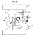
- the direction changing mechanism T includes an actuator-side rack r1 provided on the linear motion member h2 which performs the linear motion of the actuator A, a damper-side rack r2 provided at one end of the hydraulic damper D, and a gear G disposed between the actuator-side rack r1 and the damper-side rack r2 and meshing with both racks.
- the hydraulic damper D performs an extending motion
- the hydraulic damper D performs a retracting motion.
- a rotary shaft of the gear G may be installed so as to permit only movement in the vertical direction with respect to the sprung member B and the unsprung member W and inhibit movement in lateral directions, i.e., in the front and rear direction (the direction piercing through the paper surface) in Fig. 1 and in the right and left direction in Fig. 1 .
- guides g1 and g2 which are tubes or rods extending in the vertical direction in Fig. 1 are provided in the actuator A and the hydraulic damper D, respectively, and there is further provided a base portion g3 adapted to slide with respect to those guides and hold the rotary shaft of the gear G.
- the gear G is constituted by a single gear.
- a gear mechanism comprising an odd number of gears.
- the damper-side rack r2 provided in the hydraulic damper D may be installed on one of the cylinder C and the rod R. Therefore, the other of the cylinder C and the rod R may be connected to the unsprung member W. Thus, the hydraulic damper D may be interposed between the direction changing mechanism T and the unsprung member W either in an erected state or an inverted state.
- the suspension device S is further provided with a suspension spring SP interposed between the sprung member B and the unsprung member W.
- the sprung member B is supported by the suspension spring SP.
- the hydraulic damper D is connected in series with the actuator A although the direction changing mechanism T is interposed therebetween; besides, the hydraulic damper D is disposed on the unsprung member W side. Therefore, when a high-frequency vibration such as a vibration of a relatively large acceleration is inputted to the unsprung member W while the vehicle is running on a rough road or strikes on a projection on a road surface, the hydraulic damper D absorbs this vibration energy and acts to make the transmission of the vibration to the actuator A side difficult, coupled with the foregoing vibration transfer suppressing effect obtained by biasing means.
- the actuator A Upon this upward movement of the hydraulic damper D, the actuator A is moved in the opposite, downward direction by the direction changing mechanism T. At this time, the rotor of the motor M and the rotating member h1 in the actuator A are large in the moment of inertia, and even if the extension or retraction of the actuator A is impeded by the moment of inertia, the suspension device S retracts as a whole by virtue of the above operation.
- the actuator A Upon this downward movement of the hydraulic damper D, the actuator A is moved in the opposite, upward direction by the direction changing mechanism T. Now, the actuator A transforms the vibration as a linear motion inputted from the unsprung member W side into a rotational motion.
- the actuator A is provided with many rotating members, the inertial mass thereof is large and so is the moment of inertia against a high-frequency vibration, and the influence of friction exists. Consequently, there is provided a characteristic that the vibration on the unsprung member W side is easy to be transmitted to the sprung member B.
- the moment of inertia of the rotating member h1 is large, and particularly upon input of a high-frequency vibration, the extension or retraction of the actuator A tends to be impeded by the moment of inertia.
- the suspension device S extends as a whole.
- the vehicle body undergoes rolling and the vehicle load shifts to the outer wheel side rather than the inner wheel side.
- force acting in the direction to lift the sprung member B is created in the suspension device S disposed on the outer wheel side so as to offset lateral acceleration of the vehicle body.
- the bottom contact is apt to occur in contrast with the above operation, but, as mentioned above, the suspension device S is apt to retract and the vehicle load is shifted to the outer wheel side, so that even if the bottom contact should occur, the resulting shock is weaker than in the conventional suspension device.
- the bottom contact is apt to occur in the hydraulic damper located on the outer wheel side on which the vehicle load is increased and on which an impact tends to be large. In the suspension device S, however, the bottom contact is sure to be prevented in the hydraulic damper located on the outer wheel side.
- the suspension device S even when the vehicle strikes on a projection or passes a depression during a turning motion, not only the ride comfort in the vehicle can be improved, but also it is possible to positively prevent the bottom contact of the hydraulic damper D in the suspension device S disposed on an outer wheel side on which the vehicle load is increased, thus making it possible to improve the ride comfort in the vehicle effectively. Besides, since the bottom contact of the hydraulic damper D on the outer wheel side on which a large shock tends to be induced can be prevented, there is no fear of causing a functional deterioration of the suspension device S, so that the reliability of the suspension device S is improved to a remarkable extent.
- the vibration of the unsprung member W is difficult to be transmitted to the sprung member B since the total mass of vibration between the sprung member B and the unsprung member W can be made lighter than in the conventional damper in which the motor M itself is supported by a spring, whereby it becomes possible to further improve the ride comfort.
- the damper D is improved in its onboard-ability onto a vehicle and is thus more practicable.
- the position of the piston P in the hydraulic damper D is to be established beforehand with respect to the cylinder C, this can be done by connecting an upper end of the hydraulic damper D, or an upper end of the rod R in Fig. 1 , to an intermediate point of the suspension spring SP.
- the piston P is returned to a predetermined position with respect to the cylinder C, whereby the occurrence of a situation such that the piston P stops at an offset position with respect to the cylinder C by extension or retraction of the hydraulic damper D is prevented, thus making it possible to prevent the bottom contact of the hydraulic damper D more positively.
- springs for holding the piston P grippingly may be disposed within each of pressure chambers in the hydraulic damper D.
- springs are disposed respectively between the piston P and the upper end of the cylinder C and between the piston P and the lower end of the cylinder C to hold the piston P in a sandwiching manner.
- the piston P can be established its position with respect to the cylinder C and there can be obtained the same effect as in case of connecting the upper end of the hydraulic damper D to an intermediate position of the suspension spring SP.
- this direction changing mechanism includes a bar 1 which is allowed to rotate about a fulcrum (a).
- One end of the bar 1 is connected to the linear motion member h2 rotatably while permitting a stroke of the member h2 which performs a linear motion of the actuator A, and an opposite end of the bar 1 is rotatably connected to one end of the hydraulic damper D so as to permit extension and retraction of the hydraulic damper D.
- the bar 1 is made rotatable about the fulcrum (a) located at a central position, with elongated axial holes 2 and 3 being formed in both ends respectively of the bar 1.
- a pin 4 is provided on an end portion of the linear motion member h2 so as to be inserted into the elongated hole 2 and a pin 5 is provided on an end portion of the rod R of the hydraulic damper D so as to be inserted into the elongated hole 3.
- the fulcrum (a) may be provided so that only the vertical movement is allowed with respect to the sprung member B and the unsprung member W.
- the direction changing mechanism T1 can also function like the direction changing mechanism T described above. That is, even if the direction changing mechanism T1 is adopted, there can be obtained the foregoing function and effect of the suspension device S.
- the lever ratio can be changed by appropriately setting the position of the fulcrum (a) on the bar 1.
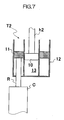
- this direction changing mechanism includes an actuator-side piston 10 connected to the linear motion member h2 of the actuator A, a damper-side piston 11 connected to one end of the rod R of the hydraulic damper D, a changing cylinder 12 into which the actuator-side piston 10 and the damper-side piston 11 are slidably inserted, and a chamber 13 filled with fluid, the chamber 13 being defined by both actuator-side piston 10 and damper-side piston 11 within the changing cylinder 12.
- the changing cylinder 12 is formed in a cylindrical U shape so that open ends thereof face in the same direction, and the actuator-side piston 10 and the damper-side piston 11 are inserted into the changing cylinder 12 from both open ends respectively of the cylinder to define the chamber 13 within the cylinder.
- the changing cylinder 12 may be installed so as to permit only the vertical movement with respect to the sprung member B and the unsprung member W.
- the direction changing mechanism T2 can also function like the direction changing mechanism T described above. That is, even if the direction changing mechanism T2 is adopted, there can be obtained the foregoing function and effect of the suspension device S.
- the changing cylinder 12 is disposed with its open ends facing upwards in Fig. 5 , the top and the bottom may be reversed, that is, the cylinder 12 may be disposed with its open ends facing downwards.
- the rod R or the cylinder C in connecting the damper-side piston 11 with the rod R or the cylinder C in the hydraulic damper D, the rod R or the cylinder C may be connected to the damper-side piston 11 so as to pass through the chamber 13.
- the changing cylinder 12 may be formed in such a double cylinder shape as shown in Fig. 7 .
- a hydraulic damper D1 includes a first cylinder 20, a second cylinder 21 disposed in parallel with the first cylinder 20, an actuator-side piston 23 connected to the linear motion member h2 of the actuator A and inserted slidably into the first cylinder 20 to define a first chamber 22 within the first cylinder 20, a vehicle-side piston 25 connected to the unsprung member W and inserted slidably into the second cylinder 21 to define a second chamber 24 within the second cylinder 21, a passage 26 which provides communication between the first chamber 22 and the second chamber 24 in such a manner that the moving direction of the actuator-side piston 23 and that of the vehicle-side piston 25 are opposite to each other, and a damping force generating element 27 disposed in the passage 26.
- the first chamber 22 and the second chamber 24 are filled with liquid such as working fluid.
- first cylinder 20 and the second cylinder 21 are formed in a cylindrical shape and are connected in parallel with each other. Openings of both the first cylinder 20 and the second cylinder 21 face upward in Fig. 8 .
- the actuator-side piston 23 is inserted into the first cylinder 20 from the open end of the same cylinder to form the first chamber 22 in a lower portion of the first cylinder 20, while the vehicle-side piston 25 is inserted into the second cylinder 21 from the open end of the same cylinder to form the second chamber 24 in a lower portion of the second cylinder 21.
- the first chamber 22 and the second chamber 23 are brought into communication with each other through the passage 26.
- the hydraulic damper D1 functions as both a damping force generation source and a direction changing mechanism and hence can function in the same manner as the foregoing hydraulic damper D and direction changing mechanism T. Accordingly, there are obtained the foregoing function and effect of the suspension device S.
- first cylinder 20 and the second cylinder 21 are disposed with their open ends facing upwards in Fig. 8
- the top and the bottom may be reversed, that is, both cylinders may be disposed with their open ends facing downwards.
- Fig. 9 There may be adopted such an arrangement as shown in Fig. 9 , in which the open ends of the first cylinder 20 and the second cylinder 21 are alternated, and the first chamber 22 is disposed in a lower portion of the first cylinder 20, while the second chamber 24 is disposed in an upper portion of the second cylinder 21, and the first chamber 22 and the second chamber 24 are put in communication with each other through the passage 26.
- a rod-like member extending from the sprung member B or the unsprung member W while passing through the second chamber 24 may be connected to the vehicle-side piston 25.
- the hydraulic damper D1 may be formed in a double cylinder shape as shown in Fig. 10 .
- the suspension device of the present invention is applicable to a vehicular suspension.
Landscapes
- Engineering & Computer Science (AREA)
- Mechanical Engineering (AREA)
- General Engineering & Computer Science (AREA)
- Physics & Mathematics (AREA)
- Acoustics & Sound (AREA)
- Aviation & Aerospace Engineering (AREA)
- Vehicle Body Suspensions (AREA)
- Vibration Prevention Devices (AREA)
Applications Claiming Priority (2)
| Application Number | Priority Date | Filing Date | Title |
|---|---|---|---|
| JP2006277504A JP2008094226A (ja) | 2006-10-11 | 2006-10-11 | サスペンション装置 |
| PCT/JP2007/068330 WO2008044448A1 (fr) | 2006-10-11 | 2007-09-13 | Dispositif de suspension |
Publications (2)
| Publication Number | Publication Date |
|---|---|
| EP2060417A1 true EP2060417A1 (fr) | 2009-05-20 |
| EP2060417A4 EP2060417A4 (fr) | 2009-12-09 |
Family
ID=39282653
Family Applications (1)
| Application Number | Title | Priority Date | Filing Date |
|---|---|---|---|
| EP07807681A Withdrawn EP2060417A4 (fr) | 2006-10-11 | 2007-09-13 | Dispositif de suspension |
Country Status (4)
| Country | Link |
|---|---|
| US (1) | US20100117277A1 (fr) |
| EP (1) | EP2060417A4 (fr) |
| JP (1) | JP2008094226A (fr) |
| WO (1) | WO2008044448A1 (fr) |
Cited By (8)
| Publication number | Priority date | Publication date | Assignee | Title |
|---|---|---|---|---|
| WO2011064031A1 (fr) * | 2009-11-25 | 2011-06-03 | Robert Bosch Gmbh | Amortisseur de vibration commandé |
| EP2236324A3 (fr) * | 2009-04-03 | 2011-07-06 | Schaeffler Technologies AG & Co. KG | Dispositif de réglage en hauteur pour suspensions de roues de véhicules automobiles |
| CN102666027A (zh) * | 2009-11-25 | 2012-09-12 | 罗伯特·博世有限公司 | 电动工具中的振荡装置的固有频率的改变 |
| WO2013104437A1 (fr) * | 2012-01-09 | 2013-07-18 | Centrum Badawczo-Rozwojowe "Epar" Sp. Z O.O. | Dispositif et procédé de commande de forces fictives dans des ensembles dynamiques non linéaires |
| WO2013105868A1 (fr) * | 2012-01-09 | 2013-07-18 | Centrum Badawczo-Rozwojowe "Epar" Sp. Z O.O. | Procédé et dispositif pour emmagasiner l'énergie cinétique d'impact |
| WO2014006475A1 (fr) * | 2012-07-03 | 2014-01-09 | Epar Sp. Z O. O. | Siège de véhicule absorbant les chocs |
| US9334914B2 (en) | 2010-10-20 | 2016-05-10 | Bill J. Gartner | Shock absorber with inertance |
| CN111055648A (zh) * | 2019-12-31 | 2020-04-24 | 广东博智林机器人有限公司 | 主动悬挂机构、agv小车及agv小车控制方法 |
Families Citing this family (17)
| Publication number | Priority date | Publication date | Assignee | Title |
|---|---|---|---|---|
| JP4590028B2 (ja) * | 2008-11-18 | 2010-12-01 | 株式会社エーシーシー | 車高調整懸架装置 |
| JP5424751B2 (ja) * | 2009-07-10 | 2014-02-26 | カヤバ工業株式会社 | サスペンション装置 |
| US20110030471A1 (en) * | 2009-08-07 | 2011-02-10 | Teruo Maeda | Oscillation control device |
| US8541895B2 (en) * | 2009-10-05 | 2013-09-24 | Honda Motor Co., Ltd. | Energy regenerating damper |
| DE102010035088A1 (de) * | 2010-08-21 | 2012-03-08 | Audi Ag | Radaufhängung für ein Kraftfahrzeug |
| CN102642453A (zh) * | 2012-04-18 | 2012-08-22 | 杨亦勇 | 一种将频率共震应用于电动汽车动能发电的方法 |
| JP6408486B2 (ja) | 2012-12-14 | 2018-10-17 | オハイオ ユニバーシティ | リセット式半受動剛性ダンパ及びその使用方法 |
| US11353084B2 (en) * | 2013-03-15 | 2022-06-07 | Clearmotion Acquisition I Llc | Rotary actuator driven vibration isolation |
| KR101971525B1 (ko) * | 2017-12-13 | 2019-04-23 | 주식회사 만도 | 능동 회생 완충기 |
| CN108146182B (zh) * | 2018-01-03 | 2025-01-28 | 宁波市智能制造产业研究院 | 调节装置及导引车 |
| US11001119B2 (en) * | 2018-08-09 | 2021-05-11 | Ford Global Technologies, Llc | Vehicle shock absorber |
| JP6753911B2 (ja) * | 2018-11-06 | 2020-09-09 | 本田技研工業株式会社 | 減衰力可変ダンパの制御装置 |
| CN110319147B (zh) * | 2019-06-10 | 2024-08-16 | 苏州和信精密科技股份有限公司 | 一种带x型抗震结构的机柜 |
| KR102462091B1 (ko) * | 2020-10-20 | 2022-11-03 | 김태호 | 이중 실린더 타입의 무진동 쇽업소버 |
| CN114352669A (zh) * | 2021-12-23 | 2022-04-15 | 中联重科股份有限公司 | 油气悬挂系统及其刚柔性控制阀和工程车辆 |
| CN114103584B (zh) * | 2021-12-27 | 2024-08-23 | 丹东黄海汽车有限责任公司 | 一种汽车用避震器弹簧的调整机构 |
| CN114987620B (zh) * | 2022-04-28 | 2023-06-23 | 南通浩盛汽车科技有限公司 | 一种用于汽车减震的多弹簧减震器 |
Family Cites Families (25)
| Publication number | Priority date | Publication date | Assignee | Title |
|---|---|---|---|---|
| JPS5414276B2 (fr) * | 1971-10-13 | 1979-06-06 | ||
| GB1384454A (en) * | 1972-03-08 | 1975-02-19 | Automotive Prod Co Ltd | Vehicle suspension |
| JPS60209309A (ja) * | 1984-03-31 | 1985-10-21 | Nhk Spring Co Ltd | 車輛用懸架装置 |
| GB2149055B (en) * | 1983-09-26 | 1987-11-04 | Nhk Spring Co Ltd | Vehicle suspension unit with damping & spring rate adjustable |
| IT1254766B (it) * | 1992-02-05 | 1995-10-11 | Univer Spa | Attuatore pneumatico, rotativo, a doppia cremagliera con ammortizzatore in contropressione. |
| JPH07276955A (ja) * | 1994-04-08 | 1995-10-24 | Nissan Motor Co Ltd | 車両用サスペンション |
| DE19543760A1 (de) * | 1995-11-24 | 1997-05-28 | Ingelheim Peter Graf Von | Schaltbare oder selbstschaltende Einrichtung zur Umschaltung der Verfahrgeschwindigkeit und -kraft an endlichen Vorschüben oder zur Kennlinienumschaltung an Federn, insbesondere mechanischen Federn |
| US6129364A (en) * | 1996-04-26 | 2000-10-10 | Fisher; Kenneth G. | Independent suspensions |
| DE19702241A1 (de) * | 1997-01-24 | 1998-02-12 | Mannesmann Sachs Ag | Fahrwerk für ein Kraftfahrzeug |
| US6098969A (en) * | 1998-08-17 | 2000-08-08 | Nagarajaiah; Satish | Structural vibration damper with continuously variable stiffness |
| JP2001180244A (ja) | 1999-12-27 | 2001-07-03 | Nissan Motor Co Ltd | 車両の姿勢制御装置 |
| US6672573B2 (en) * | 2000-06-16 | 2004-01-06 | Stefano Berton | Displacement amplification method and apparatus for passive energy dissipation in seismic applications |
| GB0116424D0 (en) * | 2001-07-04 | 2001-08-29 | Univ Cambridge Tech | Mechanical device |
| US20040074720A1 (en) * | 2002-05-07 | 2004-04-22 | Thieltges Gary Peter | Motion stabilized mounts |
| DE20209120U1 (de) * | 2002-06-12 | 2003-10-16 | Hemscheidt Fahrwerktechnik GmbH & Co., 42781 Haan | Federungseinrichtung für Kraftfahrzeuge |
| CA2410776A1 (fr) * | 2002-11-25 | 2004-05-25 | Andre Lavoie | Systeme de suspension pneumatique de levage |
| DE10317281B4 (de) * | 2003-04-11 | 2005-04-28 | Schunk Gmbh & Co Kg | Dreh- oder Schwenkvorrichtung und Anschlussmodul für eine Dreh- oder Schwenkvorrichtung |
| JP4271604B2 (ja) * | 2004-03-10 | 2009-06-03 | トヨタ自動車株式会社 | 電磁緩衝器 |
| JP4403851B2 (ja) * | 2004-03-24 | 2010-01-27 | トヨタ自動車株式会社 | 車両懸架装置 |
| DE102004017885B4 (de) * | 2004-04-13 | 2007-08-30 | Audi Ag | Radaufhängung für Kraftfahrzeuge |
| JP4393313B2 (ja) * | 2004-08-27 | 2010-01-06 | カヤバ工業株式会社 | 緩衝器 |
| JP4464798B2 (ja) * | 2004-11-24 | 2010-05-19 | トヨタ自動車株式会社 | 車両用サスペンション装置 |
| US7377529B2 (en) * | 2004-11-30 | 2008-05-27 | Trw Automotive U.S. Llc | Active roll control system for a vehicle suspension system |
| JP2006194261A (ja) * | 2005-01-11 | 2006-07-27 | Kayaba Ind Co Ltd | 緩衝装置 |
| WO2006092013A1 (fr) * | 2005-03-01 | 2006-09-08 | Kinetic Pty Ltd | Système hydraulique pour suspension de véhicule |
-
2006
- 2006-10-11 JP JP2006277504A patent/JP2008094226A/ja active Pending
-
2007
- 2007-09-13 WO PCT/JP2007/068330 patent/WO2008044448A1/fr not_active Ceased
- 2007-09-13 EP EP07807681A patent/EP2060417A4/fr not_active Withdrawn
- 2007-09-13 US US12/444,637 patent/US20100117277A1/en not_active Abandoned
Cited By (11)
| Publication number | Priority date | Publication date | Assignee | Title |
|---|---|---|---|---|
| EP2236324A3 (fr) * | 2009-04-03 | 2011-07-06 | Schaeffler Technologies AG & Co. KG | Dispositif de réglage en hauteur pour suspensions de roues de véhicules automobiles |
| WO2011064031A1 (fr) * | 2009-11-25 | 2011-06-03 | Robert Bosch Gmbh | Amortisseur de vibration commandé |
| CN102667221A (zh) * | 2009-11-25 | 2012-09-12 | 罗伯特·博世有限公司 | 受控制的振荡阻尼器 |
| CN102666027A (zh) * | 2009-11-25 | 2012-09-12 | 罗伯特·博世有限公司 | 电动工具中的振荡装置的固有频率的改变 |
| CN102666027B (zh) * | 2009-11-25 | 2015-07-22 | 罗伯特·博世有限公司 | 电动工具中的振荡装置的固有频率的改变 |
| US9334914B2 (en) | 2010-10-20 | 2016-05-10 | Bill J. Gartner | Shock absorber with inertance |
| WO2013104437A1 (fr) * | 2012-01-09 | 2013-07-18 | Centrum Badawczo-Rozwojowe "Epar" Sp. Z O.O. | Dispositif et procédé de commande de forces fictives dans des ensembles dynamiques non linéaires |
| WO2013105868A1 (fr) * | 2012-01-09 | 2013-07-18 | Centrum Badawczo-Rozwojowe "Epar" Sp. Z O.O. | Procédé et dispositif pour emmagasiner l'énergie cinétique d'impact |
| WO2014006475A1 (fr) * | 2012-07-03 | 2014-01-09 | Epar Sp. Z O. O. | Siège de véhicule absorbant les chocs |
| CN111055648A (zh) * | 2019-12-31 | 2020-04-24 | 广东博智林机器人有限公司 | 主动悬挂机构、agv小车及agv小车控制方法 |
| CN111055648B (zh) * | 2019-12-31 | 2021-05-18 | 广东博智林机器人有限公司 | 主动悬挂机构、agv小车及agv小车控制方法 |
Also Published As
| Publication number | Publication date |
|---|---|
| US20100117277A1 (en) | 2010-05-13 |
| JP2008094226A (ja) | 2008-04-24 |
| WO2008044448A1 (fr) | 2008-04-17 |
| EP2060417A4 (fr) | 2009-12-09 |
Similar Documents
| Publication | Publication Date | Title |
|---|---|---|
| EP2060417A1 (fr) | Dispositif de suspension | |
| EP2012042B1 (fr) | Amortisseur | |
| EP2231427B1 (fr) | Ensemble jambe de force pour des suspensions de roue de véhicules automobiles | |
| US10328762B2 (en) | Electric damper for vehicle | |
| CN105008155B (zh) | 用于机动车辆的悬挂组件以及包括该悬挂组件的机动车辆 | |
| CN102472358B (zh) | 减振器装置 | |
| US8070169B2 (en) | Actuator for active roll control system | |
| CN101698416A (zh) | 一种辅助回正及极限阻尼式转向器 | |
| CN110001344B (zh) | 一种主动抬升扭转梁悬架结构 | |
| JP2011012785A (ja) | サスペンション装置 | |
| CN221162073U (zh) | 车辆的减振器总成和悬架系统、车辆 | |
| JP4403851B2 (ja) | 車両懸架装置 | |
| JPS62251220A (ja) | 緩衝器 | |
| JP5421846B2 (ja) | サスペンション装置 | |
| CN214295554U (zh) | 一体化减震舵轮驱动系统 | |
| JPH03200417A (ja) | ロールダンパ装置 | |
| JP2008303963A (ja) | 電磁式ショックアブソーバ | |
| CN203979307U (zh) | 用于汽车悬架的新型惯性元装置 | |
| CN223178045U (zh) | 一种用于车辆减振器的液压缓冲和限位机构 | |
| JP5122315B2 (ja) | 緩衝器 | |
| CN111483278B (zh) | 一种垂直向缓冲的一体式悬挂-转向机构 | |
| KR100482143B1 (ko) | 감쇠력 제어수단을 갖춘 차량용 쇽업소버 | |
| WO2014006480A1 (fr) | Dispositif d'amortissement des vibrations d'une cabine de camion | |
| KR100586249B1 (ko) | 스트로크 감응형 쇽업소버 | |
| JPH112279A (ja) | 車両用ダンパ |
Legal Events
| Date | Code | Title | Description |
|---|---|---|---|
| PUAI | Public reference made under article 153(3) epc to a published international application that has entered the european phase |
Free format text: ORIGINAL CODE: 0009012 |
|
| 17P | Request for examination filed |
Effective date: 20090326 |
|
| AK | Designated contracting states |
Kind code of ref document: A1 Designated state(s): AT BE BG CH CY CZ DE DK EE ES FI FR GB GR HU IE IS IT LI LT LU LV MC MT NL PL PT RO SE SI SK TR |
|
| AX | Request for extension of the european patent |
Extension state: AL BA HR MK RS |
|
| A4 | Supplementary search report drawn up and despatched |
Effective date: 20091105 |
|
| RIC1 | Information provided on ipc code assigned before grant |
Ipc: F16F 15/03 20060101ALI20091030BHEP Ipc: F16F 9/26 20060101ALI20091030BHEP Ipc: B60G 17/015 20060101ALI20091030BHEP Ipc: B60G 17/08 20060101ALI20091030BHEP Ipc: B60G 17/00 20060101ALI20091030BHEP Ipc: B60G 13/18 20060101AFI20091030BHEP |
|
| RIN1 | Information on inventor provided before grant (corrected) |
Inventor name: KONDO, TAKUHIRO Inventor name: OHTA, YASUHIRO |
|
| 17Q | First examination report despatched |
Effective date: 20100208 |
|
| STAA | Information on the status of an ep patent application or granted ep patent |
Free format text: STATUS: THE APPLICATION IS DEEMED TO BE WITHDRAWN |
|
| 18D | Application deemed to be withdrawn |
Effective date: 20100619 |