EP2060426A1 - Capote pour vehicule de type cabriolet - Google Patents
Capote pour vehicule de type cabriolet Download PDFInfo
- Publication number
- EP2060426A1 EP2060426A1 EP20080019893 EP08019893A EP2060426A1 EP 2060426 A1 EP2060426 A1 EP 2060426A1 EP 20080019893 EP20080019893 EP 20080019893 EP 08019893 A EP08019893 A EP 08019893A EP 2060426 A1 EP2060426 A1 EP 2060426A1
- Authority
- EP
- European Patent Office
- Prior art keywords
- hood according
- drive
- designed
- connecting elements
- vehicle
- Prior art date
- Legal status (The legal status is an assumption and is not a legal conclusion. Google has not performed a legal analysis and makes no representation as to the accuracy of the status listed.)
- Granted
Links
- 239000004744 fabric Substances 0.000 claims abstract description 9
- 230000001360 synchronised effect Effects 0.000 claims description 7
- 230000005540 biological transmission Effects 0.000 claims description 5
- 230000008878 coupling Effects 0.000 description 5
- 238000010168 coupling process Methods 0.000 description 5
- 238000005859 coupling reaction Methods 0.000 description 5
- 230000008901 benefit Effects 0.000 description 4
- 238000006243 chemical reaction Methods 0.000 description 3
- 230000003111 delayed effect Effects 0.000 description 2
- 240000001439 Opuntia Species 0.000 description 1
- 235000004727 Opuntia ficus indica Nutrition 0.000 description 1
- 238000005266 casting Methods 0.000 description 1
- 238000010276 construction Methods 0.000 description 1
- 238000010586 diagram Methods 0.000 description 1
- 230000000694 effects Effects 0.000 description 1
- 238000011990 functional testing Methods 0.000 description 1
- 230000010354 integration Effects 0.000 description 1
- 230000003993 interaction Effects 0.000 description 1
- 238000002955 isolation Methods 0.000 description 1
- 238000004519 manufacturing process Methods 0.000 description 1
- 238000000034 method Methods 0.000 description 1
- 230000002441 reversible effect Effects 0.000 description 1
- 230000007480 spreading Effects 0.000 description 1
- 238000003892 spreading Methods 0.000 description 1
Images



Classifications
-
- B—PERFORMING OPERATIONS; TRANSPORTING
- B60—VEHICLES IN GENERAL
- B60J—WINDOWS, WINDSCREENS, NON-FIXED ROOFS, DOORS, OR SIMILAR DEVICES FOR VEHICLES; REMOVABLE EXTERNAL PROTECTIVE COVERINGS SPECIALLY ADAPTED FOR VEHICLES
- B60J7/00—Non-fixed roofs; Roofs with movable panels, e.g. rotary sunroofs
- B60J7/02—Non-fixed roofs; Roofs with movable panels, e.g. rotary sunroofs of sliding type, e.g. comprising guide shoes
- B60J7/04—Non-fixed roofs; Roofs with movable panels, e.g. rotary sunroofs of sliding type, e.g. comprising guide shoes with rigid plate-like element or elements, e.g. open roofs with harmonica-type folding rigid panels
- B60J7/057—Driving or actuating arrangements e.g. manually operated levers or knobs
- B60J7/0573—Driving or actuating arrangements e.g. manually operated levers or knobs power driven arrangements, e.g. electrical
Definitions
- the invention relates to a hood of a convertible vehicle, which is displaceable between a passenger compartment releasing position and the passenger compartment spanning position, according to the closer defined in the preamble of claim 1.
- a convertible vehicle with a folding top and a linkage for spreading and folding the hood known.
- a reversible motor is provided for actuating the linkage.
- a connecting rod or a flexible shaft is provided which connects the output shafts of the motors.
- a hood of a convertible vehicle which is displaceable between a passenger compartment releasing position and the passenger compartment spanning position to create, which allows a simple and secure way synchronous on both sides of the vehicle harmonious and low-wear top movement and at the same time a great constructive freedom allowed in the design of the top and adjacent areas of the vehicle.
- a hood of a convertible vehicle which is displaceable between a passenger compartment releasing position and the passenger compartment spanning position, wherein each vehicle side at least one drive device is assigned to top movement, and wherein a top movement by means of at least one cooperating with the drive means mechanical Connection device is synchronized.
- the connecting device is arranged in or on a vehicle width spanning element of the top.
- An inventive soft top of a convertible vehicle has the advantage that the synchronizing connection device, which can be arranged in many ways in or on crossbeams or other vehicle width spanning roof elements including loops of a top cloth, with this arrangement can be stored to save space and invisible from the outside ,
- the synchronizing connection device can be z. B. by an integration of guides and channels in profiles and castings of crossbeams or comparable top elements inconspicuous adapted to the local spatial conditions and follow as a flexible wave exactly the contour of the adjacent top element.
- a drive formed with such a synchronizing connection device is also particularly advantageous in a hood system which can be preassembled as a module.
- a full floor level functional test may be performed outside the vehicle prior to the top assembly if necessary.
- a possibly present non-synchronism of the two drive devices can be compensated for each other, wherein the slower drive device is supported by the faster drive device or the faster drive device is delayed by the slower drive device.
- a proposed top can also be easily compensated by the synchronizing connection means large tolerances of the individual drives with respect to a speed and torque and even in very compliant systems such.
- drives for a top cloth holding bracket in unstable covering of convertible vehicles, or in soft top or trunk lid drives a harmonious total topping be ensured.
- Compared with electronically synchronized drives synchronization according to the invention has the advantage that no electromagnetic interference can occur.
- a solution according to the invention enables a very simple and fast conversion to an unsynchronized operation, if desired.
- the synchronizing connection device in or on a fabric strap spanning the vehicle width or a transverse element spanning the vehicle width, z. B. a bow or other moving during a top movement components is arranged.
- the choice of the arrangement of the connecting device, the expert can choose flexibly depending on the type of convertible vehicle and the nature of the respective top.
- connection device interacts mechanically with the drive devices designed in particular as electric motors and is therefore coupled directly to the drive devices.
- the synchronizing connection means is connected via at least one, for example, flanged to the corresponding drive means transmission device with the drive means.
- the speed acting on the connecting device and the torque acting on the connecting device differ.
- the drive means operate in different directions of rotation, wherein the synchronizing connection means can be used exclusively for synchronization of the drive means and arranged integrally between the drive means.
- connection device in each case has a connection element interacting with a drive device, wherein the mutually facing ends of the connection elements are designed such that the connection elements are rotatable relative to each other in a different direction of rotation
- drive devices of identical construction can advantageously be used with an identical drive direction.
- a very simple direction of rotation reversal by the connecting device can be realized in that the connecting device in each case has a cooperating with a drive means connecting element, wherein at least the mutually facing ends of the connecting elements are formed such that arranged over a mutually facing ends of the connecting elements Gear element reversal of rotation of the two connecting elements is implemented.
- the connecting elements of the connecting device in a simple embodiment of the invention at the mutually facing ends of the connecting elements on a rack member.
- the gear element can interact directly with the connecting elements.
- the connecting device may be formed as a flexible rotation device, wherein it may be formed in one alternative embodiment of the invention with one or more rigid shafts.
- An inventive hood is operable in an advantageous embodiment of the invention by means of an emergency operating device, in particular in the event of failure of at least one drive device. Due to the synchronous drive of the top even during the emergency actuation movement acting on the uniformly moving kinematic actuation forces are advantageously low, so that such emergency operation can be safely performed in relation to the load and durability of the components involved.
- At least one drive means is designed as an electric motor, wherein the electric motor initiates a drive torque directly into at least one hinge of the hood.
- An inventive convertible top of a convertible vehicle can advantageously be designed both as a soft-top top and as a hard-top top and is therefore versatile.
- Fig. 1 is a convertible vehicle 1 shown with a presently designed as a soft-top top 3, wherein the hood 3 is shown in a passenger compartment 5 spanning closed position.
- the Fig. 2 shows a left half of a top linkage 7 of the top 3 also in a closed position, which is formed substantially mirror-inverted to a right half of the top linkage 7.
- the convertible top linkage 7 can be arranged in a front region on a windshield frame 8 of the convertible vehicle 1 and has a plurality of transverse elements, which span a vehicle width and form a bow 13, which are arranged in particular on side rails 15 of the convertible top linkage 7.
- a rear window 10 is arranged in a lower area on a fabric support bar 12 of the top linkage 7, which likewise spans the entire vehicle width.
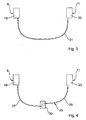
- the top linkage 7 is pivotally mounted in a rearward region of the top 3 to a main bearing 17 and can by means of two in the FIG. 3 and FIG. 4 apparent, designed as electric motors 9, 11 drive means from the illustrated closed position into a passenger compartment 5 releasing open position and vice versa are transferred.
- the apparent electric motor 9 cooperates with a transmission device designed as a gear stage 19, by means of which a drive torque of the electric motor 9 can be transmitted to the hood linkage 7.
- the electric motors 9 and 11 must work synchronously, for this purpose a designed as a flexible rotary shaft 21 mechanical connection means is provided which with the gear stage 19 of the left side of the vehicle and designed as a gear stage 23 gear means of the right electric motor 11 is coupled.
- the gear stages 19 and 23 each have a connection for receiving the flexible rotary shaft 21, so that the flexible rotary shaft 21 can be mechanically and positively coupled to the respective gear stage 19 and 23, respectively. If the flexible rotary shaft 21 is connected to both gear stages 19 and 23, the electric motors 9 and 11 are also positively coupled via the flexible rotary shaft 21. A slower than the other electric motor 9 or 11 working electric motor 11 or 9 'is thereby by the faster electric motor 9 and 11 respectively supports or is the faster electric motor 9 or 11 delayed by the slower electric motor 11 and 9 respectively.
- a coupling which is remote from the engine or driven in the direction of the output has the advantage that the noise generated by the connecting device is very small due to the low rotational speeds present in this case.
- the large forces and torques that are present cause a relatively massive design of the connecting device.
- Fig. 2 It can be seen that the flexible rotary shaft 21 extends from its coupling with the gear stage 19 of the left electric motor 9 in the direction of the fabric support bracket 12 of the top linkage 7.
- the flexible rotary shaft 21 is then guided within a hollow profile of the Stoffhaltebügels 12 on the other side of the vehicle to their arrangement on the gear stage 23 of the right electric motor 11, whereby the flexible rotary shaft 21 in a very simple, protected and space-saving manner between the gear stages 19, 23 of the Electric motors 9, 11 runs.
- the flexible rotation shaft is arranged on the fabric support bracket or on or in a bow of the top makes a connection between each one side of the vehicle associated electric motors.
- the connecting device can also be provided to arrange the connecting device on or in other vehicle width spanning elements of the convertible vehicle.
- Connecting devices can also be used in the case of roofs which have a plurality of electric motors on each side of the vehicle.
- each swivel joint for example, for power and / or space reasons own drive device may be assigned with one or more gear stages.
- the drive devices arranged at corresponding locations on opposite vehicle sides can be connected to a connection device.
- the connecting devices may for example be arranged on or in transverse elements of the top, such as transverse spars or mirrors, and connect the drive means either directly or via joint stages.
- Fig. 3 are the gear stages 19 and 23 of the electric motors 9 and 11 shown greatly simplified.
- the electric motors 9 and 11 are formed in this embodiment in such a way that they have an opposite direction of rotation.
- the flexible rotary shaft 21 can thus, as in the Fig. 3 represented advantageously be formed easily with the integrally formed flexible rotary shaft 21.
- Fig. 4 is essentially the one in the Fig. 3 illustrated arrangement of the electric motors 9 and 11, however, these are in this case designed so that they are the same Have direction of rotation.
- a the transmission stages 19 and 23 coupling flexible rotary shaft 25 must accomplish a reversal of direction in this case.
- the flexible rotary shaft 25 has a connecting element arranged on the left-hand gear step 19 and designed as a first flexible partial shaft 27, and a connecting element arranged on the right-hand gear step 23 and designed as a second flexible partial shaft 29.
- the flexible rotary shaft 25 has a rotation-converting device 30, so that the rotational-speed conversion between the electric motors 9 and 11 is converted by the flexible rotary shaft 25.
- the flexible part shafts 27 and 29 at their ends facing each other for Drehsinnwandlung in each case a gear 31 and 33, wherein the gears 31 and 33 are mounted such that they engage with each other.
- the flexible part shafts 27 and 29 thus rotate in the opposite direction of rotation and ensure the rotation sense conversion.
- the rotational direction converting device 30 has a toothed wheel element designed as a toothed wheel 35, which is in engagement with the mutually facing ends of the flexible partial shafts 27 and 29.
- the ends of the flexible part shafts 27 and 29 are each formed with a rack member 37 and 39, wherein the rack members 37 and 39 and the gear 35 are mounted in the Drehsinnwandlungs vibration 30 such that the rack members 37 and 39 of the flexible part shafts 27 and 29 with the gear 35 are engaged so that a movement of a partial shaft 27 and 29 in a movement of the other partial shaft 29 or 27 results.
- the partial shafts are designed as pitch cables, so that the mutually facing ends of the pitch cables are directly in engagement with the gear of the rotational transmission device.
- an emergency operating device not shown, by means of which the top 3 can be moved in a failure of at least one drive means 9 and 11 respectively.
- the emergency control device can according to the in the US 4,695,089 Al Be disclosed trained emergency operation.
Landscapes
- Engineering & Computer Science (AREA)
- Mechanical Engineering (AREA)
- Superstructure Of Vehicle (AREA)
Applications Claiming Priority (1)
| Application Number | Priority Date | Filing Date | Title |
|---|---|---|---|
| DE102007054946A DE102007054946A1 (de) | 2007-11-17 | 2007-11-17 | Verdeck eines Cabriolet-Fahrzeugs |
Publications (2)
| Publication Number | Publication Date |
|---|---|
| EP2060426A1 true EP2060426A1 (fr) | 2009-05-20 |
| EP2060426B1 EP2060426B1 (fr) | 2015-11-11 |
Family
ID=40339667
Family Applications (1)
| Application Number | Title | Priority Date | Filing Date |
|---|---|---|---|
| EP08019893.0A Not-in-force EP2060426B1 (fr) | 2007-11-17 | 2008-11-14 | capote pour vehicule de type cabriolet |
Country Status (2)
| Country | Link |
|---|---|
| EP (1) | EP2060426B1 (fr) |
| DE (1) | DE102007054946A1 (fr) |
Families Citing this family (3)
| Publication number | Priority date | Publication date | Assignee | Title |
|---|---|---|---|---|
| DE102010020591A1 (de) * | 2010-05-14 | 2011-11-17 | Fraunhofer-Gesellschaft zur Förderung der angewandten Forschung e.V. | Plasmagenerator sowie Verfahren zur Erzeugung und Anwendung eines ionisierten Gases |
| DE102013103428B4 (de) | 2013-04-05 | 2023-11-16 | Webasto-Edscha Cabrio GmbH | Betätigungseinrichtung für ein verstellbares Verdecksystem eines Kraftfahrzeugs |
| DE102013206606B4 (de) * | 2013-04-12 | 2019-10-17 | Magna Car Top Systems Gmbh | Anordnung zur Verdeckbewegung |
Citations (7)
| Publication number | Priority date | Publication date | Assignee | Title |
|---|---|---|---|---|
| US2770489A (en) | 1951-09-01 | 1956-11-13 | Gen Motors Corp | Vehicle folding top structure and power actuating means therefor |
| US4695089A (en) | 1985-02-18 | 1987-09-22 | Mazda Motor Corporation | Upper body structure of an open-top vehicle |
| US5785375A (en) * | 1993-12-29 | 1998-07-28 | Asc Incorporated | Retractable hard-top for an automotive vehicle |
| DE20210763U1 (de) * | 2002-07-17 | 2003-11-27 | Wilhelm Karmann Gmbh | Cabriolet-Fahrzeug |
| US6695385B1 (en) * | 2003-03-31 | 2004-02-24 | Asc Incorporated | Vehicle convertible roof |
| US20040051343A1 (en) * | 2002-09-18 | 2004-03-18 | Todd Grubbs | Vehicle convertible roof |
| US20040104605A1 (en) * | 2001-05-29 | 2004-06-03 | Stephen Doncov | Automotive vehicle with open air system |
Family Cites Families (6)
| Publication number | Priority date | Publication date | Assignee | Title |
|---|---|---|---|---|
| DE102004030710A1 (de) * | 2004-06-25 | 2006-01-19 | Daimlerchrysler Ag | Vorrichtung zum Antrieb eines Faltverdecks |
| DE102004044032A1 (de) * | 2004-09-09 | 2006-03-16 | Wilhelm Karmann Gmbh | Cabriolet-Fahrzeug |
| DE102004044020A1 (de) * | 2004-09-09 | 2006-03-16 | Wilhelm Karmann Gmbh | Cabriolet-Fahrzeug |
| DE102004051851A1 (de) * | 2004-10-26 | 2006-04-27 | Wilhelm Karmann Gmbh | Cabrioletverdecksystem mit wenigstens zwei Dachteilen |
| DE102005020555A1 (de) * | 2005-03-07 | 2006-09-28 | Wilhelm Karmann Gmbh | Vorrichtung zur Betätigung bewegbarer Fahrzeugaussenelemente |
| DE102006005367B9 (de) * | 2006-02-03 | 2008-05-21 | Edscha Cabrio-Dachsysteme Gmbh | Verdeck für ein Cabriolet-Fahrzeug |
-
2007
- 2007-11-17 DE DE102007054946A patent/DE102007054946A1/de not_active Withdrawn
-
2008
- 2008-11-14 EP EP08019893.0A patent/EP2060426B1/fr not_active Not-in-force
Patent Citations (7)
| Publication number | Priority date | Publication date | Assignee | Title |
|---|---|---|---|---|
| US2770489A (en) | 1951-09-01 | 1956-11-13 | Gen Motors Corp | Vehicle folding top structure and power actuating means therefor |
| US4695089A (en) | 1985-02-18 | 1987-09-22 | Mazda Motor Corporation | Upper body structure of an open-top vehicle |
| US5785375A (en) * | 1993-12-29 | 1998-07-28 | Asc Incorporated | Retractable hard-top for an automotive vehicle |
| US20040104605A1 (en) * | 2001-05-29 | 2004-06-03 | Stephen Doncov | Automotive vehicle with open air system |
| DE20210763U1 (de) * | 2002-07-17 | 2003-11-27 | Wilhelm Karmann Gmbh | Cabriolet-Fahrzeug |
| US20040051343A1 (en) * | 2002-09-18 | 2004-03-18 | Todd Grubbs | Vehicle convertible roof |
| US6695385B1 (en) * | 2003-03-31 | 2004-02-24 | Asc Incorporated | Vehicle convertible roof |
Also Published As
| Publication number | Publication date |
|---|---|
| EP2060426B1 (fr) | 2015-11-11 |
| DE102007054946A1 (de) | 2009-05-20 |
Similar Documents
| Publication | Publication Date | Title |
|---|---|---|
| DE69810193T2 (de) | Zusammenklappbare Struktur eines Hard-Tops für ein Cabriofahrzeug | |
| DE10205144B4 (de) | Verriegelungsvorrichtung für ein Faltdach eines Fahrzeugs | |
| EP1275543B1 (fr) | Dispositif de couverture pour compartiment de stockage de capote | |
| EP2451665B1 (fr) | Dispositif de toit ouvrant, en particulier pour un véhicule automobile | |
| EP2459432B1 (fr) | Système modulaire et procédé de fabrication d'un module de toit | |
| AT515896A1 (de) | Schwenkschiebetürmodul mit zentraler Funktionsanbindung | |
| EP2060426B1 (fr) | capote pour vehicule de type cabriolet | |
| EP1920962B1 (fr) | Capote pour un véhicule automobile, en particulier pour un véhicule de type cabriolet, avec un toit pliant | |
| DE4129850C1 (fr) | ||
| DE10159537A1 (de) | Vorrichtung zum Entriegeln/Verriegeln und Öffnen/Schließen einer Fahrzeugklappe | |
| EP1813457B1 (fr) | Cinématique de toit pour un toit de véhicule cabriolet | |
| EP1716013B1 (fr) | Dispositif pour actionner au moins un element exterieur pivotant d'un vehicule | |
| EP2357103B1 (fr) | Verrouillage pour un couvercle pour un véhicule de type cabriolet | |
| EP1789275B1 (fr) | Vehicule cabriolet | |
| EP1794013B1 (fr) | Vehicule cabriolet | |
| WO2021239327A1 (fr) | Module de toit pour des véhicules, système modulaire pour un module de toit et toit de véhicule | |
| DE10331144B4 (de) | Fahrzeugdach mit einem bewegbar gelagerten und verriegelbaren Dachbauteil | |
| EP3822105A1 (fr) | Véhicule cabriolet | |
| AT528319B1 (de) | Anordnung aus Antriebsvorrichtung und Scharnier | |
| DE102013009083A1 (de) | Dachmodul für ein Fahrzeugdach | |
| DE102010004963B4 (de) | Antriebseinrichtung für verstellbare Funktionseinheiten eines Cabriolets | |
| DE10213549B4 (de) | Cabriolet-Fahrzeug mit mehrteiligem Verdeck | |
| DE102005040837B4 (de) | Antriebsvorrichtung für zumindest ein bewegbares Fahrzeugteil | |
| WO2023046435A1 (fr) | Dispositif de déplacement pour déplacer une porte de véhicule et porte de véhicule | |
| DE102008035099A1 (de) | Antrieb für eine schwenkbare Frontscheibe |
Legal Events
| Date | Code | Title | Description |
|---|---|---|---|
| PUAI | Public reference made under article 153(3) epc to a published international application that has entered the european phase |
Free format text: ORIGINAL CODE: 0009012 |
|
| AK | Designated contracting states |
Kind code of ref document: A1 Designated state(s): AT BE BG CH CY CZ DE DK EE ES FI FR GB GR HR HU IE IS IT LI LT LU LV MC MT NL NO PL PT RO SE SI SK TR |
|
| AX | Request for extension of the european patent |
Extension state: AL BA MK RS |
|
| 19U | Interruption of proceedings before grant |
Effective date: 20090629 |
|
| 19W | Proceedings resumed before grant after interruption of proceedings |
Effective date: 20101201 |
|
| 17P | Request for examination filed |
Effective date: 20101201 |
|
| 17Q | First examination report despatched |
Effective date: 20110119 |
|
| AKX | Designation fees paid |
Designated state(s): AT DE FR |
|
| RAP1 | Party data changed (applicant data changed or rights of an application transferred) |
Owner name: VALMET AUTOMOTIVE OY |
|
| GRAP | Despatch of communication of intention to grant a patent |
Free format text: ORIGINAL CODE: EPIDOSNIGR1 |
|
| INTG | Intention to grant announced |
Effective date: 20150529 |
|
| GRAS | Grant fee paid |
Free format text: ORIGINAL CODE: EPIDOSNIGR3 |
|
| GRAA | (expected) grant |
Free format text: ORIGINAL CODE: 0009210 |
|
| AK | Designated contracting states |
Kind code of ref document: B1 Designated state(s): AT DE FR |
|
| REG | Reference to a national code |
Ref country code: AT Ref legal event code: REF Ref document number: 760259 Country of ref document: AT Kind code of ref document: T Effective date: 20151215 |
|
| REG | Reference to a national code |
Ref country code: DE Ref legal event code: R096 Ref document number: 502008013555 Country of ref document: DE |
|
| REG | Reference to a national code |
Ref country code: FR Ref legal event code: PLFP Year of fee payment: 8 |
|
| REG | Reference to a national code |
Ref country code: DE Ref legal event code: R097 Ref document number: 502008013555 Country of ref document: DE |
|
| PLBE | No opposition filed within time limit |
Free format text: ORIGINAL CODE: 0009261 |
|
| STAA | Information on the status of an ep patent application or granted ep patent |
Free format text: STATUS: NO OPPOSITION FILED WITHIN TIME LIMIT |
|
| 26N | No opposition filed |
Effective date: 20160812 |
|
| REG | Reference to a national code |
Ref country code: AT Ref legal event code: MM01 Ref document number: 760259 Country of ref document: AT Kind code of ref document: T Effective date: 20151114 |
|
| REG | Reference to a national code |
Ref country code: FR Ref legal event code: PLFP Year of fee payment: 9 |
|
| PG25 | Lapsed in a contracting state [announced via postgrant information from national office to epo] |
Ref country code: AT Free format text: LAPSE BECAUSE OF NON-PAYMENT OF DUE FEES Effective date: 20151114 |
|
| PGFP | Annual fee paid to national office [announced via postgrant information from national office to epo] |
Ref country code: FR Payment date: 20170130 Year of fee payment: 9 Ref country code: DE Payment date: 20170125 Year of fee payment: 9 |
|
| REG | Reference to a national code |
Ref country code: DE Ref legal event code: R119 Ref document number: 502008013555 Country of ref document: DE |
|
| REG | Reference to a national code |
Ref country code: FR Ref legal event code: ST Effective date: 20180731 |
|
| PG25 | Lapsed in a contracting state [announced via postgrant information from national office to epo] |
Ref country code: FR Free format text: LAPSE BECAUSE OF NON-PAYMENT OF DUE FEES Effective date: 20171130 Ref country code: DE Free format text: LAPSE BECAUSE OF NON-PAYMENT OF DUE FEES Effective date: 20180602 |