EP2060662A2 - Dispositif MBE et son procédé de fonctionnement - Google Patents
Dispositif MBE et son procédé de fonctionnement Download PDFInfo
- Publication number
- EP2060662A2 EP2060662A2 EP08019625A EP08019625A EP2060662A2 EP 2060662 A2 EP2060662 A2 EP 2060662A2 EP 08019625 A EP08019625 A EP 08019625A EP 08019625 A EP08019625 A EP 08019625A EP 2060662 A2 EP2060662 A2 EP 2060662A2
- Authority
- EP
- European Patent Office
- Prior art keywords
- vacuum chamber
- pump
- cooling
- ammonia
- mbe
- Prior art date
- Legal status (The legal status is an assumption and is not a legal conclusion. Google has not performed a legal analysis and makes no representation as to the accuracy of the status listed.)
- Withdrawn
Links
- 238000000034 method Methods 0.000 title claims abstract description 32
- QGZKDVFQNNGYKY-UHFFFAOYSA-N Ammonia Chemical compound N QGZKDVFQNNGYKY-UHFFFAOYSA-N 0.000 claims abstract description 123
- 238000001451 molecular beam epitaxy Methods 0.000 claims abstract description 76
- 238000001816 cooling Methods 0.000 claims abstract description 64
- 229910021529 ammonia Inorganic materials 0.000 claims abstract description 55
- 239000004065 semiconductor Substances 0.000 claims abstract description 20
- 230000000903 blocking effect Effects 0.000 claims abstract description 19
- 238000000151 deposition Methods 0.000 claims abstract description 19
- -1 nitride compound Chemical class 0.000 claims abstract description 14
- 230000008021 deposition Effects 0.000 claims description 15
- 239000000758 substrate Substances 0.000 claims description 12
- 230000004888 barrier function Effects 0.000 claims description 9
- 238000009833 condensation Methods 0.000 claims description 9
- 230000005494 condensation Effects 0.000 claims description 9
- 238000002347 injection Methods 0.000 claims description 2
- 239000007924 injection Substances 0.000 claims description 2
- 238000005086 pumping Methods 0.000 abstract description 10
- IJGRMHOSHXDMSA-UHFFFAOYSA-N Atomic nitrogen Chemical compound N#N IJGRMHOSHXDMSA-UHFFFAOYSA-N 0.000 description 15
- 230000008901 benefit Effects 0.000 description 10
- 230000008569 process Effects 0.000 description 10
- 150000001875 compounds Chemical class 0.000 description 7
- 239000007789 gas Substances 0.000 description 7
- 229910052757 nitrogen Inorganic materials 0.000 description 7
- 230000008929 regeneration Effects 0.000 description 7
- 238000011069 regeneration method Methods 0.000 description 7
- 238000010438 heat treatment Methods 0.000 description 6
- 239000007788 liquid Substances 0.000 description 5
- 241000196324 Embryophyta Species 0.000 description 4
- 238000004519 manufacturing process Methods 0.000 description 4
- 238000005137 deposition process Methods 0.000 description 3
- 238000000407 epitaxy Methods 0.000 description 3
- 108010083687 Ion Pumps Proteins 0.000 description 2
- 239000011248 coating agent Substances 0.000 description 2
- 238000000576 coating method Methods 0.000 description 2
- 230000008878 coupling Effects 0.000 description 2
- 238000010168 coupling process Methods 0.000 description 2
- 238000005859 coupling reaction Methods 0.000 description 2
- 230000001419 dependent effect Effects 0.000 description 2
- 238000005516 engineering process Methods 0.000 description 2
- 238000007710 freezing Methods 0.000 description 2
- 230000008014 freezing Effects 0.000 description 2
- 238000002488 metal-organic chemical vapour deposition Methods 0.000 description 2
- 150000004767 nitrides Chemical class 0.000 description 2
- 238000000926 separation method Methods 0.000 description 2
- 238000005979 thermal decomposition reaction Methods 0.000 description 2
- LFQSCWFLJHTTHZ-UHFFFAOYSA-N Ethanol Chemical compound CCO LFQSCWFLJHTTHZ-UHFFFAOYSA-N 0.000 description 1
- 102000006391 Ion Pumps Human genes 0.000 description 1
- 235000010678 Paulownia tomentosa Nutrition 0.000 description 1
- 240000002834 Paulownia tomentosa Species 0.000 description 1
- 238000010521 absorption reaction Methods 0.000 description 1
- 230000009471 action Effects 0.000 description 1
- 238000005229 chemical vapour deposition Methods 0.000 description 1
- 238000007796 conventional method Methods 0.000 description 1
- 239000002826 coolant Substances 0.000 description 1
- 238000013461 design Methods 0.000 description 1
- 238000003795 desorption Methods 0.000 description 1
- 230000000694 effects Effects 0.000 description 1
- 238000002474 experimental method Methods 0.000 description 1
- 239000002360 explosive Substances 0.000 description 1
- 229910021478 group 5 element Inorganic materials 0.000 description 1
- 230000006872 improvement Effects 0.000 description 1
- 238000011065 in-situ storage Methods 0.000 description 1
- 230000002452 interceptive effect Effects 0.000 description 1
- 150000002500 ions Chemical class 0.000 description 1
- 238000011068 loading method Methods 0.000 description 1
- 229910052751 metal Inorganic materials 0.000 description 1
- 239000002184 metal Substances 0.000 description 1
- 150000002894 organic compounds Chemical class 0.000 description 1
- 238000002360 preparation method Methods 0.000 description 1
- 230000003134 recirculating effect Effects 0.000 description 1
- 238000002128 reflection high energy electron diffraction Methods 0.000 description 1
- 229920002545 silicone oil Polymers 0.000 description 1
- 238000004544 sputter deposition Methods 0.000 description 1
- 238000010561 standard procedure Methods 0.000 description 1
- 239000000126 substance Substances 0.000 description 1
- 238000012546 transfer Methods 0.000 description 1
- XCZXGTMEAKBVPV-UHFFFAOYSA-N trimethylgallium Chemical group C[Ga](C)C XCZXGTMEAKBVPV-UHFFFAOYSA-N 0.000 description 1
Images

Classifications
-
- C—CHEMISTRY; METALLURGY
- C30—CRYSTAL GROWTH
- C30B—SINGLE-CRYSTAL GROWTH; UNIDIRECTIONAL SOLIDIFICATION OF EUTECTIC MATERIAL OR UNIDIRECTIONAL DEMIXING OF EUTECTOID MATERIAL; REFINING BY ZONE-MELTING OF MATERIAL; PRODUCTION OF A HOMOGENEOUS POLYCRYSTALLINE MATERIAL WITH DEFINED STRUCTURE; SINGLE CRYSTALS OR HOMOGENEOUS POLYCRYSTALLINE MATERIAL WITH DEFINED STRUCTURE; AFTER-TREATMENT OF SINGLE CRYSTALS OR A HOMOGENEOUS POLYCRYSTALLINE MATERIAL WITH DEFINED STRUCTURE; APPARATUS THEREFOR
- C30B23/00—Single-crystal growth by condensing evaporated or sublimed materials
- C30B23/02—Epitaxial-layer growth
-
- C—CHEMISTRY; METALLURGY
- C30—CRYSTAL GROWTH
- C30B—SINGLE-CRYSTAL GROWTH; UNIDIRECTIONAL SOLIDIFICATION OF EUTECTIC MATERIAL OR UNIDIRECTIONAL DEMIXING OF EUTECTOID MATERIAL; REFINING BY ZONE-MELTING OF MATERIAL; PRODUCTION OF A HOMOGENEOUS POLYCRYSTALLINE MATERIAL WITH DEFINED STRUCTURE; SINGLE CRYSTALS OR HOMOGENEOUS POLYCRYSTALLINE MATERIAL WITH DEFINED STRUCTURE; AFTER-TREATMENT OF SINGLE CRYSTALS OR A HOMOGENEOUS POLYCRYSTALLINE MATERIAL WITH DEFINED STRUCTURE; APPARATUS THEREFOR
- C30B23/00—Single-crystal growth by condensing evaporated or sublimed materials
- C30B23/02—Epitaxial-layer growth
- C30B23/06—Heating of the deposition chamber, the substrate or the materials to be evaporated
-
- C—CHEMISTRY; METALLURGY
- C30—CRYSTAL GROWTH
- C30B—SINGLE-CRYSTAL GROWTH; UNIDIRECTIONAL SOLIDIFICATION OF EUTECTIC MATERIAL OR UNIDIRECTIONAL DEMIXING OF EUTECTOID MATERIAL; REFINING BY ZONE-MELTING OF MATERIAL; PRODUCTION OF A HOMOGENEOUS POLYCRYSTALLINE MATERIAL WITH DEFINED STRUCTURE; SINGLE CRYSTALS OR HOMOGENEOUS POLYCRYSTALLINE MATERIAL WITH DEFINED STRUCTURE; AFTER-TREATMENT OF SINGLE CRYSTALS OR A HOMOGENEOUS POLYCRYSTALLINE MATERIAL WITH DEFINED STRUCTURE; APPARATUS THEREFOR
- C30B25/00—Single-crystal growth by chemical reaction of reactive gases, e.g. chemical vapour-deposition growth
- C30B25/02—Epitaxial-layer growth
-
- C—CHEMISTRY; METALLURGY
- C30—CRYSTAL GROWTH
- C30B—SINGLE-CRYSTAL GROWTH; UNIDIRECTIONAL SOLIDIFICATION OF EUTECTIC MATERIAL OR UNIDIRECTIONAL DEMIXING OF EUTECTOID MATERIAL; REFINING BY ZONE-MELTING OF MATERIAL; PRODUCTION OF A HOMOGENEOUS POLYCRYSTALLINE MATERIAL WITH DEFINED STRUCTURE; SINGLE CRYSTALS OR HOMOGENEOUS POLYCRYSTALLINE MATERIAL WITH DEFINED STRUCTURE; AFTER-TREATMENT OF SINGLE CRYSTALS OR A HOMOGENEOUS POLYCRYSTALLINE MATERIAL WITH DEFINED STRUCTURE; APPARATUS THEREFOR
- C30B25/00—Single-crystal growth by chemical reaction of reactive gases, e.g. chemical vapour-deposition growth
- C30B25/02—Epitaxial-layer growth
- C30B25/10—Heating of the reaction chamber or the substrate
-
- C—CHEMISTRY; METALLURGY
- C30—CRYSTAL GROWTH
- C30B—SINGLE-CRYSTAL GROWTH; UNIDIRECTIONAL SOLIDIFICATION OF EUTECTIC MATERIAL OR UNIDIRECTIONAL DEMIXING OF EUTECTOID MATERIAL; REFINING BY ZONE-MELTING OF MATERIAL; PRODUCTION OF A HOMOGENEOUS POLYCRYSTALLINE MATERIAL WITH DEFINED STRUCTURE; SINGLE CRYSTALS OR HOMOGENEOUS POLYCRYSTALLINE MATERIAL WITH DEFINED STRUCTURE; AFTER-TREATMENT OF SINGLE CRYSTALS OR A HOMOGENEOUS POLYCRYSTALLINE MATERIAL WITH DEFINED STRUCTURE; APPARATUS THEREFOR
- C30B29/00—Single crystals or homogeneous polycrystalline material with defined structure characterised by the material or by their shape
- C30B29/10—Inorganic compounds or compositions
- C30B29/40—AIIIBV compounds wherein A is B, Al, Ga, In or Tl and B is N, P, As, Sb or Bi
- C30B29/403—AIII-nitrides
-
- C—CHEMISTRY; METALLURGY
- C30—CRYSTAL GROWTH
- C30B—SINGLE-CRYSTAL GROWTH; UNIDIRECTIONAL SOLIDIFICATION OF EUTECTIC MATERIAL OR UNIDIRECTIONAL DEMIXING OF EUTECTOID MATERIAL; REFINING BY ZONE-MELTING OF MATERIAL; PRODUCTION OF A HOMOGENEOUS POLYCRYSTALLINE MATERIAL WITH DEFINED STRUCTURE; SINGLE CRYSTALS OR HOMOGENEOUS POLYCRYSTALLINE MATERIAL WITH DEFINED STRUCTURE; AFTER-TREATMENT OF SINGLE CRYSTALS OR A HOMOGENEOUS POLYCRYSTALLINE MATERIAL WITH DEFINED STRUCTURE; APPARATUS THEREFOR
- C30B29/00—Single crystals or homogeneous polycrystalline material with defined structure characterised by the material or by their shape
- C30B29/10—Inorganic compounds or compositions
- C30B29/40—AIIIBV compounds wherein A is B, Al, Ga, In or Tl and B is N, P, As, Sb or Bi
- C30B29/403—AIII-nitrides
- C30B29/406—Gallium nitride
Definitions
- the invention relates to a molecular beam epitaxy (MBE) device, which is intended for the reactive deposition of a group III nitride semiconductor, and a method for operating an MBE device, wherein a group III nitride compound semiconductor using Ammonia is deposited reactive.
- MBE molecular beam epitaxy
- Group III nitride compound semiconductors are used in particular for the production of light-emitting components, such. B. of light emitting diodes or laser diodes based on GaN used.
- Various methods are known for depositing group III nitride compound semiconductors in a layered manner.
- MOCVD metal organic chemical vapor deposition
- a reactive deposition of the compound semiconductor in which nitrogen at the substrate with a complex organic compound of the group V elements, eg. B. gallium trimethyl is associated.
- the MOCVD process is disadvantageous in that the vacuum conditions required during reactive deposition are only limitedly compatible with standard ultra-high vacuum technology. Thus, important in-situ controls (such as RHEED) of the growth process can not be performed.
- Group III nitride compound semiconductors can be deposited by the MBE (Molecular Beam Epitaxy) method.
- MBE Molecular Beam Epitaxy
- molecular nitrogen is provided with a plasma source (radio frequency (RF) or electron cyclotron resonance (ECR) source).
- RF radio frequency
- ECR electron cyclotron resonance
- this technique has disadvantages due to the generation of interfering nitrogen ions and because of a relative low growth rate.
- molecular nitrogen is provided by thermal decomposition of ammonia (NH 3 ) (reactive molecular beam epitaxy).
- a problem of reactive molecular beam epitaxy is that on the one hand relatively much ammonia should be provided for thermal decomposition on the substrate and on the other hand excess volume of ammonia should be pumped off as quickly as possible in order to maintain a sufficient high vacuum. This problem is particularly critical if a high growth rate is to be achieved during the layer deposition.
- turbomolecular pumps Ammonia gas is pumped out with chemically resistant turbomolecular pumps.
- Other pump types are less suitable for pumping ammonia because of their low suction power (ion pumps) or because of their limited chemical resistance (cryopumps).
- turbomolecular pumps also have the disadvantage that the typical suction power (eg 1500 l / s) is in practice not sufficient to reduce the amount of ammonia gas accumulating during the reactive MBE process at a sufficient chamber pressure (for example 5 ⁇ 10 -5 mbar during the epitaxy process). Cooling shields (cryopanels, cryoshrouds) are therefore used to support the turbomolecular pump.
- cooling louvers cooled with liquid nitrogen are used to bind residual gases. From practice, attempts are known to freeze the excess ammonia on cryo shields. The problem has arisen that after the epitaxy process, when the cooling plates are thawed to release the ammonia, the frozen ammonia evaporates abruptly at a certain temperature, thereby causing a large increase in chamber pressure. This effect is still due to the heat transfer amplified by effusion cells in the MBE system to the cooling shield. The pressure can rise to the mbar range, which leads to undesired collapse of the turbomolecular pumps.
- the object of the invention is to provide an improved molecular beam epitaxy device (MBE device) with which the disadvantages of the conventional MBE techniques are avoided and in particular enables a reliable discharge of ammonia gas.
- MBE device should be particularly suitable for continuous operation.
- the object of the invention is also to provide an improved process for the reactive MBE of nitride compounds, with which the disadvantages, such. B. strongly increasing base chamber pressure duringharischildausmaschinermphase, the conventional techniques are avoided.
- an MBE device suitable for the reactive deposition of a group III nitride compound semiconductor in an evacuable vacuum chamber (growth chamber). is provided to provide with a first cooling trap device, which is adapted for condensing ammonia and which is separable with a barrier device of the vacuum chamber (decoupled).
- the first cold trap device is intended to freeze excess ammonia from the vacuum chamber during operation of the MBE device.
- the connection between the cold trap device and the vacuum chamber can be closed by the barrier device, so that when releasing the ammonia from the first cold trap device, for. B. by heating, the vacuum is maintained in the vacuum chamber. An increase in pressure and thus an undesirable influence of the MBE deposition process in the vacuum chamber is avoided.
- the inventors have found that it is advantageously not absolutely necessary for the action of the first cold trap device to be arranged directly in the vacuum chamber.
- the desired condensation of the excess ammonia can also be achieved if the first cold trap device is separated from the vacuum chamber by the closable barrier device.
- the propagation of the ammonia partial pressure allows freezing of the ammonia by the opened barrier means in the first cold trap device.
- a barrier means any vacuum technical component, such as.
- a valve or a UHV slide can be used, with a connection between the cold trap device and the vacuum chamber pressure-tight (vacuum-tight) can be closed.
- the invention is based on the general technical teaching, a method for operating an MBE device, in particular a method for depositing a group III nitride compound semiconductor by means of to provide molecular beam epitaxial growth in a vacuum chamber in which, to release ammonia condensed on a first cold trap device, the first cold trap device is separated from the vacuum chamber by a barrier means.
- the first cold trap device With the operation of the locking device, the first cold trap device is pressure-tightly sealed with respect to the vacuum chamber, so that a pressure increase in the first cold trap device for the MBE deposition process in the vacuum chamber is not critical.
- the vacuum chamber of the MBE device can remain under ultrahigh-vacuum conditions in all operating phases, in particular during the regeneration of the first cold trap device.
- An increase in pressure and a possible shutdown of the molecular beam sources to room temperature during the warm-up of the first cold trap device in the vacuum chamber can be avoided.
- the first cold trap device may comprise at least one cold trap which is arranged between the vacuum chamber and a pump device with which the vacuum chamber can be evacuated is.
- the pump device provides a preferred direction of the flow from the vacuum chamber, with which the excess ammonia is also conducted to the cold trap.
- the first cooling trap device may comprise at least one cold trap which is arranged in an additional vacuum chamber which is connected to the vacuum chamber via the blocking device.
- This embodiment of the invention has the particular advantage that an existing MBE device can be retrofitted with little effort by connected to the vacuum chamber via a vacuum connection, the additional vacuum chamber and the cold trap is arranged in this.
- the auxiliary vacuum chamber is preferably connected to a vacuum pump of the pump device. Thus, a flow from the vacuum chamber to the additional vacuum chamber and the absorption of ammonia on the cooling plate can be improved.
- the pumping means may comprise at least one vacuum pump adapted to evacuate the vacuum chamber via at least one vacuum connection.
- a vacuum pump any type of pump can be used, for. B. preferably a combination of a turbomolecular pump and a backing pump.
- at least one ion pump and / or cryopump can be provided.
- a single cold trap is provided in a vacuum connection between the vacuum chamber and the pump device.
- the locking device comprises a single blocking element disposed in the vacuum connection between the vacuum chamber and the cold trap.
- advantages result from a simple structure of the MBE device.
- the locking device comprises in this case a plurality of locking elements, for. B. two blocking elements.
- Each blocking element is associated with one of the cold traps and disposed between the vacuum chamber and the respective cold trap.
- the second variant with several cold traps has the particular advantage that an alternating operation is made possible. While a cold trap for the regeneration and release of the ammonia is decoupled from the vacuum chamber, the evacuation of the vacuum chamber via the second cold trap (or other cold traps) can take place. An alternate mode of operation is provided which allows for full uninterrupted operation of the MBE device.
- the at least one cold trap comprises a tubular baffle disposed between the vacuum chamber and the pump means.
- the baffle is cooled to condense ammonia with liquid nitrogen.
- the use of the baffle has the advantage of providing a large internal surface area for the effective condensation of ammonia.
- the at least one cold trap comprises a cooling shield, the z. B. is arranged in the additional vacuum chamber.
- the cooling plate is cooled to condense ammonia with liquid nitrogen.
- the provision of the cooling shield in the additional vacuum chamber enables effective striking of ammonia gas, wherein the structure of the vacuum system, in particular the vacuum chamber and the connection to the pump device can remain unchanged.
- the at least one cold trap can be evacuated independently of the vacuum chamber.
- the at least one cold trap can be pumped off, in particular in an operating state in which the connection to the vacuum chamber is closed by the blocking device, with a vacuum pump.
- a vacuum pump is used for pumping off the at least one cold trap.
- the cold trap with closed locking device z. B. be pumped directly with the turbomolecular pump pump device.
- the cold trap is pumped off with a backing pump of the turbomolecular pump. This can advantageously be avoided collapse of the turbomolecular pump.
- a lockable bypass line (bypass line) is provided, via which the at least one cold trap is connected to the backing pump.
- the locking device in particular the blocking element between the vacuum chamber and the cold trap, and another blocking element between the cold trap and the turbomolecular pump is closed while the bypass line is opened.
- the vacuum chamber is equipped with a second cooling trap device, which is set up to trap residual gas in the vacuum chamber.
- a cold trap device arranged in the vacuum chamber, which is standard in commercial MBE plants, can be used.
- the second cooling trap device is preferably used for freezing only of residual gas that does not contain ammonia gas.
- the second cooling trap device, the z. B. includes a cooling shield, set up for operation at a temperature below the condensation temperature of some residual gases such. B. H 2 O, is selected in the vacuum chamber and above the condensation temperature of ammonia.
- the second cooling trap device is preferably equipped with a recirculating cooler, which serves as a coolant z. As alcohol or silicone oil contains.
- the temperature of the second cooling trap device is z. B. in the range of - 85 ° C to -65 ° C.
- Embodiments of the MBE device according to the invention and of an MBE method are explained below in particular with reference to the properties of the cold trap devices and the barrier device and their operation. Details of the MBE device, as far as they are known from the conventional MBE technology, such. As locks or gauges are not described.
- the realization of the invention is not limited to the schematic (in particular not to scale) illustrated MBE device with a single vacuum chamber, but correspondingly with an MBE plant possible, as in commercial production for continuous operation for the production of group III nitride compound semiconductor layers is used. Details of the reactive deposition of the compound semiconductor, in particular the selection of operating parameters, are realized, as is known from the conventional reactive MBE method for the deposition of crystalline nitride layers.
- FIG. 1 illustrates a first embodiment of the MBE device 100 according to the invention with a vacuum chamber 10, a first cold trap device 20, a pump device 30, a barrier device 40 and a second cold trap device 50.
- a single connection is provided between the vacuum chamber 10 and the pump device 30, wherein the first cold trap device 20 comprises a single cold trap 21 disposed between the vacuum chamber 10 and the pump device 30.
- the vacuum chamber 10 comprises a recipient, in which at least one molecular beam source 11, at least one injector 12 for a reactive gas and a substrate holder with heating for heating the substrate 13 for receiving a substrate 14 to be coated are arranged.
- a plurality of molecular beam sources 11 which are connected to a source controller 11.1.
- the molecular beam sources 11 include, for. B. effusion cells, as known from the MBE technique.
- the injector 12 is connected via a metering valve 12.1 with a gas reservoir 12.2.
- Other components of the vacuum chamber 10, such as. As locks, slides and measuring devices are not shown.
- the second cooling trap device 50 is arranged with at least one cooling shield 51 (Cryoshroud), which is connected to a circulation cooler 52.
- the at least one cooling shield 51 is constructed as it is known per se from conventional MBE devices.
- the cooling shield 51 is arranged on at least one of the walls of the vacuum chamber 10.
- the operating temperature of the cooling shield 51 is preferably in the range of -85 ° C to -65 ° C, z. B. selected at -75 ° C. This temperature is chosen in particular as a function of the vacuum chamber pressure during the reactive epitaxy process, wherein it results from the condensation point of the ammonia gas which is dependent on the partial pressure of the ammonia gas.
- the operating temperature of the second cooling trap device (cooling shield) is thus higher than the condensation point of the ammonia gas under the given operating conditions of the vacuum chamber 10.
- the vacuum chamber 10 is connected to the pump device 30 via a vacuum connection 15.
- the vacuum connection 15 comprises z. B. a combination of a flange and a pipe.
- the pump device 30 comprises as a main pump a turbomolecular pump 31 which is equipped with a fore pump 32.
- the first cold trap device 20 includes a cold trap in the form of a tubular baffle 21 with internal cooling surfaces installed in the vacuum joint 15.
- the baffle 21 is cooled by means of a circulating cryostat (not shown) with liquid nitrogen.
- the baffle 21 is dimensioned as a function of the process and vacuum parameters, in particular depending on the amount of ammonia to be condensed and the suction power of the pump device 30.
- the vacuum chamber 10 is via a closable with a valve vacuum connection connected to an additional UHV pump 39 (eg ion getter pump or turbo pump).
- a valve 41 is provided as a blocking element of the locking device 40, with which the flow path from the vacuum chamber 10 to the baffle 21 can be sealed vacuum-tight.
- the valve 41 includes z. B. a UHV slider.
- the baffle 21 is equipped with a further blocking element, which likewise comprises a valve 42.
- the baffle 21 is connected via a bridging line 37 with the fore pump 32 of the pump device 30. In the bypass line 37, a bypass valve 38 is arranged.
- the operation of the MBE device 100 includes the following steps. First, after feeding the molecular beam sources 11, an evacuation of the vacuum chamber 10 takes place. For this purpose, the valves 41, 42 are opened, while the bypass valve 38 is closed. The evacuation of the vacuum chamber 10 takes place with the turbomolecular pump 31 in combination with the backing pump 32. The loading and evacuation is carried out according to generally accepted standard procedures for MBE systems and UHV chambers. After evacuation, a substrate (previously treated) 14 may be placed on the substrate support as known from conventional reactive MBE processes. The treatment of the substrate 14 includes, for. Example, the prior desorption of H 2 O and / or a back sputtering, which is provided for an improvement of the thermal coupling in the reactive deposition of the compound semiconductor, in particular if the substrate is thermally transparent.
- the generation of at least one molecular beam from at least one of the molecular beam sources 11 and the injection of ammonia into the vacuum chamber 10 takes place for the reactive layer deposition.
- a GaN layer is deposited on the substrate 14.
- the UHV pump 39 with the valve may be disconnected from the vacuum chamber 10.
- the operation of the pump device 30 is continued. With the residual gas that is pumped out of the vacuum chamber 10 via the vacuum connection 13, ammonia gas is also transported away.
- the ammonia gas is condensed on the baffle 21 of the cold trap device 20.
- the z. B. may have a duration of a few hours, ammonia is constantly reflected in the baffle 21 down.
- the following steps are provided. First, a separation of the baffle 21 from the vacuum chamber 10 by the valve 41 is closed. Before that, the UHV pump 39 is connected to the vacuum chamber 10. The cooling of the baffle 21 is turned off, so that heating takes place. The frozen ammonia is converted into the gaseous state with increasing temperature. The ammonia gas is pumped off with the turbomolecular pump 31. If the amount of ammonia gas is too large for the suction power of the turbomolecular pump 31, the valve 42 is closed and the bypass valve 37.1 is opened.
- the baffle 21 is pumped out with the fore pump 32 via the bridging line 37.
- the bypass valve 37.1 can be closed.
- the further pumping to the setting of an ultrahigh vacuum is then carried out with the turbomolecular pump 31.
- the valve 41 is opened again to evacuate the vacuum chamber 10 during the further operation of the MBE device.
- the release of the ammonia from the baffle 21 in a longer time range of z. B. 12 h temperature increase of 77 K to 300 K
- a sufficient ultra-high vacuum can be maintained by the UHV pump 39.
- a further embodiment of the inventive MBE device 100 which in FIG. 2 is shown, in addition to the structure described above, a further turbomolecular pump 33 with a backing pump 34, which are connected via a further vacuum connection 16 with the vacuum chamber 10.
- a further cold trap of the cold trap device 20 is arranged.
- the cold trap comprises a further baffle 22, which can be closed on the side of the vacuum chamber 10 with a further blocking element, comprising a valve 43.
- a valve 44 for decoupling the baffle 22 from the turbomolecular pump 33 and a second bypass line 38 with a second bypass valve 38.1 is provided as a bypass between the baffle 22 and the fore pump 34.
- additional UHV pump 39 is not provided.
- An additional UHV pump can be used in Depending on the intended operation of the MBE device 100 may be provided.
- the baffle 21 is regenerated. While the valves 43, 44 of the second baffle 22 remain open and the evacuation of the vacuum chamber 10 takes place with the turbomolecular pump 33, the first baffle 21 is decoupled with the valves 41, 42 from the vacuum chamber 10 and the turbomolecular pump 31 and via the check line 37 evacuated. After a release of the ammonia from the baffle 21 this can be connected to the vacuum chamber 10 again. The regeneration of the second baffle 22 can then take place by a corresponding closing of the valves 43, 44 and an evacuation of the baffle 22 with the backing pump 34 or the turbomolecular pump 33.
- the pump device 30 comprises a single vacuum pump 31 (with a backing pump 32), with which the baffles 21, 22 may be connected together via separately controllable valves 42, 44.
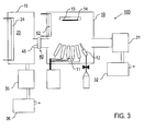
- FIG. 3 illustrates, by way of example, the further embodiment of the MBE device 100 according to the invention.
- the turbomolecular pump 31 is connected to the fore pump 32 via a vacuum connection 15 connected to the vacuum chamber 10, as it is known from conventional MBE devices.
- the vacuum chamber 10 is connected via a vacuum connection 17 with an additional vacuum chamber 15, in which at least one cooling plate 23 is arranged as a cold trap of the cold trap device 20.
- the vacuum chamber 10 and the auxiliary vacuum chamber 15 are coupled via the vacuum connection 17, in which the locking device 40 is provided.
- a vacuum-tight valve 45 is provided in the vacuum connection 17.
- the additional vacuum chamber 15 can be evacuated with a further combination of a turbomolecular pump 35 and a fore pump 36.
- one or more cold traps may be provided as a baffle between the vacuum chamber 10 and the pumping device 30 with one or more cooling shields be combined in one or more additional vacuum chambers 15.
Landscapes
- Chemical & Material Sciences (AREA)
- Engineering & Computer Science (AREA)
- Crystallography & Structural Chemistry (AREA)
- Materials Engineering (AREA)
- Metallurgy (AREA)
- Organic Chemistry (AREA)
- Chemical Kinetics & Catalysis (AREA)
- General Chemical & Material Sciences (AREA)
- Inorganic Chemistry (AREA)
- Physical Deposition Of Substances That Are Components Of Semiconductor Devices (AREA)
- Crystals, And After-Treatments Of Crystals (AREA)
Applications Claiming Priority (1)
| Application Number | Priority Date | Filing Date | Title |
|---|---|---|---|
| DE102007054851A DE102007054851A1 (de) | 2007-11-16 | 2007-11-16 | MBE-Einrichtung und Verfahren zu deren Betrieb |
Publications (2)
| Publication Number | Publication Date |
|---|---|
| EP2060662A2 true EP2060662A2 (fr) | 2009-05-20 |
| EP2060662A3 EP2060662A3 (fr) | 2010-05-19 |
Family
ID=40139198
Family Applications (1)
| Application Number | Title | Priority Date | Filing Date |
|---|---|---|---|
| EP08019625A Withdrawn EP2060662A3 (fr) | 2007-11-16 | 2008-11-10 | Dispositif MBE et son procédé de fonctionnement |
Country Status (6)
| Country | Link |
|---|---|
| US (1) | US20090137099A1 (fr) |
| EP (1) | EP2060662A3 (fr) |
| JP (1) | JP2009124156A (fr) |
| CA (1) | CA2643960A1 (fr) |
| DE (1) | DE102007054851A1 (fr) |
| TW (1) | TW200923145A (fr) |
Cited By (3)
| Publication number | Priority date | Publication date | Assignee | Title |
|---|---|---|---|---|
| EP2264225A1 (fr) * | 2009-06-18 | 2010-12-22 | Riber | Appareil d'épitaxie à faisceau moléculaire pour la production de tranches de matériau semi-conducteur |
| EP2264224A1 (fr) * | 2009-06-18 | 2010-12-22 | Riber | Appareil pour le dépôt d'une couche mince de matériau sur un substrat et procédé de régénération pour un tel appareil |
| WO2012139714A1 (fr) * | 2011-04-12 | 2012-10-18 | Createc Fischer & Co. Gmbh | Dispositif de fermeture de cellules d'évaporation pour une installation de revêtement |
Families Citing this family (15)
| Publication number | Priority date | Publication date | Assignee | Title |
|---|---|---|---|---|
| KR101010196B1 (ko) * | 2010-01-27 | 2011-01-21 | 에스엔유 프리시젼 주식회사 | 진공 증착 장비 |
| KR102052074B1 (ko) * | 2013-04-04 | 2019-12-05 | 삼성디스플레이 주식회사 | 증착 장치, 이를 이용한 박막 형성 방법 및 유기 발광 표시 장치 제조 방법 |
| CN104073777A (zh) * | 2014-04-08 | 2014-10-01 | 上海华力微电子有限公司 | 六氯乙硅烷机台及其保养维护方法 |
| CN105161573B (zh) * | 2015-09-17 | 2017-03-22 | 浙江师范大学 | 一种制造氢化纳米晶硅薄膜太阳能电池的系统和方法 |
| JP5988285B1 (ja) * | 2015-10-21 | 2016-09-07 | 株式会社島川製作所 | アンモニアを含む排ガスの処理装置および処理方法 |
| DE102017106431A1 (de) * | 2017-03-24 | 2018-09-27 | Aixtron Se | Vorrichtung und Verfahren zum Herabsetzen des Wasserpartialdrucks in einer OVPD-Beschichtungseinrichtung |
| US11519095B2 (en) * | 2019-04-22 | 2022-12-06 | Peng DU | MBE system with direct evaporation pump to cold panel |
| US11342484B2 (en) | 2020-05-11 | 2022-05-24 | Silanna UV Technologies Pte Ltd | Metal oxide semiconductor-based light emitting device |
| EP4423325A4 (fr) | 2021-10-27 | 2025-08-27 | Silanna UV Technologies Pte Ltd | Procédés et systèmes de chauffage d'un substrat à large bande interdite |
| US20230135911A1 (en) * | 2021-11-04 | 2023-05-04 | Qorvo Us, Inc. | MOLECULAR BEAM EPITAXY (MBE) REACTORS AND METHODS FOR n+GaN REGROWTH |
| EP4430674A4 (fr) | 2021-11-10 | 2025-10-01 | Silanna UV Technologies Pte Ltd | Matériaux oxydes épitaxiaux, structures et dispositifs |
| JP7814510B2 (ja) | 2021-11-10 | 2026-02-16 | シランナ・ユー・ブイ・テクノロジーズ・プライベート・リミテッド | エピタキシャル酸化物材料、構造、及びデバイス |
| JP7829033B2 (ja) | 2021-11-10 | 2026-03-12 | シランナ・ユー・ブイ・テクノロジーズ・プライベート・リミテッド | 酸化マグネシウムゲルマニウムを含む超ワイドバンドギャップ半導体デバイス |
| CN116588907B (zh) * | 2023-07-18 | 2023-10-27 | 苏州焜原光电有限公司 | 用于分子束外延腔体中的磷回收单元、系统及回收方法 |
| CN117230527A (zh) * | 2023-09-07 | 2023-12-15 | 埃特曼半导体技术有限公司 | 隔离装置及分子束外延设备 |
Citations (4)
| Publication number | Priority date | Publication date | Assignee | Title |
|---|---|---|---|---|
| JPS6130664A (ja) | 1984-07-18 | 1986-02-12 | Rohm Co Ltd | 真空装置の駆動方法 |
| EP0607435A1 (fr) | 1992-08-07 | 1994-07-27 | Asahi Kasei Kogyo Kabushiki Kaisha | Dispositif semi-conducteur a base de nitrure et fabrication |
| EP0806499A1 (fr) | 1996-05-09 | 1997-11-12 | Sharp Kabushiki Kaisha | Procédé et dispositif pour la fabrication de semi-conducteurs |
| US20050061150A1 (en) | 2003-09-24 | 2005-03-24 | Mardian Allen P. | Process byproduct trap, method of use, and system including same |
Family Cites Families (4)
| Publication number | Priority date | Publication date | Assignee | Title |
|---|---|---|---|---|
| US3294670A (en) * | 1963-10-07 | 1966-12-27 | Western Electric Co | Apparatus for processing materials in a controlled atmosphere |
| US5520002A (en) * | 1995-02-01 | 1996-05-28 | Sony Corporation | High speed pump for a processing vacuum chamber |
| US6503578B1 (en) * | 2000-05-05 | 2003-01-07 | National Science Council | Method for preparing ZnSe thin films by ion-assisted continuous wave CO2 laser deposition |
| GB2363518A (en) * | 2000-06-17 | 2001-12-19 | Sharp Kk | A method of growing a nitride layer on a GaN substrate |
-
2007
- 2007-11-16 DE DE102007054851A patent/DE102007054851A1/de not_active Ceased
-
2008
- 2008-11-10 EP EP08019625A patent/EP2060662A3/fr not_active Withdrawn
- 2008-11-13 US US12/270,420 patent/US20090137099A1/en not_active Abandoned
- 2008-11-14 TW TW097144023A patent/TW200923145A/zh unknown
- 2008-11-17 CA CA002643960A patent/CA2643960A1/fr not_active Abandoned
- 2008-11-17 JP JP2008293886A patent/JP2009124156A/ja active Pending
Patent Citations (4)
| Publication number | Priority date | Publication date | Assignee | Title |
|---|---|---|---|---|
| JPS6130664A (ja) | 1984-07-18 | 1986-02-12 | Rohm Co Ltd | 真空装置の駆動方法 |
| EP0607435A1 (fr) | 1992-08-07 | 1994-07-27 | Asahi Kasei Kogyo Kabushiki Kaisha | Dispositif semi-conducteur a base de nitrure et fabrication |
| EP0806499A1 (fr) | 1996-05-09 | 1997-11-12 | Sharp Kabushiki Kaisha | Procédé et dispositif pour la fabrication de semi-conducteurs |
| US20050061150A1 (en) | 2003-09-24 | 2005-03-24 | Mardian Allen P. | Process byproduct trap, method of use, and system including same |
Cited By (7)
| Publication number | Priority date | Publication date | Assignee | Title |
|---|---|---|---|---|
| EP2264225A1 (fr) * | 2009-06-18 | 2010-12-22 | Riber | Appareil d'épitaxie à faisceau moléculaire pour la production de tranches de matériau semi-conducteur |
| EP2264224A1 (fr) * | 2009-06-18 | 2010-12-22 | Riber | Appareil pour le dépôt d'une couche mince de matériau sur un substrat et procédé de régénération pour un tel appareil |
| WO2010146129A1 (fr) * | 2009-06-18 | 2010-12-23 | Riber | Appareil d'épitaxie par jets moléculaires permettant de fabriquer des plaquettes de matériau semi-conducteur |
| WO2010146130A1 (fr) * | 2009-06-18 | 2010-12-23 | Riber | Appareil permettant de déposer un mince film de matériau sur un substrat et procédé de régénération pour un tel appareil |
| CN102803580A (zh) * | 2009-06-18 | 2012-11-28 | 瑞必尔 | 用于制造半导体材料薄片的分子束外延装置 |
| US8858713B2 (en) | 2009-06-18 | 2014-10-14 | Riber | Apparatus for depositing a thin film of material on a substrate and regeneration process for such an apparatus |
| WO2012139714A1 (fr) * | 2011-04-12 | 2012-10-18 | Createc Fischer & Co. Gmbh | Dispositif de fermeture de cellules d'évaporation pour une installation de revêtement |
Also Published As
| Publication number | Publication date |
|---|---|
| EP2060662A3 (fr) | 2010-05-19 |
| US20090137099A1 (en) | 2009-05-28 |
| DE102007054851A1 (de) | 2009-05-20 |
| JP2009124156A (ja) | 2009-06-04 |
| CA2643960A1 (fr) | 2009-05-16 |
| TW200923145A (en) | 2009-06-01 |
Similar Documents
| Publication | Publication Date | Title |
|---|---|---|
| EP2060662A2 (fr) | Dispositif MBE et son procédé de fonctionnement | |
| DE60119119T2 (de) | Cluster-Tool mit zwei Entgasungs-/Kühlschleusenkammern | |
| DE69801291T2 (de) | Innenbeschichtung von Vakuumbehältern | |
| DE102010000447A1 (de) | Beschichtungsvorrichtung sowie Verfahren zum Betrieb einer Beschichtungsvorrichtung mit einer Schirmplatte | |
| DE4412902A1 (de) | Verfahren zur Erhöhung der Beschichtungsrate, Verfahren zur Reduzierung der Staubdichte in einem Plasmaentladungsraum und Plasmakammer | |
| EP3071725B1 (fr) | Procédé de production d'un corps composite comportant au moins une couche fonctionnelle ou de production ultérieure d'un composant électronique ou optoélectronique | |
| DE69510132T2 (de) | Vakuumkammer für Ultrahochvakuumbehandlung bei hoher Temperatur | |
| DE19536253A1 (de) | Vorrichtung zum epitaxialen Kristallaufwachsen | |
| EP0301117A1 (fr) | Dispositif de lyophilisation | |
| DE69709230T2 (de) | Verfahren und Vorrichtung zur Herstellung Halbleitern | |
| DE102018115410A1 (de) | Vakuumanordnung und Verfahren | |
| CH652804A5 (en) | Method for regenerating the low-temperature condensation surfaces of a cryopump and cryopump appliance for implementing the method | |
| DE60220170T2 (de) | Energieschonender absperrschieber | |
| DE69214845T2 (de) | Kryopumpe mit differenzleistung | |
| DE102012213095A1 (de) | Gasseparation | |
| EP2645410A1 (fr) | Dispositif de traitement de tranches de silicium | |
| WO2018172211A1 (fr) | Dispositif et procédé pour abaisser la pression partielle de h2o dans un dispositif de revêtement par dépôt en phase vapeur organique | |
| DE102025000002A1 (de) | Refrigerator und kryopumpe | |
| DE3635941C2 (fr) | ||
| DE2512235C3 (fr) | ||
| JPS58204899A (ja) | 分子線エピタキシ−装置 | |
| DE4336035A1 (de) | Verfahren zum Betrieb einer Kryopumpe sowie Vakuumpumpensystem mit Kryopumpe und Vorpumpe | |
| CN113710833B (zh) | 直接蒸发泵至冷板的分子束外延系统 | |
| DE8804218U1 (de) | Einrichtung zur Evakuierung einer Vakuumkammer | |
| US20230135911A1 (en) | MOLECULAR BEAM EPITAXY (MBE) REACTORS AND METHODS FOR n+GaN REGROWTH |
Legal Events
| Date | Code | Title | Description |
|---|---|---|---|
| PUAI | Public reference made under article 153(3) epc to a published international application that has entered the european phase |
Free format text: ORIGINAL CODE: 0009012 |
|
| AK | Designated contracting states |
Kind code of ref document: A2 Designated state(s): AT BE BG CH CY CZ DE DK EE ES FI FR GB GR HR HU IE IS IT LI LT LU LV MC MT NL NO PL PT RO SE SI SK TR |
|
| AX | Request for extension of the european patent |
Extension state: AL BA MK RS |
|
| PUAL | Search report despatched |
Free format text: ORIGINAL CODE: 0009013 |
|
| AK | Designated contracting states |
Kind code of ref document: A3 Designated state(s): AT BE BG CH CY CZ DE DK EE ES FI FR GB GR HR HU IE IS IT LI LT LU LV MC MT NL NO PL PT RO SE SI SK TR |
|
| AX | Request for extension of the european patent |
Extension state: AL BA MK RS |
|
| 17P | Request for examination filed |
Effective date: 20101119 |
|
| AKX | Designation fees paid |
Designated state(s): AT BE BG CH CY CZ DE DK EE ES FI FR GB GR HR HU IE IS IT LI LT LU LV MC MT NL NO PL PT RO SE SI SK TR |
|
| 17Q | First examination report despatched |
Effective date: 20110822 |
|
| STAA | Information on the status of an ep patent application or granted ep patent |
Free format text: STATUS: THE APPLICATION IS DEEMED TO BE WITHDRAWN |
|
| 18D | Application deemed to be withdrawn |
Effective date: 20120103 |