EP2062780B1 - Système de store - Google Patents
Système de store Download PDFInfo
- Publication number
- EP2062780B1 EP2062780B1 EP20080018456 EP08018456A EP2062780B1 EP 2062780 B1 EP2062780 B1 EP 2062780B1 EP 20080018456 EP20080018456 EP 20080018456 EP 08018456 A EP08018456 A EP 08018456A EP 2062780 B1 EP2062780 B1 EP 2062780B1
- Authority
- EP
- European Patent Office
- Prior art keywords
- roller blind
- guide rail
- vehicle
- shaft
- sheet
- Prior art date
- Legal status (The legal status is an assumption and is not a legal conclusion. Google has not performed a legal analysis and makes no representation as to the accuracy of the status listed.)
- Not-in-force
Links
- 238000003780 insertion Methods 0.000 claims description 4
- 230000037431 insertion Effects 0.000 claims description 4
- 239000004753 textile Substances 0.000 claims 1
- 239000004744 fabric Substances 0.000 description 15
- 230000008878 coupling Effects 0.000 description 5
- 238000010168 coupling process Methods 0.000 description 5
- 238000005859 coupling reaction Methods 0.000 description 5
- 230000000694 effects Effects 0.000 description 3
- 238000004804 winding Methods 0.000 description 3
- 238000011161 development Methods 0.000 description 2
- 230000018109 developmental process Effects 0.000 description 2
- 230000005540 biological transmission Effects 0.000 description 1
- 230000007423 decrease Effects 0.000 description 1
- 238000004519 manufacturing process Methods 0.000 description 1
- 230000009467 reduction Effects 0.000 description 1
- 238000007665 sagging Methods 0.000 description 1
- 238000000926 separation method Methods 0.000 description 1
- 230000007704 transition Effects 0.000 description 1
Images




Classifications
-
- B—PERFORMING OPERATIONS; TRANSPORTING
- B60—VEHICLES IN GENERAL
- B60R—VEHICLES, VEHICLE FITTINGS, OR VEHICLE PARTS, NOT OTHERWISE PROVIDED FOR
- B60R5/00—Compartments within vehicle body primarily intended or sufficiently spacious for trunks, suit-cases, or the like
- B60R5/04—Compartments within vehicle body primarily intended or sufficiently spacious for trunks, suit-cases, or the like arranged at rear of vehicle
- B60R5/044—Compartments within vehicle body primarily intended or sufficiently spacious for trunks, suit-cases, or the like arranged at rear of vehicle luggage covering means, e.g. parcel shelves
- B60R5/045—Compartments within vehicle body primarily intended or sufficiently spacious for trunks, suit-cases, or the like arranged at rear of vehicle luggage covering means, e.g. parcel shelves collapsible or transformable
- B60R5/047—Compartments within vehicle body primarily intended or sufficiently spacious for trunks, suit-cases, or the like arranged at rear of vehicle luggage covering means, e.g. parcel shelves collapsible or transformable collapsible by rolling-up
Definitions
- the invention relates to a roller blind system for a vehicle, in particular for covering a rear stowage space of the vehicle, with a rotatably mounted roller blind shaft, a wound on the roller blind and unwindable in a unwinding flexible sheet and a receiving device for fixing a blind shaft remote from the distal end of the flexible sheet in an at least partially completed state.
- Generic shade systems are known from the prior art. They are used, in particular, as cargo compartment covers, which prevent the possibility of being viewed from outside the vehicle in the luggage area of the vehicle. Other fields of application are the use as a separation net or sun visor.
- the fabric is rolled up by means of a spring means becomes.
- This spring means is usually in the form of a coil spring, which exerts a remindholomoment on the roller shaft.
- the stripped sheet is thereby subjected to a return force which retracts the sheet into the wound up state.
- it is secured in a functional state by fixing a distal end of the sheet by means of receiving devices provided therefor.
- the object of the invention is therefore to develop a generic shade system for a vehicle to the effect that with a low cost, a reliable electromotive control of the fabric is made possible.
- the roller blind shaft is directly driven by the electric motor.
- the electric motor can be controlled directly by means of dedicated switches, for example in the boot area.
- the engine is controlled by a control unit, which automatically takes over the control of the electric motor based on further data, such as the opening state of a tailgate.
- an electric motor is used, which has a cogging torque in the absence of energization, which prevents the unwound and secured by the receiving device sags.
- the roller shaft is preferably arranged in a cassette housing, wherein the electric motor can be provided inside or outside of this cassette housing.
- the receiving device has at least one movable stop, which is acted upon by a spring force of a spring means in the direction of the unwinding direction.
- a spring force of a spring means By this spring force, the flexible fabric is pulled in the direction of its unwound state. The effect is that the fabric is stretched and sagging is prevented.
- the tensioned state is maintained by the spring means and the stop which is moved in correspondence with the sheet. If by the electric motor, the sheet or a part thereof is wound on the roller shaft, so the spring means is further deflected due to the movement of the stop and thereby additionally stretched.
- the spring force of the spring means is so dimensioned that it is always lower than the motor motor applied by the electric motor, so that the engine power of the electric motor can always overcome the opposite spring force.
- the spring force is sufficiently large to hold the sheet in a visually properly tensioned state.
- any device is considered, which interacts with the distal end of the sheet or a fixedly assigned portion such that it is deflected by the electromotive winding of the sheet under increasing the tension of the spring means.
- the receiving device has at least one guide rail.
- the guide rail is provided in a possible embodiment for directly receiving an extension at the distal end of the flexible sheet.
- the distal end of the flexible sheet or a projection provided thereon can be secured to a guide carriage, which in turn is mounted in the guide rail and is guided by it.
- the guide rail also serves to receive the movable stop.
- the guide rail may be formed as a groove, in which engages an extension of the flexible sheet and / or in which the stop is movably guided.
- a particularly simple embodiment provides that the guide rail extends in alignment with the roller blind shaft.
- the guide rail is preferably designed with respect to its length such that the flexible sheet can always remain within the guide rail. Their length corresponds to at least the distance by which the distal end of the sheet is movable between a wound-up state and a state of unwound state. The distal end of the fabric is thus guided through the guide rail both in the compact storage state and in the unwound functional state.
- the guide rail is at least partially not aligned with the roller shaft. This makes it possible to realize comfort functions, such as in the case of a luggage compartment cover, a condition with raised distal end of the fabric to allow easy access to the underlying luggage.
- the guide rail is therefore preferably arranged in a vehicle column terminating the vehicle at the rear, in particular a C-pillar or a D-pillar. In such an embodiment, it is also considered advantageous if the rail is not provided for receiving the flexible sheet in its storage condition.
- the guide rail is preferably completely spaced from the roller blind, so that the intended operation provides that the fabric is first subtracted from the roller shaft or unwound by the electric motor and only then used in the guide rail.
- the movable stop is provided in the region of the guide rail, so that the distal end of the flexible sheet is subjected to force only by this stop when it is inserted into the guide rail.
- the distal end of the sheet can thus be handled independently of the stop, until it is in the guide rail or provided thereon Carriage is used. Only then does the spring-loaded stop unfold its effect.
- At least one further fixing means is preferably provided on the guide rail, preferably a deflectable holding pawl.
- This additional fixing means makes it possible to additionally secure the distal end of the flexible sheet in a defined functional state.
- the guide rail extends in the D-pillar of a combined vehicle and similar application fields where load compartment covers with a comfort feature described above application, such additional backup may preferably be provided in a horizontal position of the fabric.
- a spring motor is used, wherein the spring force is transmitted by the spring motor by means of a cable to the movable stop.
- the cable allows a particularly flexible arrangement of the spring motor.
- the stop is slidably provided in a groove of the guide rail, wherein it is considered to be particularly advantageous if this groove in its groove bottom has a groove following the opening, by means of which the stop out and / or can be connected to the cable.
- the cable can also be guided in the groove itself.
- the receiving device with the guide rail, the movable stop and the spring means is designed as a pre-assembly unit.
- the receiving device is considered when said components can first be interconnected before being assembled in their entirety in the vehicle.
- Such a preassembly unit is desired in view of a simple and fast vehicle production.
- the attachment of the pre-assembly on the vehicle is preferably carried out by a determination of the guide rail or a determination of the guide rail connected to the mounting portions on the vehicle. It is particularly preferred if a chassis accommodating the various components is provided, in which the guide rail is preferably provided in one piece.
- the roller blind shaft is removable without tools from a vehicle-fixed roller blind receptacle and can be used in this vehicle-mounted roller blind receptacle, wherein the electric motor is fixed to the vehicle.
- This design makes it possible to remove and insert the roller blind shaft without the need for electrical connection.
- the roller shaft which is preferably mounted in a detachable with the roller shaft cassette housing, is simultaneously separated mechanically from the electric motor of the drive when removing from the roller blind. This remains firmly mounted in the vehicle. He is preferably provided directly on or in the Rollowellenfact.
- the design of the roller blind as a tool-free removable roller shaft increases the flexibility of the vehicle, since the removal can be gained space. As Rollowellenability in the sense of this development, a recording of a cassette housing is considered, within which the roller blind shaft is mounted.
- a positive-acting coupling is preferably provided between the electric motor and a drive shaft of the roller shaft, which may also be identical to the roller shaft.
- This coupling can be axially coupled, for example, so that it is provided after the onset of the roller shaft, these first to move axially to the Form fit.
- this clutch comprises two meshing with each other in the inserted state of the roller blind gears, one of which is provided directly or indirectly on the electric motor and the other is provided on the drive shaft of the roller blind.
- the rollowellen workede gear is preferably provided directly on the roller shaft.
- the roller blind itself preferably has a radial receiving slot for insertion of the flexible sheet. Due to the fact that no coil spring or the like is required within the roller shaft, a very thin design of the roller blind shaft can be provided.
- the determination of the sheet to the roller shaft can be realized in the simplest case by the radial receiving slot through which the sheet is pushed before it is then wound up on the roller shaft.
- FIG. 1 shows the rear of a vehicle with a roller blind system according to the invention.
- the roller blind system has as essential components a vehicle-mounted cassette housing 10, within which a roller shaft 20 is rotatably mounted. On the roller shaft 20, a flexible sheet 30 is wound, which in the representation of FIG. 1 is shown in the developed state.
- an electric motor 12 is provided within the cassette housing 10, which is rotationally coupled by means of a gear, not shown, with the roller shaft 20 and so on Unwinding of the flexible sheet 30 of the roller shaft 20 and a winding of the flexible sheet 30 on the roller shaft 20 allowed.
- a guide rod 32 is provided, which extends over the entire width of the sheet 30 and extends beyond the sheet 30 in projections 32 a on the outside.
- the guide rails 40 are formed as a double profile. At a relative to the vehicle interior provided on the inside rectangular rectangular cross-section 42a is followed by a taper 42b and an outside approximately in a circular free cross section 42c.
- a carriage 50 is inserted, which has a receiving portion 52 and a cable pull 54 connected thereto.
- the receiving portion 52 is disposed in the inserted state of the carriage 50 in the rectangular cross-sectional portion 42 a, while the cable pull 54 is arranged in the circular cross-sectional portion 42 c.
- the receiving portion At the front end in the vehicle longitudinal direction, the receiving portion has a stop surface 52a.
- a cable 60 is connected to the carriage 50, the meaning of which below in connection with the FIG. 3 is explained.
- FIG. 3 shows in a schematic manner how the guide rail 40 and the carriage 50 are connected by means of the cable 60 with a spring motor 62.
- the cable 60 extends from the carriage 50 in the direction of extension of the guide rail 40 in the direction of the vehicle rear, is deflected there by means of a guide roller 64 and then flows in spring motor 62 shown only schematically.
- This spring motor 62 provides a force application of the carriage 50 in the direction of the second
- FIG. 1 leads the illustrated and described design to the possibility by means of the electric motor 12, the sheet 30 in an in FIG. 1 to be able to move in a high-traffic position shown in dashed lines.
- a part of the sheet 30 is wound by the electric motor 12 on the roller shaft 20, resulting in a reduction of the unwound portion of the sheet 30.
- the distal end 30a of the sheet 30 in the guide rail 40 is pulled up. This is done against the spring force of the spring motor 62 by the application of force to the carriage 50 in the direction 2 and by means of the stop 52 a care that the sheet does not sag even in this state shown in dashed lines.
- roller blind system shown is characterized in particular by the fact that the electric motor is provided on the roller shaft 30, where sufficient space is available. In the rear area of the vehicle to the receiving devices with the guide rails 40, however, only the structurally very inexpensive spring motor 62 is required.
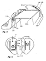
- FIG. 4 shows a second embodiment of a roller blind system according to the invention.
- This in turn is arranged in the rear region of a vehicle and in turn has a cassette housing 110 in which a roller shaft 120 is rotatably mounted in a manner not shown in detail.
- a sheet 130 is wound, which in Fig. 4 in the vehicle longitudinal direction to the rear of the roller shaft 120 is unwound.
- a support rod 132 is provided which extends laterally with extensions 132a over the sheet.
- Guide rails 140 are provided on the D pillars 148 of the vehicle.
- the cassette housing 110 is removable.
- vehicle-mounted seats 114 are provided on both sides of the cassette housing.
- the cartridge housing 110 can be inserted from above.
- a motor 112 for driving the roller shaft 120 is accommodated in the left-side receptacle 114 instead of the cartridge case 110.
- FIG. 5 shows the coupling portion between this left-side receiving device 114 and the cassette housing 110.
- the receiving device 114 shown on the left contains the electric motor 112, the output shaft 112a of which is led out towards the center of the vehicle out of the housing of the receiving device 114 and is provided there with a toothed wheel 112b.
- an approximately U-shaped web 118 is provided on this side of the receiving device 114.
- front end of the cassette housing 110 also webs 110a provided between which also a gear 111 is arranged.
- This gear 111 is rotatably connected by means of a shaft 111 a with the roller shaft 120 within the cassette housing 110.
- the cassette housing 110 can be inserted in the direction of the arrow 4 from above into the space defined by the U-shaped web 118 of the receiving device 114, wherein the two gears 111, 112b engage with each other.
- torque may be transmitted from the motor 112 within the receptacle 114 to the roller shaft 120 within the cartridge housing 110.
- the guide rail 140 is, as in the FIGS. 6a, 6b and 7 is formed as part of an integral assembly 190.
- This has a plastic housing 192, in which the groove 140 is integrally provided.
- the groove 140 transitions into an insertion region 140c, into which the extension 132a of the end-side support rod 132 of the fabric 130 can be inserted.
- a carriage 150 is arranged in the groove 140. Deviating from the embodiment of FIGS. 1 to 3 However, this carriage 150 to limit the mobility of the extensions 132, only one stop surface 152a.
- the abutment surface 150a is integrally connected to a cable pull holder 154.
- a cable pull 160 attached to the cable puller 154 is like the rear view of the FIG. 6b shows, connected to a spring motor 162, which is provided directly on the assembly 190.
- an additional retaining pawl 180 is provided at the lower end 140b of the groove 140. This holding pawl is acted upon by a force provided on the rear side spring 182. As a result, an additional securing of the extensions 132a in the lower end position can be achieved.
Landscapes
- Engineering & Computer Science (AREA)
- Mechanical Engineering (AREA)
- Operating, Guiding And Securing Of Roll- Type Closing Members (AREA)
Claims (8)
- Système de store pour un véhicule, en particulier pour recouvrir un coffre arrière du véhicule, avec- un arbre d'enroulement (20 ; 120) logé de manière orientable dans un véhicule,- une structure plane souple (30 ; 130) enroulée sur l'arbre d'enroulement (20 ; 120) et pouvant être déroulée dans une direction de déroulement, et- un dispositif récepteur (40 ; 140, 190) permettant de maintenir une extrémité distale (30a; 130a), opposée à l'arbre d'enroulement (20 ; 120), de la structure plane textile (30 ; 130) dans un état au moins en partie déroulé,
sachant- qu'est prévu un moteur électrique (12 ; 112) pour entraîner l'arbre d'enroulement (20; 120),caractérisé en ce que
le dispositif récepteur (40 ; 140, 190) présente au moins une butée mobile (52a ; 152a) qui est soumise à un effort par une force de ressort d'un entraînement par ressort (62 ; 162) et au moyen d'un câble (60 ; 160) en direction du sens de déroulement. - Système de store selon la revendication 1,
caractérisé en ce que
le dispositif récepteur (40 ; 140, 190) présente au moins un rail de guidage (40; 140). - Système de store selon la revendication 2,
caractérisé en ce que
le rail de guidage s'étend de manière alignée par rapport à l'arbre d'entraînement. - Système de store selon la revendication 2,
caractérisé en ce que
le rail de guidage (40 ; 140) s'étend au moins en partie en déport par rapport à l'arbre d'enroulement (30; 130). - Système de store selon l'une des revendications 2 à 4,
caractérisé en ce que
le rail de guidage (40 ; 140) est conçu sous forme de rainure de guidage (40; 140), sachant que la butée mobile (52a ; 152a) est disposée à l'intérieur de la rainure de guidage. - Système de store selon l'une des revendications 2 à 5,
caractérisé en ce que
est prévu sur le rail de guidage (140) au moins un moyen de réception (180) supplémentaire, de préférence un loquet de maintien (180) pouvant être dévié. - Système de store selon l'une des revendications 2 à 6,
caractérisé en ce que
le dispositif récepteur (190) avec le rail de guidage (140), la butée mobile (152a) ainsi que l'entraînement par ressort (162) est conçu comme une unité de prémontage (190). - Système de store selon l'une des revendications précédentes,
caractérisé en ce que
le système de store (130) présente une fente de réception radiale pour insérer la structure plane souple.
Applications Claiming Priority (1)
| Application Number | Priority Date | Filing Date | Title |
|---|---|---|---|
| DE102007057074A DE102007057074A1 (de) | 2007-11-23 | 2007-11-23 | Rollosystem |
Publications (2)
| Publication Number | Publication Date |
|---|---|
| EP2062780A1 EP2062780A1 (fr) | 2009-05-27 |
| EP2062780B1 true EP2062780B1 (fr) | 2010-06-02 |
Family
ID=40280774
Family Applications (1)
| Application Number | Title | Priority Date | Filing Date |
|---|---|---|---|
| EP20080018456 Not-in-force EP2062780B1 (fr) | 2007-11-23 | 2008-10-22 | Système de store |
Country Status (3)
| Country | Link |
|---|---|
| EP (1) | EP2062780B1 (fr) |
| CN (1) | CN101439693B (fr) |
| DE (2) | DE102007057074A1 (fr) |
Families Citing this family (13)
| Publication number | Priority date | Publication date | Assignee | Title |
|---|---|---|---|---|
| DE102010020657B4 (de) | 2010-05-05 | 2015-01-08 | Bos Gmbh & Co. Kg | Rollosystem für einen Fahrzeuginnenraum |
| DE102010052743B4 (de) * | 2010-11-26 | 2016-10-27 | Audi Ag | Kraftfahrzeug mit werkzeuglos entnehmbarem Bauteil sowie Hutablage für ein Kraftfahrzeug |
| JP2012206675A (ja) | 2011-03-30 | 2012-10-25 | Tokai Rika Co Ltd | トノカバー装置 |
| DE102012202293A1 (de) * | 2012-02-15 | 2013-08-22 | Brose Fahrzeugteile Gmbh & Co. Kommanditgesellschaft, Coburg | Verstelleinrichtung für eine Laderaumabdeckung |
| EP2958773B2 (fr) * | 2013-02-21 | 2021-02-24 | Toyota Jidosha Kabushiki Kaisha | Dispositif de couvre-habitacle et système destiné à un véhicule |
| DE102013017104A1 (de) * | 2013-10-15 | 2015-04-30 | GM Global Technology Operations, LLC (n.d. Ges. d. Staates Delaware) | Kofferraumabdeckung und Fahrzeug mit der Kofferraumabdeckung |
| DE102015118305B4 (de) * | 2015-10-01 | 2025-07-24 | Fkt Gmbh | Abtrennvorrichtung für einen Laderaum eines Kraftfahrzeugs |
| DE102016215599B3 (de) * | 2016-08-19 | 2017-07-27 | Bos Gmbh & Co. Kg | Schutzvorrichtung für einen Fahrzeuginnenraum |
| CN108146352B (zh) * | 2017-12-26 | 2021-04-23 | 重庆程顺汽车配件制造有限公司 | 一种用于汽车后备箱固定装置 |
| FR3096631B1 (fr) * | 2019-05-31 | 2021-11-12 | Inteva Products France Sas | Cache-bagages motorisé pour vehicule |
| CZ310349B6 (cs) * | 2023-03-06 | 2025-03-26 | ŠKODA AUTO a.s. | Sestava pro zakrývání zavazadlového prostoru |
| CZ310357B6 (cs) * | 2023-10-16 | 2025-04-02 | ŠKODA AUTO a.s. | Sestava pro zakrývání zavazadlového prostoru |
| CN117601770A (zh) * | 2024-01-24 | 2024-02-27 | 宁波帅特龙集团有限公司 | 一种车用电动遮物帘 |
Family Cites Families (5)
| Publication number | Priority date | Publication date | Assignee | Title |
|---|---|---|---|---|
| EP0866208A3 (fr) * | 1997-03-20 | 2001-02-14 | Robert Goyvaerts | Volet roulant |
| US6086133A (en) * | 1998-04-06 | 2000-07-11 | Alonso; Miguel | Vehicle window shade arrangement |
| DE19944948C1 (de) * | 1999-09-20 | 2001-05-31 | Baumeister & Ostler Gmbh Co | Schutzvorrichtung für einen Innenraum eines Kraftfahrzeuges |
| DE10229675B4 (de) * | 2002-06-27 | 2005-06-09 | Bos Gmbh & Co. Kg | Verriegelungseinrichtung für ein Kraftfahrzeug |
| DE10330627B4 (de) * | 2003-07-07 | 2006-08-03 | Bos Gmbh & Co. Kg | Laderaumabdeckung mit selbstlaufendem Auszugsprofil |
-
2007
- 2007-11-23 DE DE102007057074A patent/DE102007057074A1/de not_active Withdrawn
-
2008
- 2008-10-22 DE DE200850000740 patent/DE502008000740D1/de active Active
- 2008-10-22 EP EP20080018456 patent/EP2062780B1/fr not_active Not-in-force
- 2008-11-24 CN CN 200810182164 patent/CN101439693B/zh not_active Expired - Fee Related
Also Published As
| Publication number | Publication date |
|---|---|
| CN101439693B (zh) | 2013-02-06 |
| EP2062780A1 (fr) | 2009-05-27 |
| DE502008000740D1 (de) | 2010-07-15 |
| DE102007057074A1 (de) | 2009-06-04 |
| CN101439693A (zh) | 2009-05-27 |
Similar Documents
| Publication | Publication Date | Title |
|---|---|---|
| EP2062780B1 (fr) | Système de store | |
| EP1666291B1 (fr) | Store à enrouler de fenêtre avec montage simplifié | |
| EP1389544B1 (fr) | Store à enrouleur avec un méchanisme d' accouplement | |
| DE102004046783A1 (de) | Rolloanordnung für ein Kraftfahrzeug | |
| DE102013110650A1 (de) | Anordnung für ein Rollo | |
| EP1967401A2 (fr) | Store de fenêtre latérale actionné de manière automatique | |
| DE102007012259A1 (de) | Sonnenschutzrollo für Kraftfahrzeuge | |
| EP1740426B1 (fr) | Systeme de store pour toit de vehicule | |
| EP1418073A1 (fr) | Store à enrouler avec couvercle sur la fente extracte | |
| DE102011113207B4 (de) | Fahrzeugrolloanordnung und Fahrzeugdach | |
| DE19834777C2 (de) | Rollo, insbesondere Sonnenschutzrollo für die transparente Dachscheibe eines Kraftfahrzeugs | |
| DE19750715C1 (de) | Rollovorrichtung für ein Fahrzeugdach mit transparenter Dachscheibe | |
| DE102007057073B4 (de) | Abdecksystem für ein Fahrzeug | |
| WO2008014743A1 (fr) | Dispositif de store pour un toit de véhicule | |
| DE102004038756A1 (de) | Sonnenschutzrollo für Glasdächer | |
| EP1747923A2 (fr) | Store à enrouler de fenêtre avec des pousées non-profilées | |
| DE102008063775A1 (de) | Fahrzeugfensterrollo | |
| DE10215678B4 (de) | Beschattungseinrichtung für eine Scheibe | |
| DE202007018359U1 (de) | Rollosystem | |
| DE102006028353A1 (de) | Fensterrollo für ein Fahrzeugfenster | |
| EP0529591B1 (fr) | Dispositif de store, de préference pour lunettes arrières de véhicules | |
| DE202007012981U1 (de) | Verstelleinrichtung für eine Abdeckvorrichtung in einem Kraftfahrzeug | |
| DE102010018437A1 (de) | Wickelvorrichtung für eine Rolloanordnung, Rolloanordnung und Dachanordnung | |
| DE10324545B4 (de) | Wickelwelle mit externem Federantrieb | |
| DE202005011290U1 (de) | Rollovorrichtung für ein Fahrzeug |
Legal Events
| Date | Code | Title | Description |
|---|---|---|---|
| PUAI | Public reference made under article 153(3) epc to a published international application that has entered the european phase |
Free format text: ORIGINAL CODE: 0009012 |
|
| AK | Designated contracting states |
Kind code of ref document: A1 Designated state(s): AT BE BG CH CY CZ DE DK EE ES FI FR GB GR HR HU IE IS IT LI LT LU LV MC MT NL NO PL PT RO SE SI SK TR |
|
| AX | Request for extension of the european patent |
Extension state: AL BA MK RS |
|
| 17P | Request for examination filed |
Effective date: 20090701 |
|
| 17Q | First examination report despatched |
Effective date: 20090730 |
|
| GRAP | Despatch of communication of intention to grant a patent |
Free format text: ORIGINAL CODE: EPIDOSNIGR1 |
|
| AKX | Designation fees paid |
Designated state(s): DE FR SE |
|
| GRAS | Grant fee paid |
Free format text: ORIGINAL CODE: EPIDOSNIGR3 |
|
| GRAA | (expected) grant |
Free format text: ORIGINAL CODE: 0009210 |
|
| AK | Designated contracting states |
Kind code of ref document: B1 Designated state(s): DE FR SE |
|
| REF | Corresponds to: |
Ref document number: 502008000740 Country of ref document: DE Date of ref document: 20100715 Kind code of ref document: P |
|
| PG25 | Lapsed in a contracting state [announced via postgrant information from national office to epo] |
Ref country code: SE Free format text: LAPSE BECAUSE OF FAILURE TO SUBMIT A TRANSLATION OF THE DESCRIPTION OR TO PAY THE FEE WITHIN THE PRESCRIBED TIME-LIMIT Effective date: 20100602 |
|
| PLBE | No opposition filed within time limit |
Free format text: ORIGINAL CODE: 0009261 |
|
| STAA | Information on the status of an ep patent application or granted ep patent |
Free format text: STATUS: NO OPPOSITION FILED WITHIN TIME LIMIT |
|
| 26N | No opposition filed |
Effective date: 20110303 |
|
| REG | Reference to a national code |
Ref country code: DE Ref legal event code: R097 Ref document number: 502008000740 Country of ref document: DE Effective date: 20110302 |
|
| PGFP | Annual fee paid to national office [announced via postgrant information from national office to epo] |
Ref country code: FR Payment date: 20121113 Year of fee payment: 5 |
|
| REG | Reference to a national code |
Ref country code: FR Ref legal event code: ST Effective date: 20140630 |
|
| PG25 | Lapsed in a contracting state [announced via postgrant information from national office to epo] |
Ref country code: FR Free format text: LAPSE BECAUSE OF NON-PAYMENT OF DUE FEES Effective date: 20131031 |
|
| PGFP | Annual fee paid to national office [announced via postgrant information from national office to epo] |
Ref country code: DE Payment date: 20161026 Year of fee payment: 9 |
|
| REG | Reference to a national code |
Ref country code: DE Ref legal event code: R119 Ref document number: 502008000740 Country of ref document: DE |
|
| PG25 | Lapsed in a contracting state [announced via postgrant information from national office to epo] |
Ref country code: DE Free format text: LAPSE BECAUSE OF NON-PAYMENT OF DUE FEES Effective date: 20180501 |