EP2065012B1 - Procédé et système de fabrication de restaurations dentaires en céramique - Google Patents
Procédé et système de fabrication de restaurations dentaires en céramique Download PDFInfo
- Publication number
- EP2065012B1 EP2065012B1 EP07023059A EP07023059A EP2065012B1 EP 2065012 B1 EP2065012 B1 EP 2065012B1 EP 07023059 A EP07023059 A EP 07023059A EP 07023059 A EP07023059 A EP 07023059A EP 2065012 B1 EP2065012 B1 EP 2065012B1
- Authority
- EP
- European Patent Office
- Prior art keywords
- moulding
- volume region
- press
- volume
- mould
- Prior art date
- Legal status (The legal status is an assumption and is not a legal conclusion. Google has not performed a legal analysis and makes no representation as to the accuracy of the status listed.)
- Active
Links
Images


Classifications
-
- A—HUMAN NECESSITIES
- A61—MEDICAL OR VETERINARY SCIENCE; HYGIENE
- A61C—DENTISTRY; APPARATUS OR METHODS FOR ORAL OR DENTAL HYGIENE
- A61C13/00—Dental prostheses; Making same
- A61C13/0003—Making bridge-work, inlays, implants or the like
- A61C13/0022—Blanks or green, unfinished dental restoration parts
-
- A—HUMAN NECESSITIES
- A61—MEDICAL OR VETERINARY SCIENCE; HYGIENE
- A61C—DENTISTRY; APPARATUS OR METHODS FOR ORAL OR DENTAL HYGIENE
- A61C13/00—Dental prostheses; Making same
- A61C13/08—Artificial teeth; Making same
- A61C13/082—Cosmetic aspects, e.g. inlays; Determination of the colour
-
- A—HUMAN NECESSITIES
- A61—MEDICAL OR VETERINARY SCIENCE; HYGIENE
- A61C—DENTISTRY; APPARATUS OR METHODS FOR ORAL OR DENTAL HYGIENE
- A61C13/00—Dental prostheses; Making same
- A61C13/20—Methods or devices for soldering, casting, moulding or melting
- A61C13/206—Injection moulding
Definitions
- the present invention relates to a method and system for making ceramic dental restorations to provide naturally-acting color and opacity gradients.
- a model of a dental restoration made of a completely ausbrennbaren material is attached to a later casting channel forming strand within a press muffle and the press muffle filled with an embedding, so that the model is completely surrounded by the embedding.
- the investment is cured to a refractory mold and the model is burned out to create the mold cavity corresponding to a dental restoration in the cured mold.
- a ceramic material is then pressed into the mold under pressure through the casting channel to fill the mold cavity corresponding to the dental restoration and thus to produce the dental restoration from the ceramic material.
- a disadvantage of the known methods and systems is that the known press-fit methods are only suitable for single-color dental restorations. If one wishes to faithfully mimic the gradients of color and opacity which can be present in great variety in a natural tooth in the dental restoration, subsequent surface treatment such as, for example, painting or coating is indispensable according to the prior art. Such a Subsequent surface treatment is cumbersome and expensive because of the associated manual work.
- document DE 19 714 178 discloses a method according to the preamble of claim 1.
- a method of producing dental ceramic restorations to provide natural color and opacity gradients wherein a ceramic body is completely or partially inserted through a channel system in a mold into a mold cavity corresponding to a dental restoration the mold is pressed, characterized; in that the shaped body has a first volume area and a second volume area, wherein the second volume area differs from the first volume area by a different color or opacity, and the channel system in the press molds the shaped body during pressing into the mold cavity such that material of the first volume area the mold cavity is reached in time rather than material of the second volume region and / or more material of the first volume region is pressed into the mold cavity as a material of the second volume range.
- a system for making ceramic dental restorations to provide natural-looking color and opacity gradients comprising a shaped body Ceramic or plastic, a press muffle base and an abutment system of completely burn-out material, wherein the abutment system serves to attach a model of a dental restoration made of completely burn-out material to the press muffle base, so that by means of the abutment system attached to the press muffle base model with a mold a mold system corresponding to the tapping system and a mold cavity corresponding to the model, and a mold thus produced is suitable for pressing the molded body into the mold cavity of the mold, characterized in that the mold body has a first volume region and a second volume region second volume range differs from the first volume range by a different color or opacity, and the tapping system is prefabricated and configured such that the channel system resulting from generation of the die has two Flow paths, wherein the second flow path has a larger volume than the first flow path, and where
- a ceramic body for making ceramic dental restorations to provide naturally-acting color and opacity gradients having a first volume area and a second volume area, the second volume area passing through distinguishes a different color or opacity from the first volume region, characterized in that the shaped body is pressed by a channel system in a mold completely or partially in a mold cavity corresponding to a dental restoration in the mold, and the channel system in the mold, the molding in the Pressing into the mold cavity directs that material of the first volume region reaches the mold cavity in time rather than material of the second volume region and / or more material of the first volume region is pressed into the mold cavity than material of the second volume region.
- the term "dental restoration” in this specification includes crowns, partial crowns, veneers, bridges, abutments or other dental prostheses.
- the present invention is also suitable for overmolding ceramic, metal or metal alloy frameworks.
- the term "flow path" as used herein means the path followed by a flow front of material of a volume range of the molded article as it is being pressed.
- the volume of a flow path is determined by the area traversed along the flow path by the flow front of material of a volume area times the length of the flow path.
- the flow path may split according to the design of the channel system and form branches that do not lead into the mold cavity. Flow paths of different volume ranges do not have to run through separate channels in the channel system, but can also run through a common channel.
- the total volume of a flow path is determined by the volume of the channel system which is occupied after being pressed in by a material of a volume region of the shaped body.
- the invention also encompasses methods, systems, and uses for simultaneously or non-simultaneously producing any number of dental restorations having the same or different color and opacity gradients using one or more channel systems.
- the channel system and the mold cavity corresponding to a dental restoration are completely replaced by means of a burnable material such as Plexiglas or wax prefabricated tapping system is created by a model of a dental restoration made of fully burnable material is attached via the Anungsystem to a Pressmuffelbasis a press muffle before pressing.
- the press muffle is then filled with an embedding compound so that the model and the abutment system are completely surrounded by the investment material.
- the investment is cured to a refractory mold, and the model and abutment system are burned out to create the mold cavity corresponding to a dental restoration and the channel system in the cured mold.
- the model of a dental restoration is connected mesially or distally to the abutment system. This has the advantage over an occlusal instigation of the model that the later separation of the channel system is simpler and the geometry of the opposing teeth need not be considered.
- the shaped body has a first volume area and a second volume area, wherein the second volume area differs from the first volume area by a different color or opacity.
- the various volume ranges may be a dentin mass and a dental restoration cutting edge.
- a third volume range is used that corresponds to a cervical dentin mass.
- the number of volume ranges is in principle unlimited.
- the material of the molding ie the ceramic or the Plastic, viscous or flowable and can be pressed into a mold cavity corresponding to a dental restoration in the mold.
- the channel system in the mold passes during pressing the shaped body in the mold cavity.
- the molded body which is flowable during pressing in is guided into a mold cavity corresponding to a dental restoration such that the first volume region of the molded body reaches the mold cavity in time before the second volume region.
- the shaped body made of ceramic denotes a press blank, which may be formed in one piece or in several parts.
- the individual parts are melted together before the actual press-fitting process, by heating or pressing together.
- each individual part preferably represents a volume area with a specific color and / or opacity.
- the gradient of color or opacity between the two volume regions of the shaped body is continuous and gradual, as it corresponds to the color gradients in a natural tooth.
- the molded body preferably has a press-in direction, along which the cross-sectional shape of the molded body is constant, so that the molded body along the press-in in the Press mold can be pressed.
- the shape of the shaped body may in particular be substantially cylindrical.
- the volume areas with different color or opacity gradients are distributed in the shaped body.
- the volume regions can extend essentially along the press-in direction and essentially adjoin one another at a plane with a normal, which runs essentially perpendicular to the pressing-in direction of the shaped body.
- the volume areas can essentially each constitute one layer of the shaped body and essentially adjoin one another at a plane with a normal, which runs essentially parallel to the pressing-in direction of the shaped body.
- the volume areas each make up a piece of the molded body and are adjacent to each other substantially at a level with a normal, which runs obliquely to the pressing-in direction of the molded body.
- the shaped body not only has a first and a second volume area, but at least one further volume area, which differs by a different color or opacity from an adjacent volume area.
- the channel system in the press mold must be adapted to the shaped body. This is advantageously ensured by a prefabricated Anxsystem that fits to a particular molding.
- the channel system must ensure that one volume region of the molded body reaches the mold cavity ahead of the other volume region. This can be achieved, for example, by a channel system having two flow paths, the second flow path has a larger volume than the first flow path, and wherein, during pressing, the first volume region is forced into the mold cavity through the first flow path and the second volume region is pressed into the mold cavity through the second flow path.
- the flow paths can be partially separate channels, but they do not have to be.
- Both flow paths can pass through a common channel, whereby the channel system ensures that when pressed in, a volume area of the shaped body fills a larger volume of the channel system than the other volume area. Since uniform pressure prevails during injection into the entire channel system, ie also along both flow paths, that volume region which fills a larger volume in the channel system reaches the mold cavity later than the one which fills a smaller volume in the channel system.
- the difference in volume in the flow paths can be achieved, for example, by configuring the abutment system with an extension in the form of an extension, so that when the mold is produced, a reservoir corresponding to the extension results as part of the second flow path. As a result, the reservoir is first filled with a volume area during pressing, so that this volume range reaches the mold cavity later than the other volume range.
- the embodiment in the form of an extension has the further advantage that by shortening the extension prior to the production of the mold, the volume of the expansion, and thus of the resulting reservoir, can be reduced.
- the abutment system can thus be adapted to the desired color or opacity gradients in the dental restoration.
- the shaped body does not have precise rotational symmetry along the press-in direction. This is the case, in particular, when the volume regions are arranged in the shaped body such that no rotational symmetry is present results, so make the volume areas not disc-shaped areas of the molding.
- a disturbed rotational symmetry results within the mold a unique orientation of the shaped body in a plane with a normal, which is substantially parallel to the pressing direction of the molded body.
- the molded body is located prior to pressing in a press room within the mold, wherein the press room is formed during the generation of the mold by a recess of the pressed muffle base.
- the shape of the recess of the press muffle base should substantially correspond to the outer shape of the molded body.
- a disturbed rotational symmetry of the shaped body only makes sense if the recess of the pressed muffle base has a corresponding disturbed rotational symmetry. This can be ensured before insertion of the mold by the arrangement of the Anarsystems on the recess of the press muffle base a clear orientation of the molding when inserted into the press room for pressing.
- the height of the recess of the Pressmuffelbasis is adjustable so that in the generation of the mold by the set height of the recess a baling chamber with appropriate Depth in the mold results.
- the shaped body is thus not limited to a certain height.
- FIG. 1 shows how a mold 1 is produced by means of a press muffle 3 with a pressed muffle base 5.
- the press muffle base 5 in this case has a cylindrical recess 7, which extends from the plate-shaped bottom 9 of the press muffle base 5 upwards.
- a Pressmuffelhülse 11 is on the.
- Bottom 9 inserted, closes at the bottom tightly with the bottom 9 and. Thus forms together with the bottom 9 an outer filling mold.
- Anaugmentedsystem 15 On the upper end side of the cylindrical recess 7 is a Anaugmentedsystem 15 of completely burned out. Material, such as Plexiglas or wax, put on.
- the abutment system 15 is in this embodiment H-shaped, being placed upright with both legs of the H-shape on the recess 7 and on a leg of the H-shape a model 17 of a dental restoration also completely burn-out material, such as Plexiglas or wax, is appropriate.
- the press muffle 3 is filled with an embedding compound which completely surrounds the recess 7, the abutment system 15 and the model 17.
- the embedding compound may have a gypsum-like, phosphate-bound composition with, for example, quartz powder and is initially free-flowing and hardens after filling into the mold 1.
- the press muffle 3, ie the press muffle base 5, ie bottom 9 and recess 7, and the press muffle sleeve 11, can be released from the press mold 1.
- the press muffle base 5, ie bottom 9 and recess 7, and the press muffle sleeve 11 can be released from the press mold 1.
- FIG. 1 shows the mold 1 after burn-out, wherein a channel system 19 is provided by the burnt-out stylus system 15, a cavity 21 corresponding to the dental restoration by the burned-out model 17 and by the remote mold cavity base 5 which has extended into the mold 1 with the recess 7 , a pressing space 23 in the mold 1 emerged.
- a molded body 24 is used which has a first volume region 25 and a second volume region 27.
- the volume areas 25, 26 differ from each other by their color and / or opacity. Although a sharp transition from first volume regions 25 to the second volume region 26 is suggested in the illustration, the volume regions 25, 26 corresponding to the natural color gradients in the tooth have continuous, gradual and flowing transitions.
- the molded body 24 has the same outer cylindrical shape as the recess 7 of the press muffle base 5, so that it can be inserted accurately into the press room 23.
- the two volume regions 25, 26 are each a half-cylinder of the shaped body 24, which adjoin one another at an interface having a normal, which is perpendicular to the press-in, which is indicated by the force arrow F.
- the molded body 24 is oriented so that an end face of the first volume region 25 is arranged before pressing in front of the leg of the H-shaped channel system 19 in the mold cavity 21, to which the mold cavity 21 directly adjoins.
- the other leg of the H-shaped channel system 19 has in the upper part of a blind channel 33 which is not directly, but only connected via the transverse channel and the upper part of the other leg with the mold cavity 21.
- the second volume region 27 is in front of the press with an end face directly in front of the leg with the blind channel 33, so the second volume region 27 can reach the mold cavity 21 only via the transverse channel and the upper part of the other leg.
- the blind channel 33 is first filled with the second volume region 27 during the pressing in, before the pressure pushes the second volume region 27 laterally through the transverse channel and finally is pressed into the mold cavity 21 through the upper part of the leg directly connected to the mold cavity 21. Since the flow path of the second volume region 27 in the channel system 19 has a larger volume than the flow path of the first volume region 25 in the channel system 19, the first volume region 25 reaches the mold cavity 21 in front of the second volume region 27. Thus, a larger volume fraction of the mold cavity 21 through the first Volume area 25 filled as by the second volume area 27th
- FIG. 3 Possible embodiments of the shaped body 24 are shown. Although only cylindrical shapes of the shaped body 24 are shown, any other shape is conceivable which has a constant cross-sectional shape along a press-in direction.
- the volume regions 25, 26 can be distributed in many ways in the shaped body 24.
- FIG. 3a is a distribution of the volume regions 25, 26 as a half cylinder according to the embodiment of FIG. 2 shown.
- FIG. 3b shows the individual volume areas 25, 26 as slices.
- the shaped body 24 can also have a further volume region 35 or a plurality of further volume regions.
- the distribution of the volume regions 25, 26, 35 as discs is an embodiment of the channel system 19 as in FIG.
- the orientation about the press-fitting of the shaped body 24 is not unique.
- the configuration of the channel system 19 requires a certain orientation around the press-fitting direction of the molding 24, as in the embodiment of FIG. 2 shown, it makes sense to ensure a clear orientation by the shape of the molding 24.
- FIG. 4 different possibilities are shown, as the rotational symmetry of the shaped body 24 can be disturbed by the press-in direction so that the orientation of the shaped body 24 in the pressing space 23 of the mold 1 is unique.
- the end face of the molded body 24 to be introduced first into the pressing space 23 of the mold 1 could, for example, be chamfered, the gradient of the chamfer running along the boundary line between the volume areas on the end face.
- the shaped body 24 could also be flattened on the lateral surface on one side or have a groove or notch.
- a notch or groove may also have the end face to be inserted first into the pressing space 23 of the mold 1, if this notch or groove does not have a rotationally symmetric ambiguity in the orientation about the Pressing allowed.
- the pressing space 23 of the mold 1 must have a corresponding disturbance of the rotational symmetry, so that the molded body 24 can be used accurately and then stands in front of the channel system 19 before pressing.
- the Anxsystems 15 can provide for a corresponding disturbance of the rotational symmetry in the pressing space 23 of the mold 1.
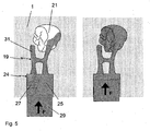
- FIG. 5 is the embodiment according to FIG. 2 shown in more detail during the pressing or after pressing.
- the second volume region 27 still travels along the second flow path via the leg to the blind channel 31, the transverse channel and the upper part of the leg connected to the mold cavity 31 to the mold cavity 31.
- the blind channel 31 is filled, because the pressure in the press-in direction has first pressed a first flow front of the second volume region 27 into the blind channel 31 until it is filled.
- the flow front of the second volume portion 27 follows the transverse channel and finally the pressure in the press-fit direction along the upper portion of the leg connected to the mold cavity 31 to the mold cavity 31.
- the flow path followed by the flow front of the second volume portion 27 has therefore, a larger volume than the flow path followed by the flow front of the first volume region 25 directly through the leg connected to the mold cavity 31 to the mold cavity 31.
- the volume regions 25, 27 recombine with each other.
- the mold cavity 31 has a higher volume fraction with the first volume region 25 than with the second volume region 27.
- Naturally acting color and opacity gradients thus become achieved the dental restoration.
- the pressed-in shaped body 24 is hardened.
- the mold 1 is then removed by cutting, milling, sandblasting, etching and / or other conventional methods.
- the dental restoration consisting of the filling of the mold cavity 31 is separated from the material, the shaped body 24, which fills the channel system 19.
- the location where the model 17 was attached to the abutment system 15 requires the dental restoration to be manually reworked to provide a mesial and dental surface of the dental restoration that conforms to the natural tooth. It is advantageous if the incitation of the model is performed not occlusally, but mesially or distally, because then the shape of the opposing teeth is not to be considered during the manual post-processing.
- FIGS. 7, 8 and 9 Another embodiment of the invention is in the FIGS. 7, 8 and 9 shown.
- This embodiment is particularly well suited for the simultaneous production of multiple dental restorations simultaneously.
- it is two dental restorations that are made simultaneously in one press fit, but it can be more.
- a molded article 24 is used as it is in FIG. 3b is shown.
- the volume regions 25, 27 and 35 are disk-shaped and together form the cylindrical shaped body 24.
- the volume region 25 here corresponds to the dentin mass, the volume region 27 of the cutting mass and the volume region 35 of the cervical dentin mass.
- the channel system 19 in the mold 1 has been produced in this example with a pin system 15, as shown in FIG.
- the Anstattsystem 15 essentially consists of a plate of eg Plexiglas or wax and can be inserted into a precisely fitting through slot on the front side of the recess 7 of the press muffle base 5. In this case, the Anchansystem 15 fills the slot completely and protrudes laterally from the lateral surfaces the recess 7 of the press muffle base 5. The models of the dental restorations are attached to these lateral projections.
- the Anstattsystem 15 also has an extension 30 which protrudes in the press-fitting from the end face of the recess 7 of the press muffle base 5.
- the Anchansystem 15 also sits centrally in the slot on the front side of the recess 7 of the Pressmuffelbasis 5, the Anchansystem 15 may have a spring 39 which engages in a corresponding groove 41 in the slot on the front side of the recess 7 of the Pressmuffelbasis 5 ,
- a third volume region 35 of the shaped body 24 lies directly on the end edge of the pressing space 23 and a reservoir 31, which results from the burned-on tapping system 15 with the extension 30.
- Further reservoirs 31 are arranged on the underside of the channel system 19 so that the flow path for the second volume region 27, ie the cutting mass, passes through the volume of the lower reservoir 31.
- the number and configuration of reservoirs 31 and their arrangement and orientation on the channel system 19 can be arbitrarily selected by the design of the tapping system 15.
- the first volume region 25 represents the middle layer to which the third volume region 35, namely the cervical dentin mass, adjoins, which is in direct contact with the pressing piston 29.
- FIG. 8 shows what happens when the molding 24 is pressed.
- the third volume region 35 is pressed into the reservoir 31 and also laterally into the channels, while the other volume regions 25, 27 are pressed exclusively laterally into the channels.
- the third volume region 35 Since the lateral pressure during the filling of the upper reservoir 31 increases with the distance to the upper reservoir 31, the third volume region 35 experiences a smaller lateral pressure than the other volume regions 25, 27, as long as the upper reservoir 31 is not yet filled. Only when the upper reservoir 31 is filled, the third volume region 35 is pressed with the same force as the other volume regions 25, 27 to the mold cavities 21. Similarly, the filling of the lower reservoir 31 extends with the second volume region 27, ie the cutting mass. As a result, less cutting mass is pressed into the mold cavities 21 as Dentinmasse. As in FIG.
- the third volume region 35 already has a residue on the other volume regions 25, 27, so that less volume of the mold cavities 21 is filled by the third volume region 35, ie the cervical dentin mass, than by the first volume region 25, ie the dentin mass. Because of the reservoirs 31 for the second volume region 27 and for the third volume region, a plurality of flow fronts partially extend into the reservoirs 31 and thus each form an entire flow path with a larger volume than the flow path of the first volume region 25.
- an H-shaped pin system 15 is shown as it is the first embodiment of FIG. 2 equivalent.
- the leg of the H-shaped pin system 15, which is not intended for the model 17, has an extension 30 in the upper part, which leads to a blind channel 31 when the mold 1 is produced. Since the length of the extension 30 affects the volume of the blind channel 31 and thus directly on the volume fraction of the second volume region 27 in the dental restoration, it makes sense if the length is adjustable for the user.
- the extension 30 thus has a scale by means of which the user can shorten the length of the extension 30 by cutting in order to achieve a desired distribution of the volume regions 25, 27 in the dental restoration.
- the expansions 30 of the second embodiment can also each have a scale for severing.
Landscapes
- Health & Medical Sciences (AREA)
- Oral & Maxillofacial Surgery (AREA)
- Dentistry (AREA)
- Epidemiology (AREA)
- Life Sciences & Earth Sciences (AREA)
- Animal Behavior & Ethology (AREA)
- General Health & Medical Sciences (AREA)
- Public Health (AREA)
- Veterinary Medicine (AREA)
- Dental Prosthetics (AREA)
- Compositions Of Oxide Ceramics (AREA)
Claims (21)
- Procédé de fabrication de restaurations dentaires en céramique, en vue d'obtenir des gradients de couleur et d'opacité naturels, selon lequel
un corps à mouler (24) en céramique est pressé à travers un système de canaux (19), prévu dans un moule (1), en partie ou en totalité dans une empreinte (21) du moule, qui correspond à une restauration dentaire, selon lequel
le corps à mouler (24) présente une première zone de volume (25) et une deuxième zone de volume (27), la deuxième zone (27) se distinguant de la première zone (25) par une couleur ou une opacité différente, et selon lequel
le système de canaux (19) dans le moule (1) guide le corps à mouler (24), lors de la pressée, dans l'empreinte (21) de manière telle que la matière de la première zone de volume (25) arrive dans l'empreinte (21) avant la matière de la deuxième zone de volume (27) et/ou une quantité de matière de la première zone de volume (25) est pressée dans l'empreinte (21), qui est plus grande que la quantité de matière de la deuxième zone de volume (27), caractérisé par le fait que
le système de canaux (19) comporte deux chemins d'écoulement vers l'empreinte (21), le deuxième chemin d'écoulement ayant un volume plus important que le premier, et la matière de la première zone de volume (25) étant pressée dans l'empreinte (21) en passant par le premier chemin d'écoulement, et la matière de la deuxième zone de volume (27) étant pressée dans l'empreinte (21) en passant par le deuxième chemin d'écoulement. - Procédé selon la revendication 1, selon lequel le deuxième chemin d'écoulement du système de canaux (19) présente un réservoir (31) et, lors de la pressée, de la matière provenant de la deuxième zone de volume (27) est poussée dans ce réservoir (31).
- Procédé selon une des revendications précédentes, selon lequel, avant la pressée, un modèle (17) d'une restauration dentaire, constitué d'un matériau pouvant être éliminé entièrement par fusion et doté d'un système de fixation (15) en un matériau pouvant être éliminé entièrement par fusion, est installé sur un socle (5) de four de pressée (3), le four (3) est rempli avec une masse d'enrobage de manière à ce que le modèle (17) et le système de fixation (15) soient entourés entièrement par cette masse, la masse d'enrobage est durcie pour obtenir un moule (1) réfractaire, et le modèle (17) ainsi que le système de fixation (15) sont éliminés par fusion pour réaliser dans le moule (1) durci une empreinte (21), correspondant à une restauration dentaire, ainsi que le système de canaux (19).
- Procédé selon la revendication 3, selon lequel le modèle (17) d'une restauration dentaire est relié de manière mésiale ou distale au système de fixation (15).
- Système de fabrication de restaurations dentaires en céramique, en vue d'obtenir des gradients de couleur et d'opacité naturels, ledit système comprenant
un corps à mouler (24) en céramique,
un socle de four de pressée (5), et
un système de fixation (15) en un matériau pouvant être éliminé entièrement par fusion, où
le système de fixation (15) sert à monter un modèle (17) d'une restauration dentaire, constitué d'un matériau pouvant être éliminé entièrement par fusion, sur le socle de four de pressée (5), de sorte que ledit modèle (17), fixé au socle de four de pressée (5) à l'aide du système de fixation (15), permet de réaliser un moule (1) avec un système de canaux (19), correspondant au système de fixation (15), et une empreinte (21) correspondant au modèle (17), et un moule (1) ainsi réalisé est adapté pour presser le corps à mouler (24) dans l'empreinte (21) du moule (1), où
le corps à mouler (24) présente une première zone de volume (25) et une deuxième zone de volume (27), la deuxième zone (27) se distinguant de la première zone (25) par une couleur ou une opacité différente, caractérisé par le fait que
le système de fixation (15) est préfabriqué et agencé de manière telle que le système de canaux (19) créé lors d'une réalisation du moule (1) comporte deux chemins d'écoulement, le deuxième chemin d'écoulement ayant un volume plus important que le premier et, lors d'une pressée, la matière de la première zone de volume (25) étant pressée dans l'empreinte (21) en passant par le premier chemin d'écoulement, et la matière de la deuxième zone de volume (27) étant pressée dans l'empreinte (21) en passant par le deuxième chemin d'écoulement. - Système selon la revendication 5, dans lequel les zones de volume (25, 27, 35) du corps à mouler (24) se présentent sous forme de parties séparées du corps à mouler (24) et sont appropriées pour fondre et former un corps à mouler (24), sous l'effet d'un réchauffage et/ou d'une compression.
- Système selon la revendication 5 ou 6, dans lequel le système de fixation est doté d'une extension (30) de manière à former, lors de la réalisation d'un moule (1), un réservoir (31) en tant que partie du deuxième chemin d'écoulement, le raccourcissement de l'extension (30), avant la réalisation du moule (1), permettant de réduire le volume de cette extension (30) et donc du réservoir (31) formé.
- Système selon les revendications 5 à 7, dans lequel le système de fixation (15) est agencé pour relier deux ou plus de deux modèles (17) de restaurations dentaires au socle de four de pressée (5).
- Système selon une des revendications 5 à 8, dans lequel le gradient de couleur ou d'opacité entre les zones de volume (25, 27, 35) du corps à mouler (24) est constant..
- Système selon une des revendications 5 à 9, dans lequel le corps à mouler (24) présente un sens de pressée dans lequel le profil transversal du corps à mouler (24) est constant.
- Système selon la revendication 10, dans lequel le corps à mouler (24) a une forme sensiblement cylindrique.
- Système selon la revendication 10 ou 11, dans lequel la première zone de volume (25) et la deuxième zone de volume (27) du corps à mouler (24) s'étendent sensiblement dans le sens de pressée et sont contiguës l'une à l'autre dans un plan avec une normale qui est sensiblement perpendiculaire au sens de pression du corps à mouler (24).
- Système selon la revendication 10 ou 11, dans lequel la première zone de volume (25) et la deuxième zone de volume (27) constituent chacune sensiblement une couche du corps à mouler (24) et sont contiguës l'une à l'autre dans un plan avec une normale qui est sensiblement parallèle au sens de pressée du corps à mouler (24).
- Système selon la revendication 10 ou 11, dans lequel la première zone de volume (25) et la deuxième zone de volume (27) forment chacune sensiblement une portion du corps à mouler (24) et sont contiguës l'une à l'autre dans un plan avec une normale qui s'étend en biais par rapport au sens de pressée du corps à mouler (24).
- Système selon une des revendications 5 à 14, dans lequel le corps à mouler (24) présente, en plus des première (25) et deuxième (27) zones de volume, au moins une zone de volume (35) supplémentaire qui se distingue d'une zone de volume (25, 27) voisine par une couleur ou une opacité différente.
- Système selon une des revendications 10 à 15, dans lequel le corps à mouler (24) présente une interruption de la symétrie de révolution dans le sens de pressée, de sorte que lors de la pressée, une orientation univoque du corps à mouler (24) est garantie dans un plan avec une normale qui est sensiblement parallèle au sens de pressée du corps à mouler (24), à l'intérieur du moule (1).
- Système selon la revendication 16, dans lequel l'interruption de la symétrie de révolution, se présentant sous la forme d'une saillie, d'une rainure longitudinale, d'un plan oblique ou d'un méplat unilatéral sur le corps à mouler (24), a pour effet de garantir, lors de la pressée, une orientation univoque du corps à mouler (24) à l'intérieur du moule (1), dans un plan avec une normale qui est sensiblement parallèle au sens de pressée.
- Système selon une des revendications 5 à 17, dans lequel le socle de four de pressée (5) comporte un élément creux (7) qui correspond sensiblement à la forme du corps à mouler (24), de sorte que lors de la réalisation du moule (1), cet élément creux (7) crée une cavité de pressée (23) dans le moule (1), dans laquelle le corps à mouler (24) peut être engagé en vue de l'opération de pressée.
- Système selon la revendication 18, dans lequel la hauteur de l'élément creux (7) du socle de four de pressée (5) est réglable, de sorte que lors de la réalisation du moule (1), la hauteur de l'élément creux (7) crée une cavité de pressée (23) de profondeur correspondante dans le moule (1).
- Système selon une des revendications 5 à 19, dans lequel le matériau pouvant être éliminé entièrement par fusion du système de fixation (15) est du plexiglas ou de la cire.
- Utilisation d'un corps à mouler (24) en céramique pour fabriquer des restaurations dentaires en céramique, en vue d'obtenir des gradients de couleur et d'opacité naturels, le corps à mouler (24) présentant une première zone de volume (25) et une deuxième zone de volume (27), la deuxième zone (27) se distinguant de la première zone (25) par une couleur ou une opacité différente,
le corps à mouler (24) étant pressé à travers un système de canaux (19), prévu dans un moule (1), en partie ou en totalité dans une empreinte (21) du moule qui correspond à une restauration dentaire, et
le système de canaux (19) dans le moule (1) guidant le corps à mouler (24), lors de la pressée, dans l'empreinte (21) de manière telle que la matière de la première zone de volume (25) arrive dans l'empreinte avant la matière de la deuxième zone de volume (27) et/ou une quantité de matière provenant de la première zone de volume (25) est pressée dans l'empreinte (21), qui est plus grande que la quantité de matière de la deuxième zone de volume (27), caractérisé par le fait que
le système de canaux (19) comporte deux chemins d'écoulement vers l'empreinte (21), le deuxième chemin d'écoulement ayant un volume plus important que le premier, et la matière de la première zone de volume (25) étant pressée dans l'empreinte (21) en passant par le premier chemin d'écoulement, et la matière de la deuxième zone de volume (27) étant pressée dans l'empreinte (21) en passant par le deuxième chemin d'écoulement.
Priority Applications (6)
| Application Number | Priority Date | Filing Date | Title |
|---|---|---|---|
| DE502007003480T DE502007003480D1 (de) | 2007-11-28 | 2007-11-28 | Verfahren und System zur Herstellung von dentalen Restaurationen aus Keramik |
| EP07023059A EP2065012B1 (fr) | 2007-11-28 | 2007-11-28 | Procédé et système de fabrication de restaurations dentaires en céramique |
| AT07023059T ATE464018T1 (de) | 2007-11-28 | 2007-11-28 | Verfahren und system zur herstellung von dentalen restaurationen aus keramik |
| US12/055,818 US7845924B2 (en) | 2007-11-28 | 2008-03-26 | System for preparing dental restorations |
| JP2008297380A JP5137790B2 (ja) | 2007-11-28 | 2008-11-20 | セラミックからの歯科修復物を調製する方法およびシステム |
| US12/478,826 US7704421B2 (en) | 2007-11-28 | 2009-06-05 | Method for preparing dental restorations |
Applications Claiming Priority (1)
| Application Number | Priority Date | Filing Date | Title |
|---|---|---|---|
| EP07023059A EP2065012B1 (fr) | 2007-11-28 | 2007-11-28 | Procédé et système de fabrication de restaurations dentaires en céramique |
Publications (2)
| Publication Number | Publication Date |
|---|---|
| EP2065012A1 EP2065012A1 (fr) | 2009-06-03 |
| EP2065012B1 true EP2065012B1 (fr) | 2010-04-14 |
Family
ID=39277036
Family Applications (1)
| Application Number | Title | Priority Date | Filing Date |
|---|---|---|---|
| EP07023059A Active EP2065012B1 (fr) | 2007-11-28 | 2007-11-28 | Procédé et système de fabrication de restaurations dentaires en céramique |
Country Status (5)
| Country | Link |
|---|---|
| US (2) | US7845924B2 (fr) |
| EP (1) | EP2065012B1 (fr) |
| JP (1) | JP5137790B2 (fr) |
| AT (1) | ATE464018T1 (fr) |
| DE (1) | DE502007003480D1 (fr) |
Cited By (2)
| Publication number | Priority date | Publication date | Assignee | Title |
|---|---|---|---|---|
| EP3235467A1 (fr) | 2016-04-22 | 2017-10-25 | Ivoclar Vivadent AG | Méthode de fabrication d'une restauration dentaire |
| EP3829482B1 (fr) * | 2018-08-02 | 2024-11-06 | Ivoclar Vivadent AG | Ébauche multicolore à des fins dentaires |
Families Citing this family (15)
| Publication number | Priority date | Publication date | Assignee | Title |
|---|---|---|---|---|
| DE502007003480D1 (de) * | 2007-11-28 | 2010-05-27 | Ivoclar Vivadent Ag | Verfahren und System zur Herstellung von dentalen Restaurationen aus Keramik |
| DE102008017784B4 (de) * | 2008-04-08 | 2014-04-17 | Ivoclar Vivadent Ag | Vorrichtung zum Anfertigen einer Muffel |
| US10582988B2 (en) * | 2012-05-03 | 2020-03-10 | 3Shape A/S | Automated production of dental restoration |
| ES2908581T3 (es) * | 2012-10-02 | 2022-05-03 | 3Shape As | Molde para restauración dental |
| EP2765119B1 (fr) | 2013-02-12 | 2021-07-28 | Ivoclar Vivadent AG | Ébauche à des fins dentaires |
| US11376104B2 (en) | 2013-12-20 | 2022-07-05 | Ivoclar Vivadent Ag | Method for processing a dental material and a dental furnace |
| EP3178441B1 (fr) * | 2013-12-20 | 2019-09-04 | Ivoclar Vivadent AG | Procédé de traitement d'un matériau dentaire, dispositif de réglage pour un four dentaire et four dentaire |
| CN105960216B (zh) * | 2014-02-21 | 2020-06-19 | 株式会社Gc | 牙科修补物的制造方法 |
| US10507090B2 (en) * | 2014-08-12 | 2019-12-17 | Hangzhou Erran Technology Co., Ltd. | Dental all-ceramic restoration and manufacturing method thereof |
| EP3064169B1 (fr) * | 2015-03-04 | 2019-04-24 | Ivoclar Vivadent AG | Procédé de fabrication de pièces céramiques dentaires et appareils pour la fabrication de pièces de céramique dentaire |
| KR101881280B1 (ko) * | 2017-11-02 | 2018-07-26 | 김영수 | 잉곳 일체형 일회용 플런저 조립체 |
| US10974997B2 (en) | 2018-01-29 | 2021-04-13 | James R. Glidewell Dental Ceramics, Inc. | Polychromatic zirconia bodies and methods of making the same |
| JP6857634B2 (ja) * | 2018-06-29 | 2021-04-14 | 株式会社ジーシー | 歯科補綴物成型用器具、歯科補綴物の製造方法 |
| DE102018119078A1 (de) * | 2018-08-06 | 2020-02-06 | Redios-Tec Gmbh | Verfahren zur Herstellung eines Dentalbauteils |
| JP6619857B2 (ja) * | 2018-09-05 | 2019-12-11 | 株式会社ジーシー | セラミックスブランク |
Family Cites Families (31)
| Publication number | Priority date | Publication date | Assignee | Title |
|---|---|---|---|---|
| GB514830A (en) * | 1937-05-12 | 1939-11-20 | Reichsverband Deutscher Dentis | Artificial denture parts and process for their manufacture |
| US3064309A (en) * | 1954-12-03 | 1962-11-20 | Edmund A Steinbock | Mold former |
| US3909169A (en) * | 1972-01-20 | 1975-09-30 | Ici Ltd | Injection moulding apparatus |
| DE2346135C2 (de) * | 1973-09-13 | 1982-11-04 | Battenfeld Maschinenfabriken Gmbh, 5882 Meinerzhagen | Verfahren und Vorrichtung zum Spritzgießen von Kunststofformkörpern, die aus einer Füllschicht aus einem thermoplastischen Kunststoff und aus einer diese einschließenden Deckschicht aus einem anderen thermoplastischen Kunststoff bestehen |
| US4189325A (en) * | 1979-01-09 | 1980-02-19 | The Board of Regents, State of Florida, University of Florida | Glass-ceramic dental restorations |
| US4573842A (en) * | 1983-02-24 | 1986-03-04 | General Motors Corporation | Resilient tie-down device |
| JPS60158856A (ja) * | 1984-01-28 | 1985-08-20 | 九州耐火煉瓦株式会社 | セラミツクス鋳造歯科修復材のスプル−イング法 |
| US4573921A (en) * | 1984-06-27 | 1986-03-04 | Berger Robert P | Prosthesis and apparatus for molding the prosthesis |
| JPH0714826B2 (ja) * | 1985-07-05 | 1995-02-22 | オリンパス光学工業株式会社 | ガラスセラミツクス製歯冠およびその製造方法 |
| CH668699A5 (de) | 1986-01-17 | 1989-01-31 | Sonja Wohlwend Erne | Verfahren zum herstellen von zahnersatzteilen. |
| GB8616460D0 (en) * | 1986-07-05 | 1986-08-13 | Metal Box Plc | Manufacture of articles |
| JP2721767B2 (ja) * | 1991-12-19 | 1998-03-04 | 光昭 岩井 | 歯科用補綴物鋳造鋳型成形用スプルー形態 |
| US6485849B2 (en) * | 1994-05-31 | 2002-11-26 | Tec Ventures, Inc. | Method for molding dental restorations and related apparatus |
| US5507981A (en) | 1994-05-31 | 1996-04-16 | Tel Ventures, Inc. | Method for molding dental restorations |
| DE19747573C5 (de) * | 1996-10-29 | 2007-10-18 | Kabushiki Kaisha Kobe Seiko Sho (Kobe Steel, Ltd.), Kobe | Spritzeinheitsverbindungsvorrichtung für eine Mehrschichtspritzformmaschine |
| DE19714178C2 (de) * | 1997-04-07 | 2003-09-18 | Ivoclar Vivadent Ag | Verfahren zur Herstellung eines mehrfarbigen Formkörpers für die Weiterverarbeitung zu einer Zahnrestauration und zugehöriger Formkörper |
| JPH11216148A (ja) * | 1998-01-30 | 1999-08-10 | Shiyuukai | クラウン・ブリッジ |
| US6655945B1 (en) * | 1999-03-18 | 2003-12-02 | Mold Masters Limited | Apparatus and method for multi-layer injection molding |
| JP2001061864A (ja) * | 1999-08-27 | 2001-03-13 | Dental Supply:Kk | 金属歯冠の製造法と該製造に用いる歯冠咬合部成形用型材 |
| US6740267B1 (en) * | 1999-09-20 | 2004-05-25 | Tokuyama Corporation | Method of producing ceramic crowns |
| DE10241857B4 (de) * | 2001-10-02 | 2005-01-20 | Michael Polz | Verfahren und Vorrichtung zur Anfertigung einer Form, insbesondere einer Muffel, für die Herstellung von Zahnersatz-Objekten |
| DE10237982A1 (de) * | 2002-08-14 | 2004-02-26 | Zubler Gerätebau GmbH | Verfahren zur Herstellung von Zahnersatz aus Preßkeramik in der Dentaltechnik; Kermikpreßofen und Muffel hierfür |
| ATE336957T1 (de) * | 2003-06-13 | 2006-09-15 | Ivoclar Vivadent Ag | Verfahren zur herstellung einer zahnrestauration und entsprechendes gerät |
| EP1654998B1 (fr) * | 2003-07-17 | 2014-05-07 | Kuraray Noritake Dental Inc. | Procédé de production d'une prothèse dentaire et nécessaire utilisé avec ce procédé |
| ATE416711T1 (de) * | 2003-12-17 | 2008-12-15 | Degudent Gmbh | Verfahren zum herstellen einer dentalkeramischen struktur |
| FR2883720B1 (fr) * | 2005-03-31 | 2008-01-25 | Germinal Veyrat | Prothese dentaire ceramique, procede et dispositif pour sa realisation |
| US20070057391A1 (en) * | 2005-08-05 | 2007-03-15 | Den-Mat Corporation | Method for forming ceramic ingot |
| DK2359771T3 (en) * | 2006-05-23 | 2016-08-29 | Ivoclar Vivadent Ag | A process for the preparation of colored blanks and dental form pieces. |
| US7547208B2 (en) * | 2006-06-16 | 2009-06-16 | Mold-Masters (2007) Limited | Individual cavity shut-off valve for an injection molding apparatus |
| US8257622B2 (en) * | 2007-11-05 | 2012-09-04 | Ivoclar Vivadent Ag | Muffle and method of using |
| DE502007003480D1 (de) * | 2007-11-28 | 2010-05-27 | Ivoclar Vivadent Ag | Verfahren und System zur Herstellung von dentalen Restaurationen aus Keramik |
-
2007
- 2007-11-28 DE DE502007003480T patent/DE502007003480D1/de active Active
- 2007-11-28 EP EP07023059A patent/EP2065012B1/fr active Active
- 2007-11-28 AT AT07023059T patent/ATE464018T1/de active
-
2008
- 2008-03-26 US US12/055,818 patent/US7845924B2/en active Active
- 2008-11-20 JP JP2008297380A patent/JP5137790B2/ja active Active
-
2009
- 2009-06-05 US US12/478,826 patent/US7704421B2/en active Active
Cited By (3)
| Publication number | Priority date | Publication date | Assignee | Title |
|---|---|---|---|---|
| EP3235467A1 (fr) | 2016-04-22 | 2017-10-25 | Ivoclar Vivadent AG | Méthode de fabrication d'une restauration dentaire |
| WO2017182173A1 (fr) * | 2016-04-22 | 2017-10-26 | Ivoclar Vivadent Ag | Procédé de production d'une restauration dentaire |
| EP3829482B1 (fr) * | 2018-08-02 | 2024-11-06 | Ivoclar Vivadent AG | Ébauche multicolore à des fins dentaires |
Also Published As
| Publication number | Publication date |
|---|---|
| ATE464018T1 (de) | 2010-04-15 |
| DE502007003480D1 (de) | 2010-05-27 |
| JP5137790B2 (ja) | 2013-02-06 |
| US20090239199A1 (en) | 2009-09-24 |
| JP2009131630A (ja) | 2009-06-18 |
| US7845924B2 (en) | 2010-12-07 |
| US7704421B2 (en) | 2010-04-27 |
| US20090136901A1 (en) | 2009-05-28 |
| EP2065012A1 (fr) | 2009-06-03 |
Similar Documents
| Publication | Publication Date | Title |
|---|---|---|
| EP2065012B1 (fr) | Procédé et système de fabrication de restaurations dentaires en céramique | |
| EP3053541B1 (fr) | Ébauche destinee a fabriquer une prothese dentaire | |
| AT404896B (de) | Künstlicher zahn | |
| EP3649983B1 (fr) | Procédé de fabrication de prothèses dentaires | |
| WO2017198514A1 (fr) | Dispositif de rétention ainsi que procédé pour sa fabrication | |
| EP2111180A1 (fr) | Procédé de modélisation et de fabrication d'une mâchoire artificielle | |
| EP3463178B1 (fr) | Procédé de fabrication de prothèse dentaire | |
| EP2026711A1 (fr) | Ébauche pour une partie de prothèse dentaire et procédé de fabrication d'une partie de prothèse dentaire | |
| WO2015185381A1 (fr) | Dispositif de production d'une céramique dentaire | |
| DE102011004551B4 (de) | Verfahren zur Herstellung einer Anzahl dentaler Restaurationen | |
| WO2020057872A1 (fr) | Demi-produit pour la fabrication de dents prothétiques et procédé pour sa fabrication et son traitement | |
| EP1138272A1 (fr) | Procédé de fabrication d'une prothèse dentaire | |
| EP4308037B1 (fr) | Procédé de fabrication de couches structurées pour matériaux de fabrication de prothèses dentaires, et dispositif à cet effet | |
| EP1264581B1 (fr) | Dent artificielle et son procédé de fabrication | |
| EP3157460B1 (fr) | Base de prothèse et procédé pour relier par liaison de matière au moins une dent artificielle à une base de prothèse | |
| EP2965710A1 (fr) | Moules personnalisées | |
| EP3151781A1 (fr) | Modèle de restauration dentaire | |
| DE4023088A1 (de) | Vorrichtung und verfahren zum erstellen von zweiteiligen kronen | |
| EP3064169B1 (fr) | Procédé de fabrication de pièces céramiques dentaires et appareils pour la fabrication de pièces de céramique dentaire | |
| DE19752756C1 (de) | Verfahren zum Herstellen von Schmuckstücken und danach hergestelltes Schmuckstück | |
| DE102024138853A1 (de) | Verfahren zum Herstellen von Zahnersatz | |
| DE202014103288U1 (de) | Muffelform zur Herstellung von zahnprothetischen Formkörpern, daraus hergestellter zahnprothetischer Formkörper und Modell zur Herstellung einer Muffelform | |
| EP3245976A1 (fr) | Procédé de fabrication d'une prothèse dentaire | |
| EP1827292A1 (fr) | Dispositif pour mouler une base de prothese pour une prothese dentaire |
Legal Events
| Date | Code | Title | Description |
|---|---|---|---|
| PUAI | Public reference made under article 153(3) epc to a published international application that has entered the european phase |
Free format text: ORIGINAL CODE: 0009012 |
|
| 17P | Request for examination filed |
Effective date: 20080605 |
|
| AK | Designated contracting states |
Kind code of ref document: A1 Designated state(s): AT BE BG CH CY CZ DE DK EE ES FI FR GB GR HU IE IS IT LI LT LU LV MC MT NL PL PT RO SE SI SK TR |
|
| AX | Request for extension of the european patent |
Extension state: AL BA HR MK RS |
|
| GRAP | Despatch of communication of intention to grant a patent |
Free format text: ORIGINAL CODE: EPIDOSNIGR1 |
|
| RTI1 | Title (correction) |
Free format text: METHOD AND SYSTEM FOR MANUFACTURING DENTAL RESTORATIONS MADE OF CERAMIC |
|
| GRAS | Grant fee paid |
Free format text: ORIGINAL CODE: EPIDOSNIGR3 |
|
| AKX | Designation fees paid |
Designated state(s): AT BE BG CH CY CZ DE DK EE ES FI FR GB GR HU IE IS IT LI LT LU LV MC MT NL PL PT RO SE SI SK TR |
|
| GRAA | (expected) grant |
Free format text: ORIGINAL CODE: 0009210 |
|
| RIN1 | Information on inventor provided before grant (corrected) |
Inventor name: CADARIO, VITTORIO Inventor name: BUERKE, HARALD Inventor name: SCHWEIGER, MARCEL Inventor name: RHEINBERGER, VOLKER |
|
| AK | Designated contracting states |
Kind code of ref document: B1 Designated state(s): AT BE BG CH CY CZ DE DK EE ES FI FR GB GR HU IE IS IT LI LT LU LV MC MT NL PL PT RO SE SI SK TR |
|
| REG | Reference to a national code |
Ref country code: GB Ref legal event code: FG4D Free format text: NOT ENGLISH |
|
| REG | Reference to a national code |
Ref country code: CH Ref legal event code: EP Ref country code: CH Ref legal event code: NV Representative=s name: KELLER & PARTNER PATENTANWAELTE AG |
|
| REG | Reference to a national code |
Ref country code: IE Ref legal event code: FG4D Free format text: LANGUAGE OF EP DOCUMENT: GERMAN |
|
| REF | Corresponds to: |
Ref document number: 502007003480 Country of ref document: DE Date of ref document: 20100527 Kind code of ref document: P |
|
| REG | Reference to a national code |
Ref country code: NL Ref legal event code: T3 |
|
| LTIE | Lt: invalidation of european patent or patent extension |
Effective date: 20100414 |
|
| PG25 | Lapsed in a contracting state [announced via postgrant information from national office to epo] |
Ref country code: SE Free format text: LAPSE BECAUSE OF FAILURE TO SUBMIT A TRANSLATION OF THE DESCRIPTION OR TO PAY THE FEE WITHIN THE PRESCRIBED TIME-LIMIT Effective date: 20100414 Ref country code: LT Free format text: LAPSE BECAUSE OF FAILURE TO SUBMIT A TRANSLATION OF THE DESCRIPTION OR TO PAY THE FEE WITHIN THE PRESCRIBED TIME-LIMIT Effective date: 20100414 Ref country code: ES Free format text: LAPSE BECAUSE OF FAILURE TO SUBMIT A TRANSLATION OF THE DESCRIPTION OR TO PAY THE FEE WITHIN THE PRESCRIBED TIME-LIMIT Effective date: 20100725 |
|
| REG | Reference to a national code |
Ref country code: IE Ref legal event code: FD4D |
|
| PG25 | Lapsed in a contracting state [announced via postgrant information from national office to epo] |
Ref country code: SI Free format text: LAPSE BECAUSE OF FAILURE TO SUBMIT A TRANSLATION OF THE DESCRIPTION OR TO PAY THE FEE WITHIN THE PRESCRIBED TIME-LIMIT Effective date: 20100414 Ref country code: IS Free format text: LAPSE BECAUSE OF FAILURE TO SUBMIT A TRANSLATION OF THE DESCRIPTION OR TO PAY THE FEE WITHIN THE PRESCRIBED TIME-LIMIT Effective date: 20100814 Ref country code: FI Free format text: LAPSE BECAUSE OF FAILURE TO SUBMIT A TRANSLATION OF THE DESCRIPTION OR TO PAY THE FEE WITHIN THE PRESCRIBED TIME-LIMIT Effective date: 20100414 Ref country code: LV Free format text: LAPSE BECAUSE OF FAILURE TO SUBMIT A TRANSLATION OF THE DESCRIPTION OR TO PAY THE FEE WITHIN THE PRESCRIBED TIME-LIMIT Effective date: 20100414 |
|
| PG25 | Lapsed in a contracting state [announced via postgrant information from national office to epo] |
Ref country code: PL Free format text: LAPSE BECAUSE OF FAILURE TO SUBMIT A TRANSLATION OF THE DESCRIPTION OR TO PAY THE FEE WITHIN THE PRESCRIBED TIME-LIMIT Effective date: 20100414 Ref country code: CY Free format text: LAPSE BECAUSE OF FAILURE TO SUBMIT A TRANSLATION OF THE DESCRIPTION OR TO PAY THE FEE WITHIN THE PRESCRIBED TIME-LIMIT Effective date: 20100609 |
|
| PG25 | Lapsed in a contracting state [announced via postgrant information from national office to epo] |
Ref country code: EE Free format text: LAPSE BECAUSE OF FAILURE TO SUBMIT A TRANSLATION OF THE DESCRIPTION OR TO PAY THE FEE WITHIN THE PRESCRIBED TIME-LIMIT Effective date: 20100414 Ref country code: PT Free format text: LAPSE BECAUSE OF FAILURE TO SUBMIT A TRANSLATION OF THE DESCRIPTION OR TO PAY THE FEE WITHIN THE PRESCRIBED TIME-LIMIT Effective date: 20100816 Ref country code: IE Free format text: LAPSE BECAUSE OF FAILURE TO SUBMIT A TRANSLATION OF THE DESCRIPTION OR TO PAY THE FEE WITHIN THE PRESCRIBED TIME-LIMIT Effective date: 20100414 Ref country code: GR Free format text: LAPSE BECAUSE OF FAILURE TO SUBMIT A TRANSLATION OF THE DESCRIPTION OR TO PAY THE FEE WITHIN THE PRESCRIBED TIME-LIMIT Effective date: 20100715 Ref country code: DK Free format text: LAPSE BECAUSE OF FAILURE TO SUBMIT A TRANSLATION OF THE DESCRIPTION OR TO PAY THE FEE WITHIN THE PRESCRIBED TIME-LIMIT Effective date: 20100414 |
|
| PLBE | No opposition filed within time limit |
Free format text: ORIGINAL CODE: 0009261 |
|
| STAA | Information on the status of an ep patent application or granted ep patent |
Free format text: STATUS: NO OPPOSITION FILED WITHIN TIME LIMIT |
|
| PG25 | Lapsed in a contracting state [announced via postgrant information from national office to epo] |
Ref country code: SK Free format text: LAPSE BECAUSE OF FAILURE TO SUBMIT A TRANSLATION OF THE DESCRIPTION OR TO PAY THE FEE WITHIN THE PRESCRIBED TIME-LIMIT Effective date: 20100414 Ref country code: CZ Free format text: LAPSE BECAUSE OF FAILURE TO SUBMIT A TRANSLATION OF THE DESCRIPTION OR TO PAY THE FEE WITHIN THE PRESCRIBED TIME-LIMIT Effective date: 20100414 Ref country code: RO Free format text: LAPSE BECAUSE OF FAILURE TO SUBMIT A TRANSLATION OF THE DESCRIPTION OR TO PAY THE FEE WITHIN THE PRESCRIBED TIME-LIMIT Effective date: 20100414 |
|
| 26N | No opposition filed |
Effective date: 20110117 |
|
| BERE | Be: lapsed |
Owner name: IVOCLAR VIVADENT AG Effective date: 20101130 |
|
| PG25 | Lapsed in a contracting state [announced via postgrant information from national office to epo] |
Ref country code: MC Free format text: LAPSE BECAUSE OF NON-PAYMENT OF DUE FEES Effective date: 20101130 |
|
| PG25 | Lapsed in a contracting state [announced via postgrant information from national office to epo] |
Ref country code: BE Free format text: LAPSE BECAUSE OF NON-PAYMENT OF DUE FEES Effective date: 20101130 |
|
| PG25 | Lapsed in a contracting state [announced via postgrant information from national office to epo] |
Ref country code: IT Free format text: LAPSE BECAUSE OF NON-PAYMENT OF DUE FEES Effective date: 20101128 Ref country code: MT Free format text: LAPSE BECAUSE OF FAILURE TO SUBMIT A TRANSLATION OF THE DESCRIPTION OR TO PAY THE FEE WITHIN THE PRESCRIBED TIME-LIMIT Effective date: 20100414 |
|
| PG25 | Lapsed in a contracting state [announced via postgrant information from national office to epo] |
Ref country code: HU Free format text: LAPSE BECAUSE OF FAILURE TO SUBMIT A TRANSLATION OF THE DESCRIPTION OR TO PAY THE FEE WITHIN THE PRESCRIBED TIME-LIMIT Effective date: 20101015 Ref country code: LU Free format text: LAPSE BECAUSE OF NON-PAYMENT OF DUE FEES Effective date: 20101128 Ref country code: BG Free format text: LAPSE BECAUSE OF FAILURE TO SUBMIT A TRANSLATION OF THE DESCRIPTION OR TO PAY THE FEE WITHIN THE PRESCRIBED TIME-LIMIT Effective date: 20100414 |
|
| PG25 | Lapsed in a contracting state [announced via postgrant information from national office to epo] |
Ref country code: TR Free format text: LAPSE BECAUSE OF FAILURE TO SUBMIT A TRANSLATION OF THE DESCRIPTION OR TO PAY THE FEE WITHIN THE PRESCRIBED TIME-LIMIT Effective date: 20100414 |
|
| PG25 | Lapsed in a contracting state [announced via postgrant information from national office to epo] |
Ref country code: BG Free format text: LAPSE BECAUSE OF FAILURE TO SUBMIT A TRANSLATION OF THE DESCRIPTION OR TO PAY THE FEE WITHIN THE PRESCRIBED TIME-LIMIT Effective date: 20100714 |
|
| REG | Reference to a national code |
Ref country code: CH Ref legal event code: PCAR Free format text: NEW ADDRESS: EIGERSTRASSE 2 POSTFACH, 3000 BERN 14 (CH) |
|
| REG | Reference to a national code |
Ref country code: FR Ref legal event code: PLFP Year of fee payment: 9 |
|
| REG | Reference to a national code |
Ref country code: FR Ref legal event code: PLFP Year of fee payment: 10 |
|
| REG | Reference to a national code |
Ref country code: FR Ref legal event code: PLFP Year of fee payment: 11 |
|
| REG | Reference to a national code |
Ref country code: FR Ref legal event code: PLFP Year of fee payment: 12 |
|
| REG | Reference to a national code |
Ref country code: CH Ref legal event code: PFA Owner name: IVOCLAR VIVADENT AG, LI Free format text: FORMER OWNER: IVOCLAR VIVADENT AG, LI |
|
| P01 | Opt-out of the competence of the unified patent court (upc) registered |
Effective date: 20230607 |
|
| PGFP | Annual fee paid to national office [announced via postgrant information from national office to epo] |
Ref country code: AT Payment date: 20231004 Year of fee payment: 17 |
|
| REG | Reference to a national code |
Ref country code: AT Ref legal event code: MM01 Ref document number: 464018 Country of ref document: AT Kind code of ref document: T Effective date: 20241128 |
|
| PG25 | Lapsed in a contracting state [announced via postgrant information from national office to epo] |
Ref country code: AT Free format text: LAPSE BECAUSE OF NON-PAYMENT OF DUE FEES Effective date: 20241128 |
|
| PGFP | Annual fee paid to national office [announced via postgrant information from national office to epo] |
Ref country code: NL Payment date: 20251118 Year of fee payment: 19 |
|
| REG | Reference to a national code |
Ref country code: CH Ref legal event code: U11 Free format text: ST27 STATUS EVENT CODE: U-0-0-U10-U11 (AS PROVIDED BY THE NATIONAL OFFICE) Effective date: 20251218 |
|
| PGFP | Annual fee paid to national office [announced via postgrant information from national office to epo] |
Ref country code: DE Payment date: 20251118 Year of fee payment: 19 |
|
| PGFP | Annual fee paid to national office [announced via postgrant information from national office to epo] |
Ref country code: GB Payment date: 20251125 Year of fee payment: 19 |
|
| PGFP | Annual fee paid to national office [announced via postgrant information from national office to epo] |
Ref country code: IT Payment date: 20251119 Year of fee payment: 19 |
|
| PGFP | Annual fee paid to national office [announced via postgrant information from national office to epo] |
Ref country code: FR Payment date: 20251126 Year of fee payment: 19 |
|
| PGFP | Annual fee paid to national office [announced via postgrant information from national office to epo] |
Ref country code: CH Payment date: 20251218 Year of fee payment: 19 |