EP2065222A1 - Radialluftreifen - Google Patents
Radialluftreifen Download PDFInfo
- Publication number
- EP2065222A1 EP2065222A1 EP08019422A EP08019422A EP2065222A1 EP 2065222 A1 EP2065222 A1 EP 2065222A1 EP 08019422 A EP08019422 A EP 08019422A EP 08019422 A EP08019422 A EP 08019422A EP 2065222 A1 EP2065222 A1 EP 2065222A1
- Authority
- EP
- European Patent Office
- Prior art keywords
- elastic fiber
- fiber yarn
- highly
- yarn
- tire
- Prior art date
- Legal status (The legal status is an assumption and is not a legal conclusion. Google has not performed a legal analysis and makes no representation as to the accuracy of the status listed.)
- Granted
Links
Images
Classifications
-
- B—PERFORMING OPERATIONS; TRANSPORTING
- B60—VEHICLES IN GENERAL
- B60C—VEHICLE TYRES; TYRE INFLATION; TYRE CHANGING; CONNECTING VALVES TO INFLATABLE ELASTIC BODIES IN GENERAL; DEVICES OR ARRANGEMENTS RELATED TO TYRES
- B60C9/00—Reinforcements or ply arrangement of pneumatic tyres
- B60C9/18—Structure or arrangement of belts or breakers, crown-reinforcing or cushioning layers
- B60C9/20—Structure or arrangement of belts or breakers, crown-reinforcing or cushioning layers built-up from rubberised plies each having all cords arranged substantially parallel
- B60C9/22—Structure or arrangement of belts or breakers, crown-reinforcing or cushioning layers built-up from rubberised plies each having all cords arranged substantially parallel the plies being arranged with all cords disposed along the circumference of the tyre
- B60C9/2204—Structure or arrangement of belts or breakers, crown-reinforcing or cushioning layers built-up from rubberised plies each having all cords arranged substantially parallel the plies being arranged with all cords disposed along the circumference of the tyre obtained by circumferentially narrow strip winding
-
- B—PERFORMING OPERATIONS; TRANSPORTING
- B60—VEHICLES IN GENERAL
- B60C—VEHICLE TYRES; TYRE INFLATION; TYRE CHANGING; CONNECTING VALVES TO INFLATABLE ELASTIC BODIES IN GENERAL; DEVICES OR ARRANGEMENTS RELATED TO TYRES
- B60C9/00—Reinforcements or ply arrangement of pneumatic tyres
- B60C9/005—Reinforcements made of different materials, e.g. hybrid or composite cords
-
- D—TEXTILES; PAPER
- D02—YARNS; MECHANICAL FINISHING OF YARNS OR ROPES; WARPING OR BEAMING
- D02G—CRIMPING OR CURLING FIBRES, FILAMENTS, THREADS, OR YARNS; YARNS OR THREADS
- D02G3/00—Yarns or threads, e.g. fancy yarns; Processes or apparatus for the production thereof, not otherwise provided for
- D02G3/44—Yarns or threads characterised by the purpose for which they are designed
- D02G3/48—Tyre cords
-
- B—PERFORMING OPERATIONS; TRANSPORTING
- B60—VEHICLES IN GENERAL
- B60C—VEHICLE TYRES; TYRE INFLATION; TYRE CHANGING; CONNECTING VALVES TO INFLATABLE ELASTIC BODIES IN GENERAL; DEVICES OR ARRANGEMENTS RELATED TO TYRES
- B60C9/00—Reinforcements or ply arrangement of pneumatic tyres
- B60C9/18—Structure or arrangement of belts or breakers, crown-reinforcing or cushioning layers
- B60C9/20—Structure or arrangement of belts or breakers, crown-reinforcing or cushioning layers built-up from rubberised plies each having all cords arranged substantially parallel
- B60C9/22—Structure or arrangement of belts or breakers, crown-reinforcing or cushioning layers built-up from rubberised plies each having all cords arranged substantially parallel the plies being arranged with all cords disposed along the circumference of the tyre
- B60C2009/2214—Structure or arrangement of belts or breakers, crown-reinforcing or cushioning layers built-up from rubberised plies each having all cords arranged substantially parallel the plies being arranged with all cords disposed along the circumference of the tyre characterised by the materials of the zero degree ply cords
-
- D—TEXTILES; PAPER
- D10—INDEXING SCHEME ASSOCIATED WITH SUBLASSES OF SECTION D, RELATING TO TEXTILES
- D10B—INDEXING SCHEME ASSOCIATED WITH SUBLASSES OF SECTION D, RELATING TO TEXTILES
- D10B2331/00—Fibres made from polymers obtained otherwise than by reactions only involving carbon-to-carbon unsaturated bonds, e.g. polycondensation products
- D10B2331/02—Fibres made from polymers obtained otherwise than by reactions only involving carbon-to-carbon unsaturated bonds, e.g. polycondensation products polyamides
-
- Y—GENERAL TAGGING OF NEW TECHNOLOGICAL DEVELOPMENTS; GENERAL TAGGING OF CROSS-SECTIONAL TECHNOLOGIES SPANNING OVER SEVERAL SECTIONS OF THE IPC; TECHNICAL SUBJECTS COVERED BY FORMER USPC CROSS-REFERENCE ART COLLECTIONS [XRACs] AND DIGESTS
- Y10—TECHNICAL SUBJECTS COVERED BY FORMER USPC
- Y10T—TECHNICAL SUBJECTS COVERED BY FORMER US CLASSIFICATION
- Y10T152/00—Resilient tires and wheels
- Y10T152/10—Tires, resilient
- Y10T152/10495—Pneumatic tire or inner tube
- Y10T152/10765—Characterized by belt or breaker structure
Definitions
- the present invention relates to a pneumatic radial tire.
- the present invention relates to a pneumatic radial tire which includes a belt auxiliary reinforcement layer using general-purpose nylon fibers while its flat spot resistance is improved without sacrificing its high-speed durability.
- a conventional method for concurrently securing the high-speed durability and reducing the road noise of the tire has been to arrange a belt auxiliary reinforcement layer in the outer periphery of the belt layer of the tire.
- the belt auxiliary reinforcement layer is obtained by helically winding a heat-shrinkable organic fiber cord made of nylon or the like around the belt layer in the tire circumferential direction.
- the hybrid fiber cord for the belt auxiliary reinforcement layer
- the hybrid fiber cord is obtained by twisting together a highly-elastic fiber yarn made of polyketone or the like and a low-elastic fiber yarn made of a general-purpose nylon (such as nylon 66 and nylon 6).
- a general-purpose nylon such as nylon 66 and nylon 6
- the use of the general-purpose nylon 66 or nylon 6 for the low-elastic fiber yarn is advantageous in view of the high-speed durability because the general purpose nylon thermally shrinks to a large extent at higher temperature.
- the glass transition points of nylon 66 and nylon 6 are low, deformation once caused in the general-purpose nylon due to high heat generated during high-speed running is set into the general purpose nylon. This is likely to cause a problem so called flat spot phenomenon, in which the tire irregularly vibrates when the tire resumes running after stopping for a certain length of time.
- An object of the present invention is to solve the problems with the conventional radial tires by providing a pneumatic radial tire with a belt auxiliary reinforcement layer constituted of a hybrid fiber cord including a low-elastic fiber yarn using general-purpose nylon fibers.
- the radial tire has improved flat spot resistance without sacrificing its high-speed durability.
- a pneumatic radial tire of the present invention is characterized by including: multiple belt layers arranged in the outer periphery of a carcass layer in a tread part, an extending direction of cords in each of the belt layers intersecting that of cords in another one of the belt layers; and a belt auxiliary reinforcement layer formed by helically winding, in a tire circumferential direction, an organic fiber cord around the entire outer periphery of the belt layers and/or in the two end areas of the belt layers.
- the pneumatic radial tire is also characterized in that the organic fiber cord is constituted of a hybrid fiber cord obtained by twisting together a highly-elastic fiber yarn with an elastic modulus of 10000 MPa and a low-elastic fiber yarn made of nylon 46.
- the pneumatic radial tire configured in the above-described manner is further configured in such a way as to satisfy the following conditions (1) to (4).
- the belt auxiliary reinforcement layer is constituted of the hybrid fiber cord including the highly-elastic fiber yarn and the low-elastic fiber yarn, and the nylon 46 fibers having high glass transition point is used for the low-elastic fiber yarn. Accordingly, in the present invention, the elongation of the nylon 46 fibers prevents the cord from cutting into the belt layer during curing while the arresting effect of the highly-elastic fiber yarn secures high-speed durability.
- the low-elastic fiber yarn is made of nylon 46 having high glass transition point, the present invention is capable of ameliorating the set characteristics which is a deformation set by high heat generated during high-speed driving, thus improving the flat spot resistance of the pneumatic radial tire.
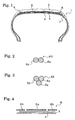
- Fig. 1 is a cross-sectional view showing a pneumatic radial tire according to an embodiment of the present invention.
- Fig. 2 is a cross-sectional view showing an example of a hybrid fiber cord constituting a belt auxiliary reinforcement layer according to the embodiment of the present invention.
- Fig. 3 is a cross-sectional view showing another example of the hybrid fiber cord constituting a belt auxiliary reinforcement layer according to the embodiment of the present invention.
- Fig. 4 is a cross-sectional view schematically showing an arrangement relationship between belt layers and a belt auxiliary reinforcement layer in a pneumatic radial tire according to another embodiment of the present invention by spreading out the belt layers and the belt auxiliary reinforcement layer into flat sheets.
- Fig. 1 is a cross-sectional view showing a pneumatic radial tire according to an embodiment of the present invention.
- Fig. 2 is a cross-sectional view showing an example of a hybrid fiber cord constituting a belt auxiliary reinforcement layer.
- a pneumatic radial tire 1 includes plural belt layers (two in Fig. 1 ) 4, 5 which are arranged in the outer periphery of a carcass layer 3 in a tread part 3. The directions in which the cords extend in the belt layer 4 and the belt layer 5 intersect each other.
- a belt auxiliary reinforcement layer 6 is formed by helically winding an organic fiber cord, in the tire circumferential direction, around the entire outer periphery of the belt layers 4, 5 and at the two end areas of the belt layers 4, 5. As shown in Fig.
- the organic fiber cord is constituted of a hybrid fiber cord 6z obtained by twisting together a highly-elastic fiber yarn 6P with an elastic modulus of 10000Mpa or more and a low-elastic fiber yarn 6q made of nylon 46.
- the belt auxiliary reinforcement layers 6 are each constituted of the hybrid fiber cord 6z obtained by twisting together the highly-elastic fiber yarn 6P with an elastic modulus of 10000Mpa or more and the low-elastic fiber yarn 6q made of nylon 46, it is possible to prevent the belt auxiliary reinforcement layer 6 from cutting into the belt layers 4, 5 during curing by elongation of nylon 46 fibers constituting the low-elastic fiber yarn 6q, while securing the high-speed durability for the pneumatic radial tire by the arresting effect of the highly-elastic fiber yarn 6p.
- the low-elastic fiber yarn 6q is made of nylon 46 having high glass transition point, the use of nylon 46 prevents deformation from being set into the belt auxiliary reinforcement layer due to high heat generated during high-speed driving. Thus, the flat spot resistance of the pneumatic radial tire is improved.
- the elastic modulus of the above-described highly-elastic fiber yarn 6p was obtained through a tensile test applied to a yarn in accordance with JIS (Japanese Industrial Standards) L1017-2002 "Test Methods for Chemical Fiber Tire Cords.”
- the yarn was obtained by untwisting the cord taken from the tire.
- the angle between the extending direction of a cord in each of the belt layers 4, 5 and the tire circumferential direction is desirable to set the angle between the extending direction of a cord in each of the belt layers 4, 5 and the tire circumferential direction to 24° to 35°. It is more desirable to set the angle to 27° to 33°. The angle thus selected makes it possible to improve both the high-speed durability and the flat spot resistance in a balanced manner.
- the hybrid fiber cord 6z with a three-yarn twisted structure in which two highly-elastic fiber yarns 6p and one low-elastic fiber yarn 6q are twisted together.
- the three-yarn twisted structure stabilizes the form of the cord, and thus further improves the flat spot resistance of the tire.
- the three-yarn twisted structure improves the fatigue resistance, and thus further enhances the high-speed durability of the tire.
- the number of first twists of the low-elastic fiber yarn 6q is smaller than that of the highly-elastic fiber yarn 6p.
- the ratio L/H is controlled so as to be set between 0.60 and 0.90.
- L denotes the first twist coefficient of the low-elastic fiber yarn 6q
- H denotes the first twist coefficient of the highly-elastic fiber yarn 6p. It is more desirable that the ratio L/H is controlled so as to be set between 0.69 and 0.80.
- the controlling of the ratio L/H in this manner increases the shrink properties of the hybrid fiber cord 6z, and thus enhances the hoop effects of the respective belt layers 4, 5 during high speed drive, and improves the high-speed durability of the tire.
- the permanent tensile deformation of a sample taken from a coating rubber coating the cord of each of the belt layers 4, 5 is controlled so as to be 3.0% or less. It is more desirable to control the permanent tensile deformation so as to be 2.5% or less.
- the controlling of the permanent tensile deformation in this manner eases the heat setting of the cords in the belt layers 4, 5 at the footprint part of the tire, and thus further improves the flat spot resistance.
- NR natural rubber
- SBR stylene-butadiene rubber
- BR butadiene rubber
- IR isoplene rubber
- the amount of sulfur used for the coating rubber should be 4.0 to 8.0 parts by weight, more preferably 5.0 to 7.5 parts by weight, per 100 parts by weight of rubber.
- the above-described permanent tensile deformation is obtained by calculating L ⁇ 1 - L ⁇ 0 / L ⁇ 0 ⁇ 100 % where L0 denotes the length of a rubber piece sampled out from the tire after curing, and L1 denotes the length of a rubber piece which is obtained by: applying tensile deformation, by 25% of its original length, to the rubber piece with a length L0 sampled out from the post-cured tire; subsequently leaving the rubber piece thus deformed in an atmosphere of 70°C for 1 hour; thereafter leaving the resultant rubber piece in an atmosphere of 25°C for 22 hours; after that, releasing the rubber piece from the deformation; and then leaving the thus-released rubber piece in an atmosphere of 25°C for 1 hour.
- the belt auxiliary reinforcement layers 6 is arranged in the entire outer periphery of the belt layer 5 and in the two end areas thereof.
- the arrangement of the belt auxiliary reinforcement layers 6 is not limited to this case.
- the belt auxiliary reinforcement layer 6 may be arranged only in the entire outer periphery of the belt layer 5 or only in the each of two end areas of the belt layer 5.
- the belt auxiliary reinforcement layer 6 may be arranged in such a way as to be divided into multiple blocks in the tire width direction.
- Fig. 4 is a cross-sectional view schematically showing an arrangement relationship between the belt layers 4, 5 and the belt auxiliary reinforcement layer 6 in a pneumatic radial tire according to another embodiment of the present invention by spreading out the belt layers 4, 5 and the belt auxiliary reinforcement layer 6 into flat sheets.
- the belt auxiliary reinforcement layer 6 is divided into: a block located in the center area of the tire; and two blocks located in the respective two end areas of the tire.
- a belt auxiliary reinforcement layer 6a arranged in the center area of the tire and belt auxiliary reinforcement layers 6b, 6b arranged in the respective two end areas of the tire may be constituted of the same type of organic fiber cord or may be of different types between the center area of the tire and the two end areas of the tire.
- the hybrid fiber cord obtained by twisting together the highly-elastic fiber yarn 6P with an elastic modulus of 10000 MPa or more and the low-elastic fiber yarn 6q made of nylon 46 is used for any one of the belt auxiliary reinforcement layers 6a and 6b.
- the belt auxiliary reinforcement layer 6a and the belt auxiliary reinforcement layer 6b, 6b may be arranged with a predetermined interval between each two neighboring belt auxiliary reinforcement layers as shown in Fig. 4 , or with no interval between each two neighboring belt auxiliary reinforcement layers.
- the hybrid fiber cord 6z obtained by twisting together the above mentioned highly-elastic fiber yarn 6p with an elastic modulus of 10000 MPa or more and the low-elastic fiber yarn 6q made of nylon 46 may be used for the belt auxiliary reinforcement layer 6a arranged in the center area.
- an organic fiber cord made of fibers such as aramid fibers having higher elastic modulus may be used for the belt auxiliary reinforcement layers 6b, 6b arranged in the respective two end areas.
- the hybrid fiber cord 6z obtained by twisting together the highly-elastic fiber yarn 6p with an elastic modulus of 10000 MPa or more and the low-elastic fiber yarn 6q made of nylon 46 may be used for the belt auxiliary reinforcement layer 6b, 6b arranged in the respective two end areas, whereas an organic fiber cord having lower elastic modulus than the elastic modulus may be used for the belt auxiliary reinforcement layer 6a arranged in the center area.
- the pneumatic radial tire according to the present invention uses the nylon 46 fibers having higher glass transition point instead of the general-purpose nylon fibers which, in the conventional type of tire, is included in the hybrid fiber cord that constitute the belt auxiliary reinforcement layer. Thereby, a high-level high-speed durability is secured while the flat spot resistance of the pneumatic radial tire is improved. For this reason, the pneumatic radial tire according to the present invention is applicable to high-performance automobiles of recent years in a desirable manner.
- a conventional tire (Conventional Example 1) using a hybrid fiber cord obtained by twisting together an aramid fiber yarn and a nylon 66 fiber yarn for the belt auxiliary reinforcement layer and a tire according to the present invention (Example 1) using a hybrid fiber cord obtained by twisting together an aramid fiber yarn and a nylon 46 fiber yarn for the belt auxiliary reinforcement layer were produced, as shown in Table 1. Both tires have tire sizes of 245/40R18 and tire structures as shown in Fig. 1 . In addition, in each tire, the angle between the direction in which the cord extended in the belt layer and the tire circumferential direction was set at 27°, and the total width of the belt layer was set at 220mm.
- Each type of tire was mounted on a rim with a rim size of 18 ⁇ 7. OJJ, and was inflated to an air pressure of 230kPa.
- the uniformity (RFV) of each type of tire was measured in accordance with JASO (Japan Automobile Standards Organization) C607.
- each type of tire was caused to preliminarily run on the drum at a speed of 150km/h for 30 minutes, and thereafter was stopped. Subsequently, each type of tire was left with a load (6.37kN) being applied onto the tire for 1 hour. After that, the uniformity (RFV) of each type of tire was measured again.
- Example 1 For each type of tire, the difference between the uniformity measured before and after the preliminary run was used as an evaluation index.
- the result of the evaluation of Example 1 was indexed in comparison with that of Comparative Example 1 which was indexed as 100, and was included in Table 1.
- a smaller index value means a better flat spot resistance.
- Each type of tire was mounted on a rim with a rim size of 18 ⁇ 7.0JJ, and was inflated to an air pressure of 280kPa.
- each type of tire was caused to run, for 1 hour, on the drum at an initial speed of 120km/h with 88% of the maximum load specified in JATMA (Japan Automobile Tyre Manufacturers Association) being applied onto the tire, and subsequently was caused to run on the drum at the speed which was increased by 10km/h every 20 minutes until the tire was broken.
- JATMA Japanese Automobile Tyre Manufacturers Association
- Example 1 the tire according to the present invention maintained almost equal level of the high-speed durability as the conventional type of tire (Conventional Example 1), while improving the flat spot resistance compared to the conventional type of tire.
- Examples 2 to 9 Eight types of tires according to the present invention (Examples 2 to 9) were produced with their hybrid fiber cords used for the respective belt auxiliary reinforcement layers being made different from one another, as shown in Table 2.
- all types of tires have tire sizes of 245/40R18 and tire structures as shown in Fig. 1 .
- the hybrid fiber cord of each of Examples 3 to 9 was formed with a three-yarn twisted structure in which two highly-elastic fiber yarns and one low-elastic fiber yarn were twisted together.
- the highly-elastic fiber yarns respectively of Examples 2 to 9 had the same end count.
- the angle between the direction in which the cord extends in the belt layer and the tire circumferential direction was set at 27°, and the total width of the belt layer was set at 220mm.
- Example 3 to 9 each using the hybrid fiber cord formed with the three-yarn twisted structure had improved flat spot resistance and high-speed durability than those of Example 2 using the hybrid fiber cord formed with the two-yarn twisted structure.
- the ratio L/H of the first twist coefficient L of the low-elastic fiber yarn to the first twist coefficient H of the highly-elastic fiber yarn (which is shortened to Ratio between First Twist Coefficients L/H in Table 2) was set in a range of 0.60 to 0.90.
- Example 5 and 6 had improved high-speed durability than that of Example 4 for which the ratio L/H was set smaller than 0.60, and also than that of each of Examples 3 and 7 to 9 for which the ratio 1/H was set more than 0.90.
- the other type of tire (Example 10) according to the present invention was produced with a tire size of 245/40R18, and a tire structure shown in Fig. 1 .
- a hybrid fiber cord obtained by twisting together an aramid fiber yarn and a nylon 46 fiber yarn is used for its belt auxiliary reinforcement layer.
- the tire was produced so that a coating rubber coating a cord of a belt layer after curing has the permanent tensile deformation (%) as shown in Table 3.
- the tire according to the present invention (Example 10) used the hybrid fiber cord obtained by twisting together two aramid fiber yarns and one nylon 46 fiber yarn.
- the angle between the direction in which the cord extends in the belt layer and the tire circumferential direction was set at 27°, and the total width of the belt layer was set at 220mm.
- the permanent tensile deformation (%) of the above-mentioned coating rubber was measured as follows. Permanent Tensile Deformation
- Example 10 including the belt layer whose cord was coated with a coating rubber that has permanent tensile deformation of 3% or less had improved flat spot resistance than Example 3 including the belt layer whose cord was coated with a coating rubber that has permanent tensile deformation of 4.2%.
Landscapes
- Engineering & Computer Science (AREA)
- Mechanical Engineering (AREA)
- Textile Engineering (AREA)
- Tires In General (AREA)
- Yarns And Mechanical Finishing Of Yarns Or Ropes (AREA)
Applications Claiming Priority (1)
| Application Number | Priority Date | Filing Date | Title |
|---|---|---|---|
| JP2007311320A JP4361111B2 (ja) | 2007-11-30 | 2007-11-30 | 空気入りラジアルタイヤ |
Publications (2)
| Publication Number | Publication Date |
|---|---|
| EP2065222A1 true EP2065222A1 (de) | 2009-06-03 |
| EP2065222B1 EP2065222B1 (de) | 2010-06-02 |
Family
ID=40282419
Family Applications (1)
| Application Number | Title | Priority Date | Filing Date |
|---|---|---|---|
| EP08019422A Ceased EP2065222B1 (de) | 2007-11-30 | 2008-11-06 | Radialluftreifen |
Country Status (4)
| Country | Link |
|---|---|
| US (1) | US8376009B2 (de) |
| EP (1) | EP2065222B1 (de) |
| JP (1) | JP4361111B2 (de) |
| DE (1) | DE602008001427D1 (de) |
Cited By (8)
| Publication number | Priority date | Publication date | Assignee | Title |
|---|---|---|---|---|
| WO2015019214A1 (en) | 2013-08-08 | 2015-02-12 | Pirelli Tyre S.P.A. | Method for increasing the performances of a tyres for vehicle wheels and tyre for vehicle wheels |
| CN104919099A (zh) * | 2012-12-27 | 2015-09-16 | 可隆工业株式会社 | 混合纤维帘线及其制造方法 |
| WO2017048207A1 (en) * | 2015-09-17 | 2017-03-23 | Kordsa Global Endustriyel Iplik Ve Kord Bezi Sanayi Ve Ticaret Anonim Sirketi | A cap ply reinforcement cord |
| EP3135465A4 (de) * | 2014-04-22 | 2017-12-06 | Sumitomo Rubber Industries, Ltd. | Luftreifen und verfahren zur herstellung eines luftreifens |
| WO2020128934A1 (en) * | 2018-12-20 | 2020-06-25 | Pirelli Tyre S.P.A. | Tyre for vehicle wheels |
| EP3753751A1 (de) * | 2019-06-17 | 2020-12-23 | The Goodyear Tire & Rubber Company | Hybridkordverstärkung für einen reifen und reifen mit einer hybridkordverstärkung |
| CN112770918A (zh) * | 2018-10-12 | 2021-05-07 | 住友橡胶工业株式会社 | 复合帘线及使用其的轮胎 |
| US11046113B2 (en) | 2016-11-22 | 2021-06-29 | Pirelli Tyre S.P.A. | Motorcycles tyre |
Families Citing this family (13)
| Publication number | Priority date | Publication date | Assignee | Title |
|---|---|---|---|---|
| JP5568952B2 (ja) * | 2009-10-28 | 2014-08-13 | 横浜ゴム株式会社 | 空気入りラジアルタイヤ |
| JP5379032B2 (ja) * | 2010-01-29 | 2013-12-25 | 帝人株式会社 | ゴム補強用複合コード |
| DE102010017786A1 (de) * | 2010-07-07 | 2012-01-12 | Continental Reifen Deutschland Gmbh | Elastomerprodukt, enthaltend ein linienförmiges, textiles Gebilde zur Verstärkung |
| KR101260390B1 (ko) | 2011-07-25 | 2013-05-21 | 한국타이어 주식회사 | 아라미드 코드와 나일론 66과의 하이브리드 코드 및 이를 보강 코드로 사용하는 공기입 타이어 |
| JP6214911B2 (ja) * | 2013-04-25 | 2017-10-18 | 株式会社ブリヂストン | 空気入りタイヤ |
| DE102013223573A1 (de) * | 2013-11-19 | 2015-05-21 | Continental Reifen Deutschland Gmbh | Dünner Hybridfestigkeitsträger für elastomere Erzeugnisse, insbesondere für die Gürtelbandage eines Fahrzeugluftreifens, sowie Verfahren zur Herstellung |
| JP6164236B2 (ja) * | 2015-02-26 | 2017-07-19 | 横浜ゴム株式会社 | 空気入りラジアルタイヤ |
| KR101602605B1 (ko) * | 2015-06-29 | 2016-03-21 | 코오롱인더스트리 주식회사 | 하이브리드 타이어 코드 및 그 제조방법 |
| US10968546B2 (en) | 2016-10-19 | 2021-04-06 | Firestone Fibers & Textiles Company, Llc | Hybrid twisted cord |
| JP7572167B2 (ja) * | 2020-05-26 | 2024-10-23 | Toyo Tire株式会社 | 空気入りタイヤ |
| JP7010356B1 (ja) | 2020-12-07 | 2022-02-10 | 横浜ゴム株式会社 | 空気入りタイヤ |
| DE102021207531A1 (de) | 2021-07-15 | 2023-01-19 | Continental Reifen Deutschland Gmbh | Duplexkord zur Verwendung als Festigkeitsträger in einer Gürtelbandage eines Fahrzeugluftreifens |
| JP7560771B2 (ja) * | 2023-01-18 | 2024-10-03 | 横浜ゴム株式会社 | 空気入りタイヤ |
Citations (10)
| Publication number | Priority date | Publication date | Assignee | Title |
|---|---|---|---|---|
| EP0335588A2 (de) * | 1988-03-28 | 1989-10-04 | Sumitomo Rubber Industries Limited | Radialer Luftreifen |
| EP0355822A2 (de) * | 1988-08-24 | 1990-02-28 | Sumitomo Rubber Industries Limited | Luftreifen mit kompositem Nylon-Polyester-Verstärkungskord |
| US5404924A (en) * | 1991-10-14 | 1995-04-11 | Sumitomo Rubber Industries, Ltd. | Motorcycle tire with spirally wound belt |
| US5558144A (en) * | 1993-12-28 | 1996-09-24 | Sumitomo Rubber Industries, Ltd. | Pneumatic radial tire with hybrid band cord |
| EP0790143A1 (de) * | 1996-02-15 | 1997-08-20 | Sumitomo Rubber Industries Limited | Radialer Luftreifen |
| JP2004276840A (ja) | 2003-03-18 | 2004-10-07 | Bridgestone Corp | 空気入りラジアルタイヤ |
| JP2004308023A (ja) | 2003-04-02 | 2004-11-04 | Bridgestone Corp | ポリケトン繊維コード及びそれを用いたタイヤ |
| JP2005205933A (ja) | 2004-01-20 | 2005-08-04 | Yokohama Rubber Co Ltd:The | 空気入りラジアルタイヤ |
| JP2006035926A (ja) * | 2004-07-23 | 2006-02-09 | Yokohama Rubber Co Ltd:The | 空気入りラジアルタイヤ |
| JP2006264666A (ja) * | 2005-02-28 | 2006-10-05 | Yokohama Rubber Co Ltd:The | 空気入りラジアルタイヤ |
Family Cites Families (23)
| Publication number | Priority date | Publication date | Assignee | Title |
|---|---|---|---|---|
| JPS61232902A (ja) * | 1985-04-08 | 1986-10-17 | Bridgestone Corp | 空気入りタイヤ |
| JPH06442B2 (ja) | 1985-06-05 | 1994-01-05 | 横浜ゴム株式会社 | 乗用車用空気入りラジアルタイヤ |
| US4745955A (en) * | 1986-05-28 | 1988-05-24 | The Yokohama Rubber Co., Ltd. | Pneumatic tire for passenger car |
| JPH0651805B2 (ja) | 1987-02-20 | 1994-07-06 | 株式会社ブリヂストン | ゴム−コ−ド複合体 |
| JPH0764163B2 (ja) | 1990-07-06 | 1995-07-12 | 住友ゴム工業株式会社 | 空気入りタイヤ |
| JPH04249554A (ja) * | 1990-12-28 | 1992-09-04 | Yokohama Rubber Co Ltd:The | ゴム組成物 |
| JPH0596907A (ja) | 1991-10-04 | 1993-04-20 | Sumitomo Rubber Ind Ltd | 空気入りタイヤ |
| JP2667763B2 (ja) | 1992-04-16 | 1997-10-27 | 住友ゴム工業株式会社 | ラリー用空気入りラジアルタイヤ |
| DE4216695A1 (de) * | 1992-05-20 | 1993-12-02 | Sp Reifenwerke Gmbh | Fahrzeugreifen mit Verstärkungseinlagen |
| JPH05338404A (ja) | 1992-06-09 | 1993-12-21 | Sumitomo Rubber Ind Ltd | ラジアルタイヤ |
| JPH0616005A (ja) | 1992-06-30 | 1994-01-25 | Sumitomo Rubber Ind Ltd | ラジアルタイヤ |
| US5382621A (en) | 1993-01-21 | 1995-01-17 | Cabot Corporation | Skim compounds incorporating low ash carbon blacks |
| KR100276360B1 (ko) | 1997-09-29 | 2000-12-15 | 신형인 | 구조가 서로 다른 섬유코드가 적용된 타이어용 카카스 플라이 |
| EP1095797B1 (de) | 1998-12-17 | 2006-05-31 | Bridgestone Corporation | Luftreifen |
| US6601378B1 (en) * | 1999-09-08 | 2003-08-05 | Honeywell International Inc. | Hybrid cabled cord and a method to make it |
| CN100333927C (zh) | 2000-07-24 | 2007-08-29 | 米其林技术公司 | 具有由芳香尼龙纤维制成的保护胎冠帘布层的轮胎 |
| JP2003026857A (ja) * | 2001-07-23 | 2003-01-29 | Yokohama Rubber Co Ltd:The | 鉄との接着性に優れたゴム組成物 |
| JP2003096242A (ja) * | 2001-09-26 | 2003-04-03 | Bridgestone Corp | 接着性ゴム組成物及び空気入りタイヤ |
| FR2834724A1 (fr) | 2002-01-17 | 2003-07-18 | Michelin Soc Tech | Cables hybrides guipes, leur procede d'obtention et tissus composites pour pneumatiques les incorporant |
| US6799618B2 (en) | 2002-12-18 | 2004-10-05 | The Goodyear Tire & Rubber Company | Pneumatic tire having an overlay reinforcement |
| EP1475248B1 (de) | 2003-05-09 | 2006-03-22 | Continental Aktiengesellschaft | Gürtelbandage mit Hybridkord und Reifen damit |
| JP4170821B2 (ja) | 2003-05-30 | 2008-10-22 | 住友ゴム工業株式会社 | 空気入りラジアルタイヤ |
| JP4249554B2 (ja) * | 2003-07-18 | 2009-04-02 | 大日本印刷株式会社 | 真偽判定体 |
-
2007
- 2007-11-30 JP JP2007311320A patent/JP4361111B2/ja active Active
-
2008
- 2008-11-06 US US12/266,242 patent/US8376009B2/en not_active Expired - Fee Related
- 2008-11-06 EP EP08019422A patent/EP2065222B1/de not_active Ceased
- 2008-11-06 DE DE602008001427T patent/DE602008001427D1/de active Active
Patent Citations (10)
| Publication number | Priority date | Publication date | Assignee | Title |
|---|---|---|---|---|
| EP0335588A2 (de) * | 1988-03-28 | 1989-10-04 | Sumitomo Rubber Industries Limited | Radialer Luftreifen |
| EP0355822A2 (de) * | 1988-08-24 | 1990-02-28 | Sumitomo Rubber Industries Limited | Luftreifen mit kompositem Nylon-Polyester-Verstärkungskord |
| US5404924A (en) * | 1991-10-14 | 1995-04-11 | Sumitomo Rubber Industries, Ltd. | Motorcycle tire with spirally wound belt |
| US5558144A (en) * | 1993-12-28 | 1996-09-24 | Sumitomo Rubber Industries, Ltd. | Pneumatic radial tire with hybrid band cord |
| EP0790143A1 (de) * | 1996-02-15 | 1997-08-20 | Sumitomo Rubber Industries Limited | Radialer Luftreifen |
| JP2004276840A (ja) | 2003-03-18 | 2004-10-07 | Bridgestone Corp | 空気入りラジアルタイヤ |
| JP2004308023A (ja) | 2003-04-02 | 2004-11-04 | Bridgestone Corp | ポリケトン繊維コード及びそれを用いたタイヤ |
| JP2005205933A (ja) | 2004-01-20 | 2005-08-04 | Yokohama Rubber Co Ltd:The | 空気入りラジアルタイヤ |
| JP2006035926A (ja) * | 2004-07-23 | 2006-02-09 | Yokohama Rubber Co Ltd:The | 空気入りラジアルタイヤ |
| JP2006264666A (ja) * | 2005-02-28 | 2006-10-05 | Yokohama Rubber Co Ltd:The | 空気入りラジアルタイヤ |
Cited By (17)
| Publication number | Priority date | Publication date | Assignee | Title |
|---|---|---|---|---|
| EP2938765A4 (de) * | 2012-12-27 | 2016-11-23 | Kolon Inc | Hybridfaserkabel und verfahren zur herstellung davon |
| CN104919099A (zh) * | 2012-12-27 | 2015-09-16 | 可隆工业株式会社 | 混合纤维帘线及其制造方法 |
| US9789731B2 (en) | 2012-12-27 | 2017-10-17 | Kolon Industries, Inc. | Hybrid fiber cord and method for manufacturing the same |
| RU2659135C2 (ru) * | 2013-08-08 | 2018-06-28 | Пирелли Тайр С.П.А. | Способ повышения эксплуатационных характеристик шины для колес транспортных средств и шина для колес транспортных средств |
| CN105517814A (zh) * | 2013-08-08 | 2016-04-20 | 倍耐力轮胎股份公司 | 提高用于车辆车轮的轮胎的性能的方法和用于车辆车轮的轮胎 |
| WO2015019214A1 (en) | 2013-08-08 | 2015-02-12 | Pirelli Tyre S.P.A. | Method for increasing the performances of a tyres for vehicle wheels and tyre for vehicle wheels |
| US20160176234A1 (en) * | 2013-08-08 | 2016-06-23 | Pirelli Tyre S.P.A. | Method for increasing the performance of tyres for vehicle wheels and tyre for vehicle wheels |
| EP3135465A4 (de) * | 2014-04-22 | 2017-12-06 | Sumitomo Rubber Industries, Ltd. | Luftreifen und verfahren zur herstellung eines luftreifens |
| US10968545B2 (en) | 2015-09-17 | 2021-04-06 | Kordsa Teknik Tekstil Anonim Sirketi | Cap ply reinforcement cord |
| WO2017048207A1 (en) * | 2015-09-17 | 2017-03-23 | Kordsa Global Endustriyel Iplik Ve Kord Bezi Sanayi Ve Ticaret Anonim Sirketi | A cap ply reinforcement cord |
| US11046113B2 (en) | 2016-11-22 | 2021-06-29 | Pirelli Tyre S.P.A. | Motorcycles tyre |
| CN112770918A (zh) * | 2018-10-12 | 2021-05-07 | 住友橡胶工业株式会社 | 复合帘线及使用其的轮胎 |
| EP3854608A4 (de) * | 2018-10-12 | 2022-06-29 | Sumitomo Rubber Industries, Ltd. | Verbundkord und reifen damit |
| CN112770918B (zh) * | 2018-10-12 | 2023-04-28 | 住友橡胶工业株式会社 | 复合帘线及使用其的轮胎 |
| US11795586B2 (en) | 2018-10-12 | 2023-10-24 | Sumitomo Rubber Industries, Ltd. | Composite cord and tire using same |
| WO2020128934A1 (en) * | 2018-12-20 | 2020-06-25 | Pirelli Tyre S.P.A. | Tyre for vehicle wheels |
| EP3753751A1 (de) * | 2019-06-17 | 2020-12-23 | The Goodyear Tire & Rubber Company | Hybridkordverstärkung für einen reifen und reifen mit einer hybridkordverstärkung |
Also Published As
| Publication number | Publication date |
|---|---|
| JP4361111B2 (ja) | 2009-11-11 |
| EP2065222B1 (de) | 2010-06-02 |
| JP2009132329A (ja) | 2009-06-18 |
| US20090139625A1 (en) | 2009-06-04 |
| US8376009B2 (en) | 2013-02-19 |
| DE602008001427D1 (de) | 2010-07-15 |
Similar Documents
| Publication | Publication Date | Title |
|---|---|---|
| EP2065222B1 (de) | Radialluftreifen | |
| EP2065223B1 (de) | Radialluftreifen | |
| JP5662997B2 (ja) | 半径方向カーカス補強材を備えたタイヤ | |
| EP3196343B1 (de) | Hybridcord und reifen damit | |
| JP4316660B2 (ja) | 空気入りタイヤ | |
| EP2098385B1 (de) | Luftreifen | |
| EP2783842B1 (de) | Verfahren zur herstellung von luftreifen | |
| KR101411209B1 (ko) | 아라미드-폴리아미드 66 하이브리드 코드 및 그를 포함하는 연비 성능이 향상된 래디얼 타이어 | |
| US20180154695A1 (en) | Pneumatic Tire | |
| US6926053B2 (en) | Pneumatic tire variable elasticity modules metallic band cord | |
| EP2431196A2 (de) | Luftreifen und Verfahren zur Herstellung eines Luftreifens | |
| US20220126629A1 (en) | Pneumatic radial tire | |
| US5906693A (en) | Pneumatic radial tire with specified organic fiber carcass cords | |
| JP2010126074A (ja) | 乗用車用空気入りラジアルタイヤ及びその製造方法 | |
| JP2004168118A (ja) | 空気入りタイヤ | |
| JP4428098B2 (ja) | 乗用車用空気入りラジアルタイヤ | |
| EP2380755B1 (de) | Gürteldecklage für einen Luftreifen | |
| JP3497030B2 (ja) | 空気入りタイヤ | |
| KR101041670B1 (ko) | 타이어 보강 벨트용 하이브리드 코드 및 이를 포함하는 공기입 타이어 | |
| JP6988865B2 (ja) | 空気入りタイヤ | |
| JP4188406B1 (ja) | 空気入りタイヤ | |
| JP2824653B2 (ja) | 空気入りラジアルタイヤ | |
| KR102836911B1 (ko) | 하이브리드 코드 및 그 제조방법 | |
| EP4696834A1 (de) | Hybridkord und verfahren zur herstellung davon | |
| US20130118670A1 (en) | Pneumatic tire with tackified wrapped reinforcement |
Legal Events
| Date | Code | Title | Description |
|---|---|---|---|
| PUAI | Public reference made under article 153(3) epc to a published international application that has entered the european phase |
Free format text: ORIGINAL CODE: 0009012 |
|
| AK | Designated contracting states |
Kind code of ref document: A1 Designated state(s): AT BE BG CH CY CZ DE DK EE ES FI FR GB GR HR HU IE IS IT LI LT LU LV MC MT NL NO PL PT RO SE SI SK TR |
|
| AX | Request for extension of the european patent |
Extension state: AL BA MK RS |
|
| 17P | Request for examination filed |
Effective date: 20090904 |
|
| GRAP | Despatch of communication of intention to grant a patent |
Free format text: ORIGINAL CODE: EPIDOSNIGR1 |
|
| AKX | Designation fees paid |
Designated state(s): DE FR |
|
| RBV | Designated contracting states (corrected) |
Designated state(s): DE FR |
|
| GRAS | Grant fee paid |
Free format text: ORIGINAL CODE: EPIDOSNIGR3 |
|
| GRAA | (expected) grant |
Free format text: ORIGINAL CODE: 0009210 |
|
| AK | Designated contracting states |
Kind code of ref document: B1 Designated state(s): DE FR |
|
| REF | Corresponds to: |
Ref document number: 602008001427 Country of ref document: DE Date of ref document: 20100715 Kind code of ref document: P |
|
| REG | Reference to a national code |
Ref country code: DE Ref legal event code: R096 Ref document number: 602008001427 Country of ref document: DE Effective date: 20100715 |
|
| PLBE | No opposition filed within time limit |
Free format text: ORIGINAL CODE: 0009261 |
|
| STAA | Information on the status of an ep patent application or granted ep patent |
Free format text: STATUS: NO OPPOSITION FILED WITHIN TIME LIMIT |
|
| 26N | No opposition filed |
Effective date: 20110303 |
|
| REG | Reference to a national code |
Ref country code: DE Ref legal event code: R097 Ref document number: 602008001427 Country of ref document: DE Effective date: 20110302 Ref country code: DE Ref legal event code: R097 Ref document number: 602008001427 Country of ref document: DE Effective date: 20110303 |
|
| REG | Reference to a national code |
Ref country code: FR Ref legal event code: PLFP Year of fee payment: 8 |
|
| REG | Reference to a national code |
Ref country code: FR Ref legal event code: PLFP Year of fee payment: 9 |
|
| REG | Reference to a national code |
Ref country code: FR Ref legal event code: PLFP Year of fee payment: 10 |
|
| REG | Reference to a national code |
Ref country code: FR Ref legal event code: PLFP Year of fee payment: 11 |
|
| PGFP | Annual fee paid to national office [announced via postgrant information from national office to epo] |
Ref country code: FR Payment date: 20201013 Year of fee payment: 13 |
|
| PG25 | Lapsed in a contracting state [announced via postgrant information from national office to epo] |
Ref country code: FR Free format text: LAPSE BECAUSE OF NON-PAYMENT OF DUE FEES Effective date: 20211130 |
|
| P01 | Opt-out of the competence of the unified patent court (upc) registered |
Effective date: 20230512 |
|
| PGFP | Annual fee paid to national office [announced via postgrant information from national office to epo] |
Ref country code: DE Payment date: 20230929 Year of fee payment: 16 |
|
| REG | Reference to a national code |
Ref country code: DE Ref legal event code: R119 Ref document number: 602008001427 Country of ref document: DE |
|
| PG25 | Lapsed in a contracting state [announced via postgrant information from national office to epo] |
Ref country code: DE Free format text: LAPSE BECAUSE OF NON-PAYMENT OF DUE FEES Effective date: 20250603 |