EP2067955A2 - Appareil de refroidissement d'air d'admission pour moteur à combustion interne et automobile l'utilisant - Google Patents
Appareil de refroidissement d'air d'admission pour moteur à combustion interne et automobile l'utilisant Download PDFInfo
- Publication number
- EP2067955A2 EP2067955A2 EP08167789A EP08167789A EP2067955A2 EP 2067955 A2 EP2067955 A2 EP 2067955A2 EP 08167789 A EP08167789 A EP 08167789A EP 08167789 A EP08167789 A EP 08167789A EP 2067955 A2 EP2067955 A2 EP 2067955A2
- Authority
- EP
- European Patent Office
- Prior art keywords
- intake
- air
- cooling apparatus
- duct
- case
- Prior art date
- Legal status (The legal status is an assumption and is not a legal conclusion. Google has not performed a legal analysis and makes no representation as to the accuracy of the status listed.)
- Withdrawn
Links
Images


Classifications
-
- F—MECHANICAL ENGINEERING; LIGHTING; HEATING; WEAPONS; BLASTING
- F02—COMBUSTION ENGINES; HOT-GAS OR COMBUSTION-PRODUCT ENGINE PLANTS
- F02B—INTERNAL-COMBUSTION PISTON ENGINES; COMBUSTION ENGINES IN GENERAL
- F02B29/00—Engines characterised by provision for charging or scavenging not provided for in groups F02B25/00, F02B27/00 or F02B33/00 - F02B39/00; Details thereof
- F02B29/04—Cooling of air intake supply
- F02B29/045—Constructional details of the heat exchangers, e.g. pipes, plates, ribs, insulation, materials, or manufacturing and assembly
- F02B29/0475—Constructional details of the heat exchangers, e.g. pipes, plates, ribs, insulation, materials, or manufacturing and assembly the intake air cooler being combined with another device, e.g. heater, valve, compressor, filter or EGR cooler, or being assembled on a special engine location
-
- F—MECHANICAL ENGINEERING; LIGHTING; HEATING; WEAPONS; BLASTING
- F02—COMBUSTION ENGINES; HOT-GAS OR COMBUSTION-PRODUCT ENGINE PLANTS
- F02B—INTERNAL-COMBUSTION PISTON ENGINES; COMBUSTION ENGINES IN GENERAL
- F02B29/00—Engines characterised by provision for charging or scavenging not provided for in groups F02B25/00, F02B27/00 or F02B33/00 - F02B39/00; Details thereof
- F02B29/04—Cooling of air intake supply
- F02B29/0406—Layout of the intake air cooling or coolant circuit
- F02B29/0412—Multiple heat exchangers arranged in parallel or in series
-
- F—MECHANICAL ENGINEERING; LIGHTING; HEATING; WEAPONS; BLASTING
- F02—COMBUSTION ENGINES; HOT-GAS OR COMBUSTION-PRODUCT ENGINE PLANTS
- F02M—SUPPLYING COMBUSTION ENGINES IN GENERAL WITH COMBUSTIBLE MIXTURES OR CONSTITUENTS THEREOF
- F02M35/00—Combustion-air cleaners, air intakes, intake silencers, or induction systems specially adapted for, or arranged on, internal-combustion engines
- F02M35/16—Combustion-air cleaners, air intakes, intake silencers, or induction systems specially adapted for, or arranged on, internal-combustion engines characterised by use in vehicles
- F02M35/161—Arrangement of the air intake system in the engine compartment, e.g. with respect to the bonnet or the vehicle front face
-
- F—MECHANICAL ENGINEERING; LIGHTING; HEATING; WEAPONS; BLASTING
- F28—HEAT EXCHANGE IN GENERAL
- F28D—HEAT-EXCHANGE APPARATUS, NOT PROVIDED FOR IN ANOTHER SUBCLASS, IN WHICH THE HEAT-EXCHANGE MEDIA DO NOT COME INTO DIRECT CONTACT
- F28D1/00—Heat-exchange apparatus having stationary conduit assemblies for one heat-exchange medium only, the media being in contact with different sides of the conduit wall, in which the other heat-exchange medium is a large body of fluid, e.g. domestic or motor car radiators
- F28D1/02—Heat-exchange apparatus having stationary conduit assemblies for one heat-exchange medium only, the media being in contact with different sides of the conduit wall, in which the other heat-exchange medium is a large body of fluid, e.g. domestic or motor car radiators with heat-exchange conduits immersed in the body of fluid
- F28D1/04—Heat-exchange apparatus having stationary conduit assemblies for one heat-exchange medium only, the media being in contact with different sides of the conduit wall, in which the other heat-exchange medium is a large body of fluid, e.g. domestic or motor car radiators with heat-exchange conduits immersed in the body of fluid with tubular conduits
- F28D1/0408—Multi-circuit heat exchangers, e.g. integrating different heat exchange sections in the same unit or heat exchangers for more than two fluids
- F28D1/0461—Combination of different types of heat exchanger, e.g. radiator combined with tube-and-shell heat exchanger; Arrangement of conduits for heat exchange between at least two media and for heat exchange between at least one medium and the large body of fluid
-
- B—PERFORMING OPERATIONS; TRANSPORTING
- B60—VEHICLES IN GENERAL
- B60H—ARRANGEMENTS OF HEATING, COOLING, VENTILATING OR OTHER AIR-TREATING DEVICES SPECIALLY ADAPTED FOR PASSENGER OR GOODS SPACES OF VEHICLES
- B60H1/00—Heating, cooling or ventilating devices
- B60H1/00642—Control systems or circuits; Control members or indication devices for heating, cooling or ventilating devices
- B60H1/00814—Control systems or circuits characterised by their output, for controlling particular components of the heating, cooling or ventilating installation
- B60H1/00878—Control systems or circuits characterised by their output, for controlling particular components of the heating, cooling or ventilating installation the components being temperature regulating devices
- B60H2001/00949—Control systems or circuits characterised by their output, for controlling particular components of the heating, cooling or ventilating installation the components being temperature regulating devices comprising additional heating/cooling sources, e.g. second evaporator
-
- F—MECHANICAL ENGINEERING; LIGHTING; HEATING; WEAPONS; BLASTING
- F02—COMBUSTION ENGINES; HOT-GAS OR COMBUSTION-PRODUCT ENGINE PLANTS
- F02B—INTERNAL-COMBUSTION PISTON ENGINES; COMBUSTION ENGINES IN GENERAL
- F02B29/00—Engines characterised by provision for charging or scavenging not provided for in groups F02B25/00, F02B27/00 or F02B33/00 - F02B39/00; Details thereof
- F02B29/04—Cooling of air intake supply
- F02B29/045—Constructional details of the heat exchangers, e.g. pipes, plates, ribs, insulation, materials, or manufacturing and assembly
- F02B29/0456—Air cooled heat exchangers
-
- F—MECHANICAL ENGINEERING; LIGHTING; HEATING; WEAPONS; BLASTING
- F02—COMBUSTION ENGINES; HOT-GAS OR COMBUSTION-PRODUCT ENGINE PLANTS
- F02B—INTERNAL-COMBUSTION PISTON ENGINES; COMBUSTION ENGINES IN GENERAL
- F02B29/00—Engines characterised by provision for charging or scavenging not provided for in groups F02B25/00, F02B27/00 or F02B33/00 - F02B39/00; Details thereof
- F02B29/04—Cooling of air intake supply
- F02B29/045—Constructional details of the heat exchangers, e.g. pipes, plates, ribs, insulation, materials, or manufacturing and assembly
- F02B29/0462—Liquid cooled heat exchangers
-
- Y—GENERAL TAGGING OF NEW TECHNOLOGICAL DEVELOPMENTS; GENERAL TAGGING OF CROSS-SECTIONAL TECHNOLOGIES SPANNING OVER SEVERAL SECTIONS OF THE IPC; TECHNICAL SUBJECTS COVERED BY FORMER USPC CROSS-REFERENCE ART COLLECTIONS [XRACs] AND DIGESTS
- Y02—TECHNOLOGIES OR APPLICATIONS FOR MITIGATION OR ADAPTATION AGAINST CLIMATE CHANGE
- Y02T—CLIMATE CHANGE MITIGATION TECHNOLOGIES RELATED TO TRANSPORTATION
- Y02T10/00—Road transport of goods or passengers
- Y02T10/10—Internal combustion engine [ICE] based vehicles
- Y02T10/12—Improving ICE efficiencies
Definitions
- the present invention relates to an intake-air cooling apparatus for an internal combustion engine and to an automobile using same.
- Internal combustion engines such as gasoline engines generally increase their output by increasing the amount of intake air using a supercharger.
- the intake air from the supercharger is generally cooled before being taken into the gasoline engine.
- Japanese Unexamined Utility Model Application, Publication No. 59-146531 proposes a charge cooler, provided downstream from a heat exchanger that cools intake air from the supercharger using outside air, for cooling the intake air using refrigerant that circulates in the refrigerant circuit of a vehicle-cabin air conditioner.
- the present invention provides a compact intake-air cooling apparatus for an internal combustion engine and an automobile having the same.
- the present invention adopts the following solutions.
- a first aspect of the present invention is an intake-air cooling apparatus for an internal combustion engine in which an intercooler that cools intake air with outside air and an evaporator that cools the intake air with refrigerant circulating through a refrigerant circuit are arranged in this order in an intake-air passage from a supercharger to the internal combustion engine, wherein the intercooler is disposed in a duct through which the outside air passes; the evaporator is disposed in a case through which the intake air passes; and one wall of the case constitutes part of the duct.
- the intercooler is disposed in a duct through which outside air passes; the evaporator is disposed in a case through which the intake air passes; and one wall of the case constitutes part of the duct. Accordingly, the intercooler and the evaporator are integrated into a single structure via the duct and the case. This allows the intercooler and the evaporator to be disposed compactly.
- the one wall of the case constitutes part of the duct since the one wall of the case constitutes part of the duct, the same structural member is used in common, allowing a more compact arrangement.
- an inlet of the intake air to the case may be located at the one wall.
- the outlet of the intake air is located on the opposite side of the one wall, in other words, at a position remote from the one wall.
- the one wall may constitute the top of the duct.
- the evaporator is disposed on the intercooler.
- the duct allows the outside air to pass therethrough in a substantially horizontal direction.
- This arrangement is preferable for a floor-mounted arrangement which provides space in the vertical direction.
- the cooling apparatus In the engine compartment of an automobile, for example, it is preferable to dispose the cooling apparatus on the frontmost floor (in front of the radiator and the condenser) in consideration of taking in outside air.
- the evaporator it is preferable to dispose the evaporator as close to horizontal as possible in consideration of vertical space.
- the front of the side plates constituting the duct may have a notch under the case.
- the strength around the notch is lower than that of the other parts. Therefore, when a large front impact is applied to the cooling apparatus, the part around the notch is easily deformed. In other words, the case is separated from the duct to move rearward.
- this structure can be used as a crashable structure.
- the one wall may constitute one side of the duct.
- the evaporator is disposed at the side of the intercooler.
- the duct allows the outside air to pass therethrough substantially horizontally or substantially vertically. Therefore, it is preferable, in the engine compartment of an automobile, to dispose the cooling apparatus on the foremost floor or below the hood where horizontal space can be provided in consideration of taking in outside air.
- the evaporator it is preferable to dispose the evaporator as close to vertical as possible in consideration of lateral space.
- the one wall may constitute the back of the duct.
- the evaporator is disposed behind the intercooler.
- the duct allows the outside air to pass therethrough substantially vertically.
- the cooling apparatus under the hood in consideration of taking in outside air.
- the evaporator it is preferable to dispose the evaporator as close to horizontal as possible in consideration of vertical space.
- the case may be arranged to be longer in the vertical direction so as to decrease a rearward protrusion.
- the outside air is taken in from the rear end of the hood. This arrangement is preferable when sufficient rear space cannot be ensured.
- a second aspect of the present invention is an automobile equipped with the intake-air cooling apparatus for an internal combustion engine described above.
- the use of the intake-air cooling apparatus which can be arranged compactly reduces situations in which the size is decreased to match the available space. This ensures sufficient cooling performance and, for example, improves the fuel economy and output of the gasoline engine.
- the intercooler is disposed in the duct through which outside air passes; the evaporator is disposed in the case through which the intake air passes; and one wall of the case constitutes part of the duct. Accordingly, the intercooler and the evaporator can be arranged compactly.
- the one wall of the case constitutes part of the duct since the one wall of the case constitutes part of the duct, the same structural member is used in common, allowing a more compact arrangement.
- FIG. 1 to 6 an intake-air cooling apparatus for use in an automobile gasoline engine according to a first embodiment of the present invention will be described.
- Fig. 1 is a block diagram showing the schematic structure of an intake-air cooling apparatus 1 according to this embodiment.
- Fig. 2 is a side view showing the overall schematic structure of an automobile 3 equipped with the intake-air cooling apparatus 1.
- the automobile 3 includes an engine compartment 5 and a vehicle cabin 7.
- the engine compartment 5 forms a space, of which the top is a hood 9 that is partly openable, the front surface is a front grille 11 having an opening for taking in air from outside the automobile (outside air), and the rear is a firewall 13 that divides the space from the vehicle cabin 7.
- the engine compartment 5 has in its interior a gasoline engine 15, a vehicle air conditioner 17 that controls the temperature in the vehicle cabin, a radiator 19 that is used to cool cooling water and lubricant, and a supercharger 21 that supplies compressed air to the gasoline engine 15.
- the vehicle air conditioner 17 includes a compressor 23 that is rotated by the gasoline engine 15 to compress refrigerant to bring it to a high temperature and high pressure, a condenser 25 that exchanges heat between the refrigerant and outside air, a receiver 27 that distributes the liquid component of the refrigerant, and an evaporator 29 that exchanges heat between the air in the vehicle cabin 7 and the refrigerant.
- a refrigeration circuit 31 is formed so as to circulate the refrigerant through the compressor 23, the condenser 25, and the evaporator 29.
- An expansion valve 33 that reduces the pressure of the refrigerant is provided at the condenser 25 side of the evaporator 29 in the refrigeration circuit 31.
- the supercharger 21 is mainly composed of a turbine 35 rotatably driven by the exhaust gas from the gasoline engine 15 and a blower 37 coaxially connected to the turbine 35 and rotatably driven together with the rotation of the turbine 35 to compress air.
- the air (intake air) compressed by the blower 37 is supplied to the gasoline engine 15 through an intake air passage 39.
- the intake air passage 39 is equipped with the intake-air cooling apparatus 1.
- the intake-air cooling apparatus 1 includes an intercooler 41 that exchanges heat between the intake air and outside air and an evaporator 43 that exchanges heat between the refrigerant and the intake air circulating through the refrigeration circuit 31.
- the refrigeration circuit 31 is equipped with a bypass refrigeration circuit (refrigerant circuit) 45 that connects point A downstream from the receiver 27 and point B downstream from the evaporator 29.
- the bypass refrigeration circuit 45 passes through the evaporator 43.
- the bypass refrigeration circuit 45 includes, upstream of the evaporator 43, a bypass expansion valve 47 that reduces the pressure of the refrigerant.
- Fig. 3 is a perspective view showing the overall schematic structure of the intake-air cooling apparatus 1.
- Fig. 4 is a side view of the intake-air cooling apparatus 1.
- the intake-air cooling apparatus 1 is disposed at the side of the radiator 19 and the condenser 25.
- the intercooler 41 is a tube-header type heat exchanger having the shape of a substantially rectangular parallelepiped.
- An outside-air duct (duct) 49 through which outside air passes is provided so as to enclose the intercooler 41.
- the outside air introduced from the source device 11 moves rearward in a substantially horizontal direction along the outside-air duct 49 to cool the intake air flowing in the intercooler 41.
- the intake air that is increased in temperature to about 120 to 130°C by the supercharger 21 is cooled to, for example, about 50 to 60°C by the intercooler 41.
- a case 51 for housing the evaporator 43 is provided on the outside-air duct 49.
- the case 51 is a substantially rectangular parallelepiped hollow box, whose lower plate (one wall) 53 constitutes the top of the outside-air duct 49.
- the evaporator 43 is a tube-head type heat exchanger having the shape of a rectangular parallelepiped.
- the evaporator 43 has, on one side, a joint 59 to be connected to the bypass refrigeration circuit 45.
- the evaporator 43 is supplied with partly gasified liquid refrigerant, reduced in pressure by the bypass expansion valve 47, through the bypass refrigeration circuit 45. This cools the intake air passing therethrough by adding latent heat of vaporization.
- the bypass refrigeration circuit 45 is configured to allow the refrigerant to flow therethrough at all times while the vehicle air conditioner 17 is in operation.
- the intake air cooled by the outside air through the intercooler 41 is introduced into the rear space of the case 51 through a pipe duct 55.
- the introduced intake air is further cooled to, for example, 30 to 40°C, by the evaporator 43 when moving into the front space through the evaporator 43.
- the cooled intake air is supplied to the gasoline engine 15 through a pipe duct 57.
- the intercooler 41 and the evaporator 43 may be plate-type heat exchangers.
- the intercooler 41 and the evaporator 43 are integrated into a single structure via the outside-air duct 49 and the case 51.
- the intercooler 41 and the evaporator 43 can be disposed compactly.
- the arrangement in which the evaporator 43 is disposed above the intercooler 41, as in this embodiment, is suitable for a floor-mounted arrangement which provides space in the vertical direction, as shown in Fig. 2 .
- the evaporator 43 is disposed at an angle, providing space in the vertical direction.
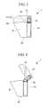
- FIGs. 5 and 6 show another form of the intake-air cooling apparatus 1 according to this embodiment.
- This intake-air cooling apparatus 1 has notches (cuts) 63 under the case 51 and at the front parts of side plates 61 that constitute both sides of the outside-air duct 49.
- the strength around the notches 63 is lower than that of the other parts.
- This embodiment is similar to the first embodiment in basic structure but different in the structure of the intake-air cooling apparatus 1. Thus, in this embodiment, only the difference will be described, and duplicated descriptions of the other parts will be omitted.
- Fig. 7 is a side view showing the schematic front structure of the automobile 3 equipped with the intake-air cooling apparatus 1.
- Fig. 8 is a perspective view showing the overall schematic structure of the intake-air cooling apparatus 1.
- the intake-air cooling apparatus 1 is disposed under the hood 9.
- the hood 9 is provided with an outside-air duct 50 having an opening and guiding outside air to the intercooler 41 and the outside-air duct 49 that guides the outside air from the intercooler 41 into the engine compartment 5.
- the outside-air ducts 49 and 50 are configured to introduce outside air substantially vertically. As shown in Figs. 7 and 8 , the intercooler 41 is inclined along the inclination of the hood 9; that is, it rests substantially horizontally.
- a front plate (one wall) 65 of the case 51 constitutes the back of the outside-air duct 49.
- the case 51 and the outside-air duct 49 are fixed together.
- the intercooler 41 and the evaporator 43 are integrated into a single structure via the outside-air duct 49 and the case 51.
- the intercooler 41 and the evaporator 43 can be disposed compactly.
- the evaporator 43 is disposed at an angle so as to rise forward in substantially a midpoint position of the case 51 in the front-to-back direction to partition the interior of the case 51 into two spaces, the front and rear spaces.
- the intake air cooled by outside air through the intercooler 41 is introduced into the front space of the case 51 through the pipe duct 55.
- the introduced intake air is cooled by the evaporator 43 when moving into the rear space through the evaporator 43.
- the cooled intake air is supplied to the gasoline engine 15 through the pipe duct 57.
- the inlet of the intake air to the case 51 is located at the front plate 65 as described above, the intake air flows out from the rear space.
- This embodiment is similar to the first embodiment in basic structure but different in the structure of the intake-air cooling apparatus 1. Thus, in this embodiment, only the difference will be described, and duplicated descriptions of the other parts will be omitted.
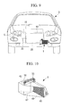
- Fig. 9 is a front view showing the schematic front structure of the automobile 3 equipped with the intake-air cooling apparatus 1.
- Fig. 10 is a perspective view showing the overall schematic structure of the intake-air cooling apparatus 1.
- Fig. 11 is a plan view of the intake-air cooling apparatus 1.
- the intake-air cooling apparatus 1 is disposed in front of the condenser 25. This position provides space at one side, so that the case 51 is disposed at one side of the intercooler 41.
- a side plate (one wall) 67 of the case 51 constitutes one side of the outside-air duct 49.
- the case 51 and the outside-air duct 49 are fixed together.
- the intercooler 41 and the evaporator 43 are integrated into a single structure via the outside-air duct 49 and the case 51.
- the intercooler 41 and the evaporator 43 can be disposed compactly.
- the evaporator 43 is disposed in substantially a midpoint position of the case 51 in the front-to-back direction such that the surfaces extend substantially vertically and rotate in a horizontal plane to partition the interior of the case 51 into two spaces, a distal space and a proximal space.
- the intake air cooled by the outside air passing through the intercooler 41 is introduced into the near space in the case 51 via the pipe duct 55. This introduced intake air is cooled by the evaporator 43 while moving into the remote space via the evaporator 43.
- This cooled intake air is supplied to the gasoline engine 15 through the pipe duct 57.
- the inlet of the intake air to the case 51 is located at the side plate 67 as described above, the intake air flows out from the remote space.
- This embodiment is similar to the first embodiment (and the second embodiment) in basic structure but different in the structure of the intake-air cooling apparatus 1. Thus, in this embodiment, only the difference will be described, and duplicated descriptions of the other parts will be omitted.
- Fig. 12 is a side view showing the schematic front structure of the automobile 3 equipped with the intake-air cooling apparatus 1.
- Fig. 13 is a perspective view showing the overall schematic structure of the intake-air cooling apparatus 1.
- the intake-air cooling apparatus 1 is disposed at the rearmost part of the engine compartment 5.
- the structure of the intake-air cooling apparatus 1 is substantially the same as that of the second embodiment. However, since the rear of the case 51 protrudes into the vehicle cabin 7, the intake-air cooling apparatus 1 is decreased in length in the front-to-back direction and increased in length correspondingly in the vertical direction to decrease the protrusion.
- the evaporator 43 is set up so as to extend as far vertically as possible from the bottom of the intercooler 41 to the bottom of the outside-air duct 49.
- the front plate 65 of the case 51 constitutes the back of the outside-air duct 49.
- the case 51 and the outside-air duct 49 are fixed together.
- the outside-air duct 49 is longer in the vertical direction than that of the second embodiment.
- the intercooler 41 is located at the rearmost part of the hood 9. This structure in which the case 51 is vertically long is also for the purpose of decreasing the protrusion of the case 51 into the vehicle cabin 7.
- This part has the highest negative pressure, so that a large quantity of outside air is allowed to flow in merely by forming a grille 69 in the hood 9. This remarkably improves the cooling efficiency.
Landscapes
- Engineering & Computer Science (AREA)
- Mechanical Engineering (AREA)
- General Engineering & Computer Science (AREA)
- Chemical & Material Sciences (AREA)
- Combustion & Propulsion (AREA)
- Physics & Mathematics (AREA)
- Thermal Sciences (AREA)
- Cooling, Air Intake And Gas Exhaust, And Fuel Tank Arrangements In Propulsion Units (AREA)
- Heat-Exchange Devices With Radiators And Conduit Assemblies (AREA)
Applications Claiming Priority (1)
| Application Number | Priority Date | Filing Date | Title |
|---|---|---|---|
| JP2007316159A JP2009138635A (ja) | 2007-12-06 | 2007-12-06 | 内燃機関の吸気冷却装置およびこれを用いた自動車 |
Publications (2)
| Publication Number | Publication Date |
|---|---|
| EP2067955A2 true EP2067955A2 (fr) | 2009-06-10 |
| EP2067955A3 EP2067955A3 (fr) | 2013-02-13 |
Family
ID=40419133
Family Applications (1)
| Application Number | Title | Priority Date | Filing Date |
|---|---|---|---|
| EP08167789A Withdrawn EP2067955A3 (fr) | 2007-12-06 | 2008-10-29 | Appareil de refroidissement d'air d'admission pour moteur à combustion interne et automobile l'utilisant |
Country Status (3)
| Country | Link |
|---|---|
| US (1) | US20090145409A1 (fr) |
| EP (1) | EP2067955A3 (fr) |
| JP (1) | JP2009138635A (fr) |
Cited By (1)
| Publication number | Priority date | Publication date | Assignee | Title |
|---|---|---|---|---|
| EP2628896A3 (fr) * | 2012-02-14 | 2014-03-12 | Behr GmbH & Co. KG | Dispositif de transfert de chaleur |
Families Citing this family (11)
| Publication number | Priority date | Publication date | Assignee | Title |
|---|---|---|---|---|
| DE102007024631A1 (de) * | 2007-05-24 | 2008-11-27 | Behr Gmbh & Co. Kg | Integriertes Auflademodul |
| JP5704440B2 (ja) * | 2010-12-27 | 2015-04-22 | スズキ株式会社 | 車両用インタークーラの冷却装置 |
| TWI500850B (zh) * | 2012-09-28 | 2015-09-21 | Chi Hsu Tsai | 噴射引擎之降溫方法及其降溫裝置 |
| US20160222833A1 (en) * | 2015-02-03 | 2016-08-04 | Borgwarner Inc. | Waste heat recovery system layout and packaging strategy |
| US10006339B2 (en) * | 2016-01-26 | 2018-06-26 | Fca Us Llc | Chiller system for an engine with a forced induction system |
| KR101704340B1 (ko) * | 2016-03-03 | 2017-02-07 | 현대자동차주식회사 | 에어컨 시스템과 통합된 하이브리드형 인터쿨러 시스템 및 그 제어방법 |
| US10830122B2 (en) | 2018-10-29 | 2020-11-10 | Fca Us Llc | Intake and charge air cooling system |
| FR3100484B1 (fr) * | 2019-09-10 | 2022-05-20 | Valeo Systemes Thermiques | Module de refroidissement pour véhicule automobile à turbomachine tangentielle |
| JP2023017583A (ja) * | 2021-07-26 | 2023-02-07 | マツダ株式会社 | エンジンの吸気システム |
| US11680515B1 (en) | 2022-03-31 | 2023-06-20 | Fca Us Llc | Intake and charge air cooling system with passive variable charge enabler |
| WO2024259072A1 (fr) * | 2023-06-16 | 2024-12-19 | Woolf Dustin | Refroidisseur intermédiaire de moteur à combustion interne avec système de réfrigération intégré |
Citations (1)
| Publication number | Priority date | Publication date | Assignee | Title |
|---|---|---|---|---|
| JPS59146531U (ja) | 1983-12-28 | 1984-09-29 | ダイキン工業株式会社 | 過給機付エンジンの吸入空気冷却装置 |
Family Cites Families (5)
| Publication number | Priority date | Publication date | Assignee | Title |
|---|---|---|---|---|
| US2359219A (en) * | 1943-03-26 | 1944-09-26 | Green S Fuel Inc | Means for using liquefied petroleum gases for engine fuel |
| JPS6093116A (ja) * | 1983-10-26 | 1985-05-24 | Nissan Motor Co Ltd | 蒸発冷却式インタ−ク−ラ装置 |
| JPS6165014A (ja) * | 1984-09-04 | 1986-04-03 | Mazda Motor Corp | 過給機付エンジンの吸気装置 |
| JPS6346627U (fr) * | 1986-09-11 | 1988-03-29 | ||
| US6932148B1 (en) * | 2002-10-07 | 2005-08-23 | Scs Frigette | Vehicle heating and cooling system |
-
2007
- 2007-12-06 JP JP2007316159A patent/JP2009138635A/ja not_active Withdrawn
-
2008
- 2008-10-23 US US12/289,228 patent/US20090145409A1/en not_active Abandoned
- 2008-10-29 EP EP08167789A patent/EP2067955A3/fr not_active Withdrawn
Patent Citations (1)
| Publication number | Priority date | Publication date | Assignee | Title |
|---|---|---|---|---|
| JPS59146531U (ja) | 1983-12-28 | 1984-09-29 | ダイキン工業株式会社 | 過給機付エンジンの吸入空気冷却装置 |
Cited By (1)
| Publication number | Priority date | Publication date | Assignee | Title |
|---|---|---|---|---|
| EP2628896A3 (fr) * | 2012-02-14 | 2014-03-12 | Behr GmbH & Co. KG | Dispositif de transfert de chaleur |
Also Published As
| Publication number | Publication date |
|---|---|
| JP2009138635A (ja) | 2009-06-25 |
| US20090145409A1 (en) | 2009-06-11 |
| EP2067955A3 (fr) | 2013-02-13 |
Similar Documents
| Publication | Publication Date | Title |
|---|---|---|
| EP2067955A2 (fr) | Appareil de refroidissement d'air d'admission pour moteur à combustion interne et automobile l'utilisant | |
| CN101263285B (zh) | 用于汽车的冷却系统 | |
| US9551273B2 (en) | Charge air cooling system | |
| US6957689B2 (en) | Heat exchanger arrangement particularly for motor vehicle | |
| US8602093B2 (en) | Composite heat exchanger and composite heat exchanger system | |
| RU137338U1 (ru) | Впускной узел в двигателе (варианты) | |
| US9488134B2 (en) | Engine system having turbo charger | |
| US20080087402A1 (en) | Apparatus for cooling charge air for a combustion engine, system with an apparatus for cooling charge air | |
| US20100006043A1 (en) | Cooling arrangement at a vehicle | |
| JP2011503436A (ja) | 過給燃焼機関の構成 | |
| KR20050021507A (ko) | 증압된 분사시스템의 복귀 라인내 연료냉각장치 | |
| US9261056B2 (en) | Intake enhancement system for a vehicle | |
| CN113650474B (zh) | Hev混合动力汽车整车热管理系统及控制方法 | |
| US8112993B2 (en) | Arrangement of a charge air cooler in an intake system of an internal combustion engine | |
| EP1886012A1 (fr) | Dispositif pour la recirculation de gaz d echappement d un moteur a combustion interne suralimente | |
| US7748437B2 (en) | Heat exchanger with tube core, in particular for a supercharged internal combustion engine | |
| EP4026718B1 (fr) | Dispositif d'échange de chaleur pour véhicules | |
| EP2564043A1 (fr) | Agencement permettant de refroidir de l'air comprimé et/ou des gaz d'échappement recyclés qui sont amenés jusqu'à un moteur à combustion | |
| US20050013704A1 (en) | Cooling air inlet arrangement | |
| US9186953B2 (en) | Intake enhancement system for vehicle | |
| US6837194B2 (en) | Motor vehicle cooling system and motor vehicle embodying same | |
| JP2012245866A (ja) | 複合熱交換器 | |
| WO2020183214A1 (fr) | Dispositif d'échange de chaleur pour véhicules | |
| KR20040043523A (ko) | 차량의 흡입 공기 냉각장치 |
Legal Events
| Date | Code | Title | Description |
|---|---|---|---|
| PUAI | Public reference made under article 153(3) epc to a published international application that has entered the european phase |
Free format text: ORIGINAL CODE: 0009012 |
|
| AK | Designated contracting states |
Kind code of ref document: A2 Designated state(s): AT BE BG CH CY CZ DE DK EE ES FI FR GB GR HR HU IE IS IT LI LT LU LV MC MT NL NO PL PT RO SE SI SK TR |
|
| AX | Request for extension of the european patent |
Extension state: AL BA MK RS |
|
| PUAL | Search report despatched |
Free format text: ORIGINAL CODE: 0009013 |
|
| AK | Designated contracting states |
Kind code of ref document: A3 Designated state(s): AT BE BG CH CY CZ DE DK EE ES FI FR GB GR HR HU IE IS IT LI LT LU LV MC MT NL NO PL PT RO SE SI SK TR |
|
| AX | Request for extension of the european patent |
Extension state: AL BA MK RS |
|
| RIC1 | Information provided on ipc code assigned before grant |
Ipc: F28D 1/04 20060101ALI20130109BHEP Ipc: F02M 35/16 20060101ALI20130109BHEP Ipc: B60H 1/00 20060101ALI20130109BHEP Ipc: F02B 29/04 20060101AFI20130109BHEP |
|
| STAA | Information on the status of an ep patent application or granted ep patent |
Free format text: STATUS: THE APPLICATION IS DEEMED TO BE WITHDRAWN |
|
| AKY | No designation fees paid | ||
| 18D | Application deemed to be withdrawn |
Effective date: 20130503 |
|
| REG | Reference to a national code |
Ref country code: DE Ref legal event code: R108 Effective date: 20131016 |