EP2068219A2 - Jouet robot et son procédé de montage - Google Patents
Jouet robot et son procédé de montage Download PDFInfo
- Publication number
- EP2068219A2 EP2068219A2 EP08170467A EP08170467A EP2068219A2 EP 2068219 A2 EP2068219 A2 EP 2068219A2 EP 08170467 A EP08170467 A EP 08170467A EP 08170467 A EP08170467 A EP 08170467A EP 2068219 A2 EP2068219 A2 EP 2068219A2
- Authority
- EP
- European Patent Office
- Prior art keywords
- servo
- rotating disk
- block
- output shaft
- robot toy
- Prior art date
- Legal status (The legal status is an assumption and is not a legal conclusion. Google has not performed a legal analysis and makes no representation as to the accuracy of the status listed.)
- Withdrawn
Links
Images


Classifications
-
- G—PHYSICS
- G05—CONTROLLING; REGULATING
- G05B—CONTROL OR REGULATING SYSTEMS IN GENERAL; FUNCTIONAL ELEMENTS OF SUCH SYSTEMS; MONITORING OR TESTING ARRANGEMENTS FOR SUCH SYSTEMS OR ELEMENTS
- G05B19/00—Program-control systems
- G05B19/02—Program-control systems electric
- G05B19/418—Total factory control, i.e. centrally controlling a plurality of machines, e.g. direct or distributed numerical control [DNC], flexible manufacturing systems [FMS], integrated manufacturing systems [IMS] or computer integrated manufacturing [CIM]
- G05B19/41805—Total factory control, i.e. centrally controlling a plurality of machines, e.g. direct or distributed numerical control [DNC], flexible manufacturing systems [FMS], integrated manufacturing systems [IMS] or computer integrated manufacturing [CIM] characterised by assembly
-
- B—PERFORMING OPERATIONS; TRANSPORTING
- B25—HAND TOOLS; PORTABLE POWER-DRIVEN TOOLS; MANIPULATORS
- B25J—MANIPULATORS; CHAMBERS PROVIDED WITH MANIPULATION DEVICES
- B25J9/00—Program-controlled manipulators
- B25J9/06—Program-controlled manipulators characterised by multi-articulated arms
-
- B—PERFORMING OPERATIONS; TRANSPORTING
- B25—HAND TOOLS; PORTABLE POWER-DRIVEN TOOLS; MANIPULATORS
- B25J—MANIPULATORS; CHAMBERS PROVIDED WITH MANIPULATION DEVICES
- B25J19/00—Accessories fitted to manipulators, e.g. for monitoring, for viewing; Safety devices combined with or specially adapted for use in connection with manipulators
- B25J19/02—Sensing devices
-
- B—PERFORMING OPERATIONS; TRANSPORTING
- B25—HAND TOOLS; PORTABLE POWER-DRIVEN TOOLS; MANIPULATORS
- B25J—MANIPULATORS; CHAMBERS PROVIDED WITH MANIPULATION DEVICES
- B25J9/00—Program-controlled manipulators
- B25J9/16—Program controls
- B25J9/1615—Program controls characterised by special kind of manipulator, e.g. planar, scara, gantry, cantilever, space, closed chain, passive/active joints and tendon driven manipulators
-
- Y—GENERAL TAGGING OF NEW TECHNOLOGICAL DEVELOPMENTS; GENERAL TAGGING OF CROSS-SECTIONAL TECHNOLOGIES SPANNING OVER SEVERAL SECTIONS OF THE IPC; TECHNICAL SUBJECTS COVERED BY FORMER USPC CROSS-REFERENCE ART COLLECTIONS [XRACs] AND DIGESTS
- Y02—TECHNOLOGIES OR APPLICATIONS FOR MITIGATION OR ADAPTATION AGAINST CLIMATE CHANGE
- Y02P—CLIMATE CHANGE MITIGATION TECHNOLOGIES IN THE PRODUCTION OR PROCESSING OF GOODS
- Y02P90/00—Enabling technologies with a potential contribution to greenhouse gas [GHG] emissions mitigation
- Y02P90/02—Total factory control, e.g. smart factories, flexible manufacturing systems [FMS] or integrated manufacturing systems [IMS]
-
- Y—GENERAL TAGGING OF NEW TECHNOLOGICAL DEVELOPMENTS; GENERAL TAGGING OF CROSS-SECTIONAL TECHNOLOGIES SPANNING OVER SEVERAL SECTIONS OF THE IPC; TECHNICAL SUBJECTS COVERED BY FORMER USPC CROSS-REFERENCE ART COLLECTIONS [XRACs] AND DIGESTS
- Y10—TECHNICAL SUBJECTS COVERED BY FORMER USPC
- Y10T—TECHNICAL SUBJECTS COVERED BY FORMER US CLASSIFICATION
- Y10T29/00—Metal working
- Y10T29/49—Method of mechanical manufacture
- Y10T29/49826—Assembling or joining
Definitions
- the present invention relates to a robot toy and an assembling method of the robot toy, and in particular, a robot toy including a servo and an assembling method of the robot toy.
- a robot toy with a structure of connecting one block and another block with a servo is known.
- a leg of a humanoid robot toy is described.
- components of the leg include one block mounted with an RC turbo thereon and the other block to be connected to the one block.
- an initial voltage is placed on a signal line of a servo to figure out a center position (servo zero position) and an output shaft of the servo is fitted into a boss of the other block at a home position (basic starting position) of the one block and the other block.
- adjoining blocks are attached together. With this, the entire leg is assembled.
- a spline is usually provided in the output shaft of the servo.
- the spline of the output shaft and a concave section of an inner circumference of the boss need to be meshed.
- a control IC in the robot toy is connected to a personal computer so that the servo zero position and the home position is matched with an editor.
- Such a situation may occur when there is an error in design of the components of the robot toy.
- the present invention has been made in consideration of the above problems.
- the present invention seeks to provide a robot toy and an assembling method thereof to easily match a home position and a servo zero position of a robot toy.
- a robot toy comprising:
- one block is connected to the other block through a servo
- the servo is provided with a first rotating disk rotating following the output shaft, a second rotating disk provided facing the first rotating disk to rotate relatively to the first rotating disk in a plane parallel to the first rotating disk according to user operation, and an angle detection section to detect a relative angle between predetermined reference lines of the first rotating disk and the second rotating disk
- the servo control section includes a center position control section to rotate the output shaft and the first rotating disk and to control the servo while the position of the servo when the relative angle is 0 is a center position, therefore, the center position of the servo can be matched to the home position by judging whether or not the positional relation of the one block and the other block matches the home position after the center position of the servo is output by the servo control section, and by repeating steps of rotating the second rotating disk relatively to the first rotating disk when it is judged the positional relation does not match the home position, and allowing the servo control section to output the
- the angle detection section includes variable resistance circuits provided on faces of the first rotating disk and the second rotating disk facing each other, and resistance values of the variable resistance circuits change according to the relative angle.
- the second rotating disk includes a lever protruding outward than a case of the servo and the second rotating disk rotates relatively to the first rotating disk by user operation of the lever.
- the second rotating disk suitably includes a lever protruding outward than the case of the servo, and the second rotating disk rotates relatively to the first rotating disk by user operation of the lever, therefore, the second rotating disk can be rotated without removing the case of the servo. Consequently, the home position and the servo zero position of the robot toy can be matched more easily.
- an assembling method of a robot toy to assemble a robot toy of the first aspect of the present invention comprising the successive steps of:
- the method repeats rotation angle adjusting step where the second rotating disk rotates relatively to the first rotating disk, the center position outputting step and the judging step, and when the judging step judges the positional relation matches the home position, connecting of the one block and the other block ends, therefore, the robot toy can be assembled with the center position of the servo matching to the home position. Consequently, the robot toy can be assembled easily matching the home position and the servo zero position of the robot toy.
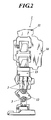
- FIG. 1 is an elevation view showing a robot toy 1 of the present embodiment and FIG. 2 is a right side view showing a robot toy 1.
- the robot toy 1 includes a torso section 10, head section 11, leg section 12, and arm section 13 and joint portions of the leg section 12 and arm section 13 each include a servo 3 driven according to operation of the controller.
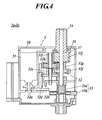
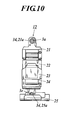
- the servo 3 is driven to rotate the output shaft 34 and inside a case 30, includes a servo motor 31, reduction gear mechanism 32 and potentiometer 33.
- the servo motor 31 rotates the reduction gear mechanism 32.
- the reduction gear mechanism 32 includes gears 32a to 32j and the power output from the servo motor 31 transfers in the order of the gears 32a to 32j to rotate the output shaft 34.
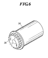
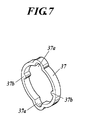
- a clutch mechanism 35 is built between the final gear 32j of the reduction gear mechanism 32 and the output shaft 34, and the gear 32j and the output shaft 34 are structured so that they can rotate independently of each other. More specifically, as shown in FIG. 5 , two half cylinder shaped projections 32j-1 and 32j-1 are provided on an end face of the gear 32j. On the other hand, as shown in FIG. 6 , a gear 36 is provided on the end face of the output shaft 34. The gear 32j and the gear 36 are connected to each other through a clutch member 37 as shown in FIG. 7 .
- the clutch member 37 is ring-shaped and two concave sections 37a and 37a to engage with the two half cylinder shaped projections 32j-1 and 32j-1 and two convex sections 37b and 37b to mesh with teeth of the gear 36 are formed on the inner circumference of the clutch member 37.
- the gears 32g and 32j are formed in a ring shape, and a central shaft (not shown) of the output shaft 34 is inserted through the gears 32g and 32j so that a tip is integrated with a later-described rotating disk 33a.
- a central shaft (not shown) of the output shaft 34 is inserted through the gears 32g and 32j so that a tip is integrated with a later-described rotating disk 33a.
- splines 34a stretching in a shaft direction are provided with predetermined spacing, however the splines 34a do not have to be provided.
- the potentiometer 33 detects a rotation angle of the servo motor 31, and as shown in FIG. 4 and FIG. 8 , includes rotating disks 33a and 33b.
- the rotating disk (first rotating disk) 33a is a disk shaped member provided at the tip of the above-described central shaft of the output shaft 34 and rotates together with the output shaft 34.
- the rotating disk (second rotating disk) 33b is a plate-shaped member supported by the case 30 and includes a lever 330 protruding outward from the case 30. The lever 330 allows the rotating disk 33b to rotate in a plane parallel to the rotating disk 33a and to rotate around a shaft line of the output axis 34 by user operation.
- the angular range in which the rotating disk 33b can rotate is about 15 degrees.
- predetermined center lines in the rotating disks 33a and 33b are described as reference lines 33c and 33d.
- circuit patterns 8 and 9 are provided on faces of the rotating disks 33a and 33b opposing to each other.
- the circuit patterns 8 and 9 are formed from conductive material such as carbon, and when the rotating disks 33a and 33b relatively rotate, resistance value changes according to the relative angle between the reference lines 33c and 33d.
- the circuit pattern 8 provided on the rotating disk 33a include circular shaped circular circuit section 81 and center line circuit section 82 which passes through the center of the circular circuit section 81 on the reference line 33c to connect two points on the circumference.
- a terminal 83 is provided on a middle point of the center line circuit section 82, that is, center of the circular circuit section 81 and a terminal 84 is provided on the intersection point of circular circuit section 81 and center line circuit section 82.
- the circuit pattern 9 provided on the rotating disk 33b includes a central circuit section 91 stretching on the reference line 33d from a position touching the terminal 83 to an end portion opposing to the lever 330, and an arc-shaped circuit section 92 facing the circular circuit section 81.
- One electrode between a positive electrode or negative electrode of a battery (not shown) is connected to an electrode 91a of an end portion of the central circuit section 91 and the other electrode is connected to electrodes 92a and 92b of an end portion of the arc-shaped circuit section 92.
- the resistance value between the electrodes 91a and 92a and the resistance value between the electrodes 91a and 92b differ by the amount of the relative angle, in other words, by the difference between lengths of the paths from the terminal 84 to the end portions of the electrodes 92a and 92b, and as a result, the rotation angle of the output shaft 34 of the servo motor 31 is detected as the difference of analog electric current.
- a battery (not shown), a control device 100 and receiving circuit 110 are connected to each other.
- the battery, control device 100 and receiving circuit 110 are included in the torso section 10 of the robot toy 1.
- the control device 100 processes signals and the like from the receiving circuit 110 and potentiometer 33 and controls operation of the servo motor 31 by digital signals. For example, when power of the robot toy 1 is turned on, the control device 100 applies an initial pulse to the servo motor 31 according to a signal from the potentiometer 33 to move the servo 3 to the center position (servo zero position).
- the center position of the servo 3 is a position where, in the potentiometer 33, electric current between the electrodes 91a and 92a and electric current between the electrodes 91a and 92b are equal, in other words, a position where the relative angle is 0.
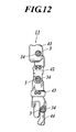
- the leg section 12 includes broadly five blocks 21, 22, 23, 24 and 25.
- block 21 is connected to the torso section (block) 10 through the servo 3 (hereinafter referred to as servo 3a, in order to distinguish from other servos 3).
- the block 21 is connected to the torso section 10 by fitting the output shaft 34 of the servo 3a provided at the bottom edge portion of the torso section 10 into a boss 21a.
- a concave section (not shown) meshing with the spline 34a of the output shaft 34 is provided on the inner circumference face of the above-described boss 21a and later-described bosses 22a to 25b.
- the servo 3 (hereinafter referred to as servo 3b in order to distinguish from other servos 3) is provided on the bottom edge portion of the block 21 and the block 22 are connected through the servo 3b.
- the block 22 is connected to the block 21 by fitting the output shaft 34 of the servo 3b into the boss 22a. With this, when the servo motor 31 of the servo 3b is driven to rotate, the block 22 moves with respect to the block 21.
- the servo 3 (hereinafter referred to as servo 3c in order to distinguish from other servos 3) is provided on the bottom edge portion of the block 22 and the block 23 are connected through the servo 3c.
- the block 23 is connected to the block 22 by fitting the output shaft 34 of the servo 3c into the boss 23a. With this, when the servo motor 31 of the servo 3c is driven to rotate, the block 23 moves with respect to the block 22.
- the servo 3 (hereinafter referred to as servo 3d in order to distinguish from other servos 3) is provided on the bottom edge portion of the block 23 and the block 24 are connected through the servo 3d.
- the block 24 is connected to the block 23 by fitting the output shaft 34 of the servo 3d into the boss 24a. With this, when the servo motor 31 of the servo 3d is driven to rotate, the block 24 moves with respect to the block 23.
- the servo 3 (hereinafter referred to as servo 3e in order to distinguish from other servos 3) is provided on the bottom edge portion of the block 24 and the block 25 are connected through the servo 3e.
- the block 25 is connected to the block 24 by fitting the output shaft 34 of the servo 3e into the boss 25a. With this, when the servo motor 31 of the servo 3e is driven to rotate, the block 25 moves with respect to the block 24.
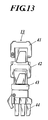
- the arm section 13 includes broadly five blocks 41, 42, 43, 44 and 45. These blocks 41, 42, 43, 44 and 45 are connected through the servos 3 from the torso section 10 in this order.
- a connection structure of the torso section (block) 10 and block 41 can be the same as a connection structure of the blocks connected to each other in the arm section 13 or the block 41 can be fixed to the torso section 10.
- leg section 12 As an example.
- the control device 100 energizes the servo motor 31 of the servo 3a to output the center position (servo zero position) of the servo 3a, in other words, the position where current between the electrodes 91a and 92a and current between the electrodes 91a and 92b are equal on the potentiometer 33 (center position output process).
- an angle between the torso section 10 and block 21 is an angle of home position (judging process) and when it is judged that the angle between the torso section 10 and block 21 is not the angle of home position, a rotating process of the rotating disk 33b through the lever 330 of the servo 3a (rotation angle adjustment process) and the above-described center position output process and judging process are repeated.
- the above-described judging process can judge whether or not the angle between the torso section 10 and block 21 is the angle of the home position visually or judging can be done using a template previously formed in the angle of the home position.
- adjacent blocks of the leg section 12 are connected to each other and adjacent blocks of the arm section 13 are connected to each other and the assembly of the robot 1 ends.
- the robot toy 1 it is judged whether or not a positional relation of the one block (for example, block 10) and the other block (for example, block 21) matches the home position after the center position of the servo 3 is output, and by repeating a process of rotating the rotating disk 33b relatively to the rotating disk 33a when it is judged that the positional relation does not match the home position, and allowing the servo 3 to output the center position again to judge whether or not the positional relation matches the home position, the center position of the servo 3 can be matched with the home position. Therefore, since the servo zero position and home position can be matched without connecting the servo 3 to a personal computer and operating an editor, compared to the conventional method, the home position and the servo zero position of the robot toy 1 can be easily matched.
- the rotating disk 33b includes a lever 330 protruding outward than the case 30 of the servo 3, the rotating disk 33b rotates relatively to the rotating disk 33a by the user operation of the lever 330, therefore, the rotating disk 33b can be rotated without removing the case 30 of the servo 3. Therefore, it is easier to match the home position and the servo zero position of the robot toy 1.
- variable resistance circuits of the present invention are described as circuit pattern 8 and 9 in a shape shown in FIG. 8 , however, the circuit can be another shape.
Landscapes
- Engineering & Computer Science (AREA)
- Robotics (AREA)
- Mechanical Engineering (AREA)
- Health & Medical Sciences (AREA)
- General Health & Medical Sciences (AREA)
- Orthopedic Medicine & Surgery (AREA)
- General Engineering & Computer Science (AREA)
- Manufacturing & Machinery (AREA)
- Quality & Reliability (AREA)
- Physics & Mathematics (AREA)
- General Physics & Mathematics (AREA)
- Automation & Control Theory (AREA)
- Toys (AREA)
- Manipulator (AREA)
Applications Claiming Priority (1)
| Application Number | Priority Date | Filing Date | Title |
|---|---|---|---|
| JP2007317402A JP4397412B2 (ja) | 2007-12-07 | 2007-12-07 | ロボット玩具およびその組立方法 |
Publications (1)
| Publication Number | Publication Date |
|---|---|
| EP2068219A2 true EP2068219A2 (fr) | 2009-06-10 |
Family
ID=40499307
Family Applications (1)
| Application Number | Title | Priority Date | Filing Date |
|---|---|---|---|
| EP08170467A Withdrawn EP2068219A2 (fr) | 2007-12-07 | 2008-12-02 | Jouet robot et son procédé de montage |
Country Status (6)
| Country | Link |
|---|---|
| US (1) | US7905760B2 (fr) |
| EP (1) | EP2068219A2 (fr) |
| JP (1) | JP4397412B2 (fr) |
| KR (1) | KR20090060150A (fr) |
| CN (1) | CN101450259A (fr) |
| TW (1) | TW200938284A (fr) |
Families Citing this family (12)
| Publication number | Priority date | Publication date | Assignee | Title |
|---|---|---|---|---|
| KR20150100165A (ko) * | 2014-02-24 | 2015-09-02 | 주식회사 로보빌더 | 모듈러 액츄에이터 결합장치 |
| WO2015151161A1 (fr) * | 2014-03-31 | 2015-10-08 | 株式会社アーテック | Bloc d'assemblage à servomoteur, et kit de bloc d'assemblage |
| US9592603B2 (en) * | 2014-12-01 | 2017-03-14 | Spin Master Ltd. | Reconfigurable robotic system |
| KR101786447B1 (ko) * | 2016-05-23 | 2017-11-15 | (주)엠알티인터내셔널 | 색상제어가능 서보모터모듈 및 이를 적용한 다관절 휴머노이드 로봇 |
| KR101784146B1 (ko) * | 2016-05-23 | 2017-10-11 | (주)엠알티인터내셔널 | 슈트교체가능 다관절 휴머노이드 로봇 |
| CN106113037A (zh) * | 2016-06-30 | 2016-11-16 | 张春生 | 一种智能儿童玩具组装模块机器人的面感知模块 |
| WO2018009722A1 (fr) | 2016-07-06 | 2018-01-11 | Michael Bellon | Figurine d'action |
| US11025132B2 (en) * | 2018-01-16 | 2021-06-01 | 2576150 Ontario Corp. | Case for a servomotor |
| CN109015751B (zh) * | 2018-07-12 | 2023-12-29 | 深圳市优必选科技有限公司 | 机器人及其舵机、过载保护结构 |
| CN109011651B (zh) * | 2018-07-25 | 2020-06-09 | 上海葡萄纬度科技有限公司 | 一种交互式玩具 |
| JP6707701B1 (ja) * | 2019-09-03 | 2020-06-10 | 株式会社タカラトミー | アクションロボット玩具 |
| US12303799B2 (en) * | 2023-08-18 | 2025-05-20 | Zeluan Cai | Assembled robot toy |
Family Cites Families (22)
| Publication number | Priority date | Publication date | Assignee | Title |
|---|---|---|---|---|
| US3547240A (en) * | 1968-09-19 | 1970-12-15 | Frank Holper | Clutch means for selectively coupling a single input to one or more plural outputs |
| US5155423A (en) * | 1986-02-18 | 1992-10-13 | Robotics Research Corporation | Industrial robot with servo |
| JP2602815B2 (ja) * | 1986-08-08 | 1997-04-23 | 株式会社東芝 | 関節装置 |
| JPH061193Y2 (ja) | 1987-09-14 | 1994-01-12 | 精工研株式会社 | ゼンマイ式動力装置用双方向クラッチ |
| JPH0377754A (ja) | 1989-08-18 | 1991-04-03 | Kawasaki Steel Corp | 連鋳鋳型内に注入される溶鋼の偏流防止方法 |
| US5280981A (en) * | 1991-02-01 | 1994-01-25 | Odetics, Inc. | End effector with load-sensitive digit actuation mechanisms |
| US5158493A (en) * | 1991-05-30 | 1992-10-27 | Richard Morgrey | Remote controlled, multi-legged, walking robot |
| US5318471A (en) * | 1991-12-06 | 1994-06-07 | Glovier Lloyd H | Robotic joint movement device |
| JPH09193059A (ja) | 1996-01-17 | 1997-07-29 | Canon Inc | ロボットの原点位置較正方法、その原点位置較正装置、較正用治具およびロボットのアーム位置決め装置 |
| US6902048B1 (en) * | 1999-04-14 | 2005-06-07 | Caleb Chung | Clutch |
| JP2002059388A (ja) | 2000-08-23 | 2002-02-26 | Sony Corp | 回転型アクチュエータおよび回転型アクチュエータを有する歩行ロボット |
| CN1236898C (zh) | 2000-11-17 | 2006-01-18 | 本田技研工业株式会社 | 腿式步行机器人 |
| US6454624B1 (en) * | 2001-08-24 | 2002-09-24 | Xerox Corporation | Robotic toy with posable joints |
| JP3757147B2 (ja) | 2001-10-31 | 2006-03-22 | オムロン株式会社 | ロボットの関節部構造 |
| US6989645B2 (en) * | 2002-12-18 | 2006-01-24 | Sony Corporation | Robot apparatus, and load absorbing apparatus and method |
| KR100578342B1 (ko) | 2003-01-03 | 2006-05-11 | 주식회사 메가로보틱스 | 인공지능형 로봇완구 및 그 제어방법 |
| JP2004255475A (ja) | 2003-02-24 | 2004-09-16 | Oki Electric Ind Co Ltd | サーボ装置 |
| JP4299567B2 (ja) * | 2003-03-31 | 2009-07-22 | 本田技研工業株式会社 | 脚式移動ロボット |
| JP2006035405A (ja) | 2004-07-30 | 2006-02-09 | Sanko Gosei Ltd | ロボット用関節装置 |
| JP4305323B2 (ja) * | 2004-08-11 | 2009-07-29 | ソニー株式会社 | ロボット装置の動作制御装置及び動作制御方法 |
| JP4506512B2 (ja) | 2005-03-07 | 2010-07-21 | トヨタ自動車株式会社 | 支持脚をもつ歩行ロボットのオフセット調整システム及びオフセット調整方法 |
| JP4551893B2 (ja) * | 2006-12-27 | 2010-09-29 | 株式会社タカラトミー | ロボット玩具 |
-
2007
- 2007-12-07 JP JP2007317402A patent/JP4397412B2/ja not_active Expired - Fee Related
-
2008
- 2008-11-25 TW TW097145499A patent/TW200938284A/zh unknown
- 2008-11-28 KR KR1020080119545A patent/KR20090060150A/ko not_active Withdrawn
- 2008-12-02 EP EP08170467A patent/EP2068219A2/fr not_active Withdrawn
- 2008-12-04 US US12/328,457 patent/US7905760B2/en not_active Expired - Fee Related
- 2008-12-05 CN CNA2008101798066A patent/CN101450259A/zh active Pending
Non-Patent Citations (1)
| Title |
|---|
| "Nisoku Hokou Robotto Seisaku Chonyumon", 5 October 2006, OHMSHA, LTD., pages: 140 - 141 |
Also Published As
| Publication number | Publication date |
|---|---|
| CN101450259A (zh) | 2009-06-10 |
| TW200938284A (en) | 2009-09-16 |
| JP2009136570A (ja) | 2009-06-25 |
| US7905760B2 (en) | 2011-03-15 |
| KR20090060150A (ko) | 2009-06-11 |
| JP4397412B2 (ja) | 2010-01-13 |
| US20090149109A1 (en) | 2009-06-11 |
Similar Documents
| Publication | Publication Date | Title |
|---|---|---|
| EP2068219A2 (fr) | Jouet robot et son procédé de montage | |
| EP1938877B1 (fr) | Jouet-robot et son procédé de montage | |
| US6605914B2 (en) | Robotic toy modular system | |
| CN100563767C (zh) | 人工智能机器人玩具及其控制方法 | |
| US20070241714A1 (en) | Robot for surgical applications | |
| KR101722678B1 (ko) | 조립완구 | |
| WO2008015845A1 (fr) | Engrenage et dispositif de liaison utilisant l'engrenage | |
| US20120139468A1 (en) | Multi-rotation hobby servo motors | |
| WO2025059307A1 (fr) | Mécanisme d'actionneur d'embrayage de coupure | |
| HK1131827A (en) | Robot toy and assembling method thereof | |
| EP3470706B1 (fr) | Procédé de développement d'un profil cannelé | |
| JP2002267439A (ja) | 回転角検出器 | |
| CN108454724B (zh) | 具有多种运动模式的双足机器人及其控制方法 | |
| JP4949248B2 (ja) | Cadシステムを用いた歯車の設計方法及び歯車 | |
| EP1616607A1 (fr) | Robot juet d'intelligence artificielle et procédé de commande | |
| JP2020112250A (ja) | ウォーム、および回転機器 | |
| JP5484191B2 (ja) | ギヤードモータの調整方法およびギヤードモータ | |
| JP2017115921A (ja) | ロボット、歯車装置および歯車装置の製造方法 | |
| CN208393510U (zh) | 具有多种运动模式的双足机器人 | |
| CN219617498U (zh) | 一种打磨机控制器调速结构 | |
| JPH0614363Y2 (ja) | ジョイスティックコントローラ | |
| JP5391502B2 (ja) | 回転軸の接続構造およびジョイント部材 | |
| JP2005337745A (ja) | 回転位置検出装置、アクチュエータ装置およびパターン基板 | |
| WO2025079716A1 (fr) | Dispositif rotatif et capteur | |
| Oleynikov et al. | MICROROBOT FOR SURGICAL APPLICATIONS: United States Patent No. US 7,042,184 B2 |
Legal Events
| Date | Code | Title | Description |
|---|---|---|---|
| PUAI | Public reference made under article 153(3) epc to a published international application that has entered the european phase |
Free format text: ORIGINAL CODE: 0009012 |
|
| AK | Designated contracting states |
Kind code of ref document: A2 Designated state(s): AT BE BG CH CY CZ DE DK EE ES FI FR GB GR HR HU IE IS IT LI LT LU LV MC MT NL NO PL PT RO SE SI SK TR |
|
| AX | Request for extension of the european patent |
Extension state: AL BA MK RS |
|
| REG | Reference to a national code |
Ref country code: HK Ref legal event code: DE Ref document number: 1131827 Country of ref document: HK |
|
| STAA | Information on the status of an ep patent application or granted ep patent |
Free format text: STATUS: THE APPLICATION HAS BEEN WITHDRAWN |
|
| 18W | Application withdrawn |
Effective date: 20110113 |
|
| REG | Reference to a national code |
Ref country code: HK Ref legal event code: WD Ref document number: 1131827 Country of ref document: HK |