EP2068403A2 - Connecteur à fiche de cartes conductrices pivotant - Google Patents
Connecteur à fiche de cartes conductrices pivotant Download PDFInfo
- Publication number
- EP2068403A2 EP2068403A2 EP08020415A EP08020415A EP2068403A2 EP 2068403 A2 EP2068403 A2 EP 2068403A2 EP 08020415 A EP08020415 A EP 08020415A EP 08020415 A EP08020415 A EP 08020415A EP 2068403 A2 EP2068403 A2 EP 2068403A2
- Authority
- EP
- European Patent Office
- Prior art keywords
- contact
- printed circuit
- circuit board
- pin
- board connector
- Prior art date
- Legal status (The legal status is an assumption and is not a legal conclusion. Google has not performed a legal analysis and makes no representation as to the accuracy of the status listed.)
- Granted
Links
Images


Classifications
-
- H—ELECTRICITY
- H01—ELECTRIC ELEMENTS
- H01R—ELECTRICALLY-CONDUCTIVE CONNECTIONS; STRUCTURAL ASSOCIATIONS OF A PLURALITY OF MUTUALLY-INSULATED ELECTRICAL CONNECTING ELEMENTS; COUPLING DEVICES; CURRENT COLLECTORS
- H01R13/00—Details of coupling devices of the kinds covered by groups H01R12/70 or H01R24/00 - H01R33/00
- H01R13/62—Means for facilitating engagement or disengagement of coupling parts or for holding them in engagement
- H01R13/629—Additional means for facilitating engagement or disengagement of coupling parts, e.g. aligning or guiding means, levers, gas pressure electrical locking indicators, manufacturing tolerances
- H01R13/631—Additional means for facilitating engagement or disengagement of coupling parts, e.g. aligning or guiding means, levers, gas pressure electrical locking indicators, manufacturing tolerances for engagement only
- H01R13/6315—Additional means for facilitating engagement or disengagement of coupling parts, e.g. aligning or guiding means, levers, gas pressure electrical locking indicators, manufacturing tolerances for engagement only allowing relative movement between coupling parts, e.g. floating connection
-
- H—ELECTRICITY
- H01—ELECTRIC ELEMENTS
- H01R—ELECTRICALLY-CONDUCTIVE CONNECTIONS; STRUCTURAL ASSOCIATIONS OF A PLURALITY OF MUTUALLY-INSULATED ELECTRICAL CONNECTING ELEMENTS; COUPLING DEVICES; CURRENT COLLECTORS
- H01R12/00—Structural associations of a plurality of mutually-insulated electrical connecting elements, specially adapted for printed circuits, e.g. printed circuit boards [PCB], flat or ribbon cables, or like generally planar structures, e.g. terminal strips, terminal blocks; Coupling devices specially adapted for printed circuits, flat or ribbon cables, or like generally planar structures; Terminals specially adapted for contact with, or insertion into, printed circuits, flat or ribbon cables, or like generally planar structures
- H01R12/50—Fixed connections
- H01R12/51—Fixed connections for rigid printed circuits or like structures
- H01R12/52—Fixed connections for rigid printed circuits or like structures connecting to other rigid printed circuits or like structures
-
- H—ELECTRICITY
- H01—ELECTRIC ELEMENTS
- H01R—ELECTRICALLY-CONDUCTIVE CONNECTIONS; STRUCTURAL ASSOCIATIONS OF A PLURALITY OF MUTUALLY-INSULATED ELECTRICAL CONNECTING ELEMENTS; COUPLING DEVICES; CURRENT COLLECTORS
- H01R24/00—Two-part coupling devices, or either of their cooperating parts, characterised by their overall structure
- H01R24/38—Two-part coupling devices, or either of their cooperating parts, characterised by their overall structure having concentrically or coaxially arranged contacts
- H01R24/40—Two-part coupling devices, or either of their cooperating parts, characterised by their overall structure having concentrically or coaxially arranged contacts specially adapted for high frequency
- H01R24/50—Two-part coupling devices, or either of their cooperating parts, characterised by their overall structure having concentrically or coaxially arranged contacts specially adapted for high frequency mounted on a PCB [Printed Circuit Board]
-
- H—ELECTRICITY
- H01—ELECTRIC ELEMENTS
- H01R—ELECTRICALLY-CONDUCTIVE CONNECTIONS; STRUCTURAL ASSOCIATIONS OF A PLURALITY OF MUTUALLY-INSULATED ELECTRICAL CONNECTING ELEMENTS; COUPLING DEVICES; CURRENT COLLECTORS
- H01R2103/00—Two poles
Definitions
- the invention relates to a printed circuit board connector for mounting on printed circuit boards arranged in parallel, wherein at least two plug-in modules designed as a coaxial contact pair are provided, of which one is a pin contact and in the other a socket contact is introduced, wherein the pin or socket contact held centrally in an insulating element is that is surrounded by an electrically conductive sleeve contact.
- Such a device is required in order to contact two printed circuit boards arranged at least approximately parallel to one another, wherein due to the configuration of the contact elements, a skewing or positional offset of the plug-in modules and the printed circuit boards can be bridged to one another within certain limits.
- Such, known coaxial connectors for direct contacting of two circuit boards usually use two identical and rigid contact modules or barrel-shaped spacer elements, and are therefore only partially able to compensate for a shift or a misalignment of individual modules.
- the invention is therefore the object of a device of the type mentioned in such a way that on the one hand to form the coaxial plug-in modules self-catching to compensate for certain positional inaccuracies between two circuit boards and on the other hand, that also slightly different distances between the circuit boards easy and are bridged without special spacer.
- each have a contact holder is arranged with a central opening, within which, spaced from the contact holder, a contact element is fixed with a spherical configuration
- the pin or socket contact in an inner bore has a spherical recess which makes electrical contact with the spherical formation of the contact element
- the electrically conductive sleeve contact has a slot bushing with a concave shaped contact area which contacts a spherical ring formed in the central opening of the contact holder, and that the sleeve contact rotates together with the pin or socket contact by means of the spherical configuration of the contact element around a certain axial area - and is pivotable.
- the Fig. 1a, 1b shows a designed as a pin and a socket contact inner contact of a coaxial plug-in module, which are designed almost identical.
- the mating side of the female contact 20 has a pin-shaped but slotted socket 21, while the pin contact 10 has a closed pin 11.
- the plug-in areas of pin 11 and socket 21 each terminate at a shoulder 12, 22 to which a slotted sleeve part 13, 23 with a plurality of radial projections 14, 24 connects.
- an axial bore 15, 25 is provided with a spherical recess 16, 26, in which later during assembly a spherical formation 41 of a contact element 40 engages.
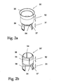
- the Fig. 2a and Fig. 2b show the sleeve contacts 30, 30 'of the coaxially formed printed circuit board connector, which mark the external contact of the coaxial plug-in module. It is in the Fig. 2a the pin contact associated with the sleeve contact 30 and shown in the Fig. 2b the socket contact associated sleeve contact 30 '.
- the two sleeve-shaped body each have an identical slot bushing 31, with which they are rotatably and pivotally held in a contact holder 45, and a plug-in area 32 for contacting with the respective mating connector.
- the sleeve contact 30 has a funnel-shaped contact opening 35, while the sleeve contact 30 'designed as a slot sleeve 33 plug region with four slots 34 here, with an outer circumferential, annular projection 36 for a good contact in the funnel-shaped contact opening 35 of the sleeve contact 30th
- a convex ring 37 is provided which engages in a concave outer groove 52 of an insulating member 50, by means of which the inner pin contact 10 or the female contact 20 within the outer sleeve contact 30, 30' is fixed.
- the slot bushing 31 has a concave outer contact region 38, which allows a certain pivoting movement within the contact holder 45
- the Fig. 3 shows the insulating member 50 of an insulating material, which is circular, formed with a central opening 51. In the wall a concave outer groove 52 is provided.
- the insulating element 50 receives the pin or socket contact 10, 20 in the opening 51 and keeps it insulating from the outer sleeve contact 30, 30 'spaced.
- the contact element 40 is shown for soldering on a printed circuit board 5.
- the contact element 40 establishes the connection between the two inner contacts - pin and socket contact 10, 20 - to the printed circuit board 5, wherein a ball-like Anformung 41 is provided on a disc-shaped foot 42 for contacting with the inner contacts.
- the foot 42 While on the opposite side to the ball-like Anformung 41, the foot 42 has a conical tip 43 for soldering on the circuit board 5.
- the contact element 40 is in the assembly of the plug modules centrally within the opening 47 of the contact holder 45, but spaced therefrom, as in the Fig. 6 is shown.
- the contact holder 45 in Fig. 5a is designed here as a flat, square element, on whose corner sides positioning pins 46 are formed, by means of which primarily the holding forces of the plug-in module are transmitted to the printed circuit board. While a circumferential ring (here between the positioning pins) - a soldering edge 49 - causes a shielding effect of the contact holder 45 for the contact element 40.
- the contact holder 45 has in its central opening 47 an internally encircling, crowned ring 48 which serves for contacting with the inner concave contact region 38 of the sleeve contact 30, 30 '.
- a variant of the contact holder 45 is shown in a central section, which shows a surface-solderable contact holder 45 ', which can be soldered without positioning pins directly by means of Lötkanten 49 on a printed circuit board 5, and the inner region has a concave ring 48'.
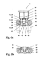
- the Fig. 6a shows an assembled printed circuit board connector in a partially sectioned view.
- a plug-in module 3 is shown, with a pin contact 10, fixed in the insulation element 50, the contact element 40 contacting, and surrounded by the sleeve contact 30 and movably held in the contact holder 45th
- pivoting of the sleeve contact 30 takes place primarily via the spherical recess 16 of the pin contact 10 and the spherical formation 41 of the contact element 40 to be fixed on a printed circuit board.
- Fig. 6b The variant is in the detailed representation of Fig. 6b shown.
- Fig. 5b Here are already in the Fig. 5b indicated structural changes in the external contact between the contact holder 45 'and the slot bush 31' of the sleeve contact 30, 30 'shown.
- the contact region 38 'convex so barrel-shaped and is thus held in the concave ring 48' of the contact holder 45 'movable.
- this contact holder can optionally also have positioning pins.
- Fig. 7a and 7b each show a mounted plug-in module 3 and 3 'with the contact holder 45 and its positioning pins 46, the sleeve contacts 30, 30' and the associated pin and socket contacts 10, 20th
Landscapes
- Coupling Device And Connection With Printed Circuit (AREA)
Applications Claiming Priority (1)
| Application Number | Priority Date | Filing Date | Title |
|---|---|---|---|
| DE102007059254A DE102007059254B3 (de) | 2007-12-08 | 2007-12-08 | Schwenkbarer Leiterkartensteckverbinder |
Publications (3)
| Publication Number | Publication Date |
|---|---|
| EP2068403A2 true EP2068403A2 (fr) | 2009-06-10 |
| EP2068403A3 EP2068403A3 (fr) | 2012-04-04 |
| EP2068403B1 EP2068403B1 (fr) | 2013-03-27 |
Family
ID=40490543
Family Applications (1)
| Application Number | Title | Priority Date | Filing Date |
|---|---|---|---|
| EP08020415A Active EP2068403B1 (fr) | 2007-12-08 | 2008-11-25 | Connecteur à fiche de cartes conductrices pivotant |
Country Status (4)
| Country | Link |
|---|---|
| US (1) | US7717716B2 (fr) |
| EP (1) | EP2068403B1 (fr) |
| CN (1) | CN101453069B (fr) |
| DE (1) | DE102007059254B3 (fr) |
Cited By (1)
| Publication number | Priority date | Publication date | Assignee | Title |
|---|---|---|---|---|
| FR2990069A1 (fr) * | 2012-04-26 | 2013-11-01 | Radiall Sa | Ensemble de connexion destine a relier deux cartes de circuit imprime, raccord de connexion, embases, module de connexion associes. |
Families Citing this family (32)
| Publication number | Priority date | Publication date | Assignee | Title |
|---|---|---|---|---|
| US8801459B2 (en) | 2010-01-25 | 2014-08-12 | Huber+Suhner Ag | Circuit board coaxial connector |
| US8388373B2 (en) * | 2011-01-26 | 2013-03-05 | Proconn Technology Co., Ltd. | Connector with movable soldering attachments |
| CN102097723A (zh) * | 2011-02-15 | 2011-06-15 | 上海航天科工电器研究院有限公司 | 射频同轴连接器 |
| CH704592A2 (de) | 2011-03-08 | 2012-09-14 | Huber+Suhner Ag | Hochfrequenz Koaxialverbinder. |
| DE202012000487U1 (de) * | 2012-01-19 | 2012-02-27 | Rosenberger Hochfrequenztechnik Gmbh & Co. Kg | Verbindungselement |
| US8888519B2 (en) | 2012-05-31 | 2014-11-18 | Cinch Connectivity Solutions, Inc. | Modular RF connector system |
| US8956169B2 (en) * | 2012-09-12 | 2015-02-17 | Hypertronics Corporation | Self-adjusting coaxial contact |
| US9379468B2 (en) * | 2012-10-26 | 2016-06-28 | Cisco Technology, Inc. | Apparatus and method for allowing alignment mismatch in electrical connections |
| US9735521B2 (en) | 2013-01-09 | 2017-08-15 | Amphenol Corporation | Float adapter for electrical connector |
| US9039433B2 (en) * | 2013-01-09 | 2015-05-26 | Amphenol Corporation | Electrical connector assembly with high float bullet adapter |
| US9356374B2 (en) | 2013-01-09 | 2016-05-31 | Amphenol Corporation | Float adapter for electrical connector |
| US9059533B2 (en) * | 2013-02-02 | 2015-06-16 | Dte Electric Company | Lockout and tagging device and assembly for a switchable energy isolation device such as a terminal block |
| US8882539B2 (en) | 2013-03-14 | 2014-11-11 | Amphenol Corporation | Shunt for electrical connector |
| US8911240B2 (en) * | 2013-03-15 | 2014-12-16 | Samtec, Inc. | Right-angle board-mounted connectors |
| DE202013006067U1 (de) * | 2013-07-05 | 2013-08-12 | Rosenberger Hochfrequenztechnik Gmbh & Co. Kg | Steckverbinder |
| ES2635625T3 (es) * | 2013-07-30 | 2017-10-04 | Abb Schweiz Ag | Dispositivo de conexión para un aparato conmutador |
| CN103441376B (zh) * | 2013-09-09 | 2015-11-18 | 山东省科学院自动化研究所 | 一种自动行走装置柔性充电对接机构 |
| US9461383B1 (en) | 2015-09-28 | 2016-10-04 | Amphenol Corporation | High signal isolation electrical connector |
| WO2019193567A1 (fr) | 2018-04-06 | 2019-10-10 | Fischer Connectors Holding S.A. | Connecteur multipolaire |
| RU2020134236A (ru) | 2018-04-06 | 2022-05-06 | Фишер Коннекторс Холдинг С.А. | Многополюсный соединитель |
| CN110854578B (zh) * | 2018-07-24 | 2022-03-25 | 中兴通讯股份有限公司 | 连接装置 |
| KR102065525B1 (ko) * | 2019-06-04 | 2020-01-13 | 주식회사 엠피디 | 기판연결용 커넥터 |
| KR102644968B1 (ko) * | 2018-11-22 | 2024-03-07 | 한국단자공업 주식회사 | 플로팅 고주파 커넥터 |
| DE102020119622A1 (de) * | 2019-07-26 | 2021-01-28 | Hirschmann Automotive Gmbh | Adapterstecker mit Spielausgleich |
| KR102118829B1 (ko) * | 2019-07-26 | 2020-06-04 | 주식회사 기가레인 | 기판 메이팅 커넥터 |
| CN111211442B (zh) * | 2020-03-09 | 2025-11-11 | 上海电气集团股份有限公司 | 柔性充电连接装置及充电设备 |
| DE102020114114B4 (de) | 2020-05-26 | 2022-03-31 | Ims Connector Systems Gmbh | Leiterplatte mit einem Steckverbinderanschluss sowie elektrische Steckverbinderanordnung mit einer solchen Leiterplatte |
| US11404823B2 (en) | 2020-06-22 | 2022-08-02 | J.S.T. Corporation | Blind mate connector system and method for assembling thereof |
| DE102020004182A1 (de) * | 2020-07-11 | 2022-01-13 | Kostal Kontakt Systeme Gmbh | Selbstausrichtendes elektrisches Verbindersystem |
| EP3989368A1 (fr) * | 2020-10-20 | 2022-04-27 | Rosenberger Hochfrequenztechnik GmbH & Co. KG | Connecteur enfichable électrique, élément de connecteur et agencement de carte de circuit imprimé |
| CN113945739B (zh) * | 2021-11-06 | 2025-04-11 | 北京华峰测控技术股份有限公司 | 接口装置、电路板单元、半导体测试设备 |
| JP7764227B2 (ja) * | 2021-12-07 | 2025-11-05 | 日本航空電子工業株式会社 | フローティングコネクタ及びフローティングコネクタ組立体 |
Citations (2)
| Publication number | Priority date | Publication date | Assignee | Title |
|---|---|---|---|---|
| US5980290A (en) | 1997-01-20 | 1999-11-09 | Radiall | Coaxial electric connector element with movable contact and coaxial electrical connector comprising such a connector |
| EP1246304B1 (fr) | 2001-03-29 | 2005-09-07 | Harting Electronics GmbH & Co. KG | Connecteur coaxial |
Family Cites Families (5)
| Publication number | Priority date | Publication date | Assignee | Title |
|---|---|---|---|---|
| US6079986A (en) * | 1998-02-07 | 2000-06-27 | Berg Technology, Inc. | Stacking coaxial connector for three printed circuit boards |
| ES2204511T3 (es) * | 1999-03-02 | 2004-05-01 | Huber+Suhner Ag | Conexion coaxial de placas de circuito impreso. |
| US6827608B2 (en) * | 2002-08-22 | 2004-12-07 | Corning Gilbert Inc. | High frequency, blind mate, coaxial interconnect |
| US7112078B2 (en) * | 2005-02-28 | 2006-09-26 | Gore Enterprise Holdings, Inc. | Gimbling electronic connector |
| US7018216B1 (en) * | 2005-06-06 | 2006-03-28 | Harris Corporation | Coaxial connector for circuit boards |
-
2007
- 2007-12-08 DE DE102007059254A patent/DE102007059254B3/de not_active Expired - Fee Related
-
2008
- 2008-11-13 US US12/270,702 patent/US7717716B2/en active Active
- 2008-11-25 EP EP08020415A patent/EP2068403B1/fr active Active
- 2008-12-05 CN CN2008101796889A patent/CN101453069B/zh active Active
Patent Citations (2)
| Publication number | Priority date | Publication date | Assignee | Title |
|---|---|---|---|---|
| US5980290A (en) | 1997-01-20 | 1999-11-09 | Radiall | Coaxial electric connector element with movable contact and coaxial electrical connector comprising such a connector |
| EP1246304B1 (fr) | 2001-03-29 | 2005-09-07 | Harting Electronics GmbH & Co. KG | Connecteur coaxial |
Cited By (1)
| Publication number | Priority date | Publication date | Assignee | Title |
|---|---|---|---|---|
| FR2990069A1 (fr) * | 2012-04-26 | 2013-11-01 | Radiall Sa | Ensemble de connexion destine a relier deux cartes de circuit imprime, raccord de connexion, embases, module de connexion associes. |
Also Published As
| Publication number | Publication date |
|---|---|
| DE102007059254B3 (de) | 2009-04-30 |
| US7717716B2 (en) | 2010-05-18 |
| CN101453069B (zh) | 2012-03-21 |
| CN101453069A (zh) | 2009-06-10 |
| US20090149086A1 (en) | 2009-06-11 |
| EP2068403B1 (fr) | 2013-03-27 |
| EP2068403A3 (fr) | 2012-04-04 |
Similar Documents
| Publication | Publication Date | Title |
|---|---|---|
| EP2068403B1 (fr) | Connecteur à fiche de cartes conductrices pivotant | |
| EP3794684B1 (fr) | Connecteur enfichable de carte à circuit imprimé | |
| EP3031103B1 (fr) | Système comprenant une pluralité de modules de connecteur électrique et un cadre de support électriquement conducteur | |
| DE69207279T3 (de) | Koaxialverbinder zum Verbinden eines Koaxialkabels mit einer elektronischen gedruckten Schaltung | |
| EP3017510B1 (fr) | Connecteur à fiche | |
| EP3014707B1 (fr) | Module de connecteur enfichable | |
| EP2862237B1 (fr) | Corps isolant de connecteur enfichable | |
| EP2485344B1 (fr) | Prise-jack pour réaliser une connexion électrique enfichable | |
| EP3766136A1 (fr) | Connecteur de cartes de circuits imprimés | |
| DE202009002275U1 (de) | Stromstecker | |
| EP2862243B1 (fr) | Corps isolant de connecteur enfichable | |
| EP2690721A1 (fr) | Connecteur à montage par brasure sur un circuit imprimé avec compensation de tolérance | |
| EP2983255A1 (fr) | Fiche femelle pour systèmes de transmission de données et/ou de télécommunications | |
| AT505732B1 (de) | Netzspannungsversorgungsgerät | |
| EP3963674B1 (fr) | Interface pour carte de circuit imprimé | |
| DE102010044689A1 (de) | Kontaktiervorrichtung | |
| DE102018103639B3 (de) | Leiterkartensteckverbinder mit einem Schirmanbindungselement | |
| DE102015121156B4 (de) | Modulares Gehäuseabgangssystem | |
| EP2293390B1 (fr) | Connexion électrique entre le boîtier d'un matériau d'enroulement et une platine | |
| DE102016110946B4 (de) | Adapterstecker | |
| DE19754527C2 (de) | Klinkenbuchse | |
| DE3620111A1 (de) | Hochfrequenz-koaxialbuchse | |
| DE19545481A1 (de) | Elektronisches Gerät | |
| DE202017104284U1 (de) | Steckverbindung mit einem Einsteckkontakt und einem Buchsenkontakt | |
| DE202006015898U1 (de) | Elektrische Klemmvorrichtung |
Legal Events
| Date | Code | Title | Description |
|---|---|---|---|
| PUAI | Public reference made under article 153(3) epc to a published international application that has entered the european phase |
Free format text: ORIGINAL CODE: 0009012 |
|
| AK | Designated contracting states |
Kind code of ref document: A2 Designated state(s): AT BE BG CH CY CZ DE DK EE ES FI FR GB GR HR HU IE IS IT LI LT LU LV MC MT NL NO PL PT RO SE SI SK TR |
|
| AX | Request for extension of the european patent |
Extension state: AL BA MK RS |
|
| PUAL | Search report despatched |
Free format text: ORIGINAL CODE: 0009013 |
|
| AK | Designated contracting states |
Kind code of ref document: A3 Designated state(s): AT BE BG CH CY CZ DE DK EE ES FI FR GB GR HR HU IE IS IT LI LT LU LV MC MT NL NO PL PT RO SE SI SK TR |
|
| AX | Request for extension of the european patent |
Extension state: AL BA MK RS |
|
| RIC1 | Information provided on ipc code assigned before grant |
Ipc: H01R 13/631 20060101AFI20120227BHEP |
|
| 17P | Request for examination filed |
Effective date: 20120521 |
|
| GRAP | Despatch of communication of intention to grant a patent |
Free format text: ORIGINAL CODE: EPIDOSNIGR1 |
|
| AKX | Designation fees paid |
Designated state(s): DE FR |
|
| GRAS | Grant fee paid |
Free format text: ORIGINAL CODE: EPIDOSNIGR3 |
|
| GRAA | (expected) grant |
Free format text: ORIGINAL CODE: 0009210 |
|
| RAP1 | Party data changed (applicant data changed or rights of an application transferred) |
Owner name: HARTING ELECTRONICS GMBH |
|
| AK | Designated contracting states |
Kind code of ref document: B1 Designated state(s): DE FR |
|
| REG | Reference to a national code |
Ref country code: DE Ref legal event code: R096 Ref document number: 502008009571 Country of ref document: DE Effective date: 20130523 |
|
| PLBE | No opposition filed within time limit |
Free format text: ORIGINAL CODE: 0009261 |
|
| STAA | Information on the status of an ep patent application or granted ep patent |
Free format text: STATUS: NO OPPOSITION FILED WITHIN TIME LIMIT |
|
| 26N | No opposition filed |
Effective date: 20140103 |
|
| REG | Reference to a national code |
Ref country code: DE Ref legal event code: R097 Ref document number: 502008009571 Country of ref document: DE Effective date: 20140103 |
|
| REG | Reference to a national code |
Ref country code: FR Ref legal event code: PLFP Year of fee payment: 8 |
|
| REG | Reference to a national code |
Ref country code: FR Ref legal event code: PLFP Year of fee payment: 9 |
|
| REG | Reference to a national code |
Ref country code: FR Ref legal event code: PLFP Year of fee payment: 10 |
|
| P01 | Opt-out of the competence of the unified patent court (upc) registered |
Effective date: 20230603 |
|
| PGFP | Annual fee paid to national office [announced via postgrant information from national office to epo] |
Ref country code: DE Payment date: 20251126 Year of fee payment: 18 |
|
| PGFP | Annual fee paid to national office [announced via postgrant information from national office to epo] |
Ref country code: FR Payment date: 20251124 Year of fee payment: 18 |