EP2071586A1 - Film conducteur transparent et procédé de fabrication associé - Google Patents
Film conducteur transparent et procédé de fabrication associé Download PDFInfo
- Publication number
- EP2071586A1 EP2071586A1 EP08826879A EP08826879A EP2071586A1 EP 2071586 A1 EP2071586 A1 EP 2071586A1 EP 08826879 A EP08826879 A EP 08826879A EP 08826879 A EP08826879 A EP 08826879A EP 2071586 A1 EP2071586 A1 EP 2071586A1
- Authority
- EP
- European Patent Office
- Prior art keywords
- zno
- transparent conductive
- conductive film
- group
- layer
- Prior art date
- Legal status (The legal status is an assumption and is not a legal conclusion. Google has not performed a legal analysis and makes no representation as to the accuracy of the status listed.)
- Withdrawn
Links
Images


Classifications
-
- C—CHEMISTRY; METALLURGY
- C23—COATING METALLIC MATERIAL; COATING MATERIAL WITH METALLIC MATERIAL; CHEMICAL SURFACE TREATMENT; DIFFUSION TREATMENT OF METALLIC MATERIAL; COATING BY VACUUM EVAPORATION, BY SPUTTERING, BY ION IMPLANTATION OR BY CHEMICAL VAPOUR DEPOSITION, IN GENERAL; INHIBITING CORROSION OF METALLIC MATERIAL OR INCRUSTATION IN GENERAL
- C23C—COATING METALLIC MATERIAL; COATING MATERIAL WITH METALLIC MATERIAL; SURFACE TREATMENT OF METALLIC MATERIAL BY DIFFUSION INTO THE SURFACE, BY CHEMICAL CONVERSION OR SUBSTITUTION; COATING BY VACUUM EVAPORATION, BY SPUTTERING, BY ION IMPLANTATION OR BY CHEMICAL VAPOUR DEPOSITION, IN GENERAL
- C23C14/00—Coating by vacuum evaporation, by sputtering or by ion implantation of the coating forming material
- C23C14/22—Coating by vacuum evaporation, by sputtering or by ion implantation of the coating forming material characterised by the process of coating
- C23C14/34—Sputtering
-
- C—CHEMISTRY; METALLURGY
- C23—COATING METALLIC MATERIAL; COATING MATERIAL WITH METALLIC MATERIAL; CHEMICAL SURFACE TREATMENT; DIFFUSION TREATMENT OF METALLIC MATERIAL; COATING BY VACUUM EVAPORATION, BY SPUTTERING, BY ION IMPLANTATION OR BY CHEMICAL VAPOUR DEPOSITION, IN GENERAL; INHIBITING CORROSION OF METALLIC MATERIAL OR INCRUSTATION IN GENERAL
- C23C—COATING METALLIC MATERIAL; COATING MATERIAL WITH METALLIC MATERIAL; SURFACE TREATMENT OF METALLIC MATERIAL BY DIFFUSION INTO THE SURFACE, BY CHEMICAL CONVERSION OR SUBSTITUTION; COATING BY VACUUM EVAPORATION, BY SPUTTERING, BY ION IMPLANTATION OR BY CHEMICAL VAPOUR DEPOSITION, IN GENERAL
- C23C14/00—Coating by vacuum evaporation, by sputtering or by ion implantation of the coating forming material
- C23C14/06—Coating by vacuum evaporation, by sputtering or by ion implantation of the coating forming material characterised by the coating material
- C23C14/08—Oxides
- C23C14/086—Oxides of zinc, germanium, cadmium, indium, tin, thallium or bismuth
-
- H—ELECTRICITY
- H01—ELECTRIC ELEMENTS
- H01B—CABLES; CONDUCTORS; INSULATORS; SELECTION OF MATERIALS FOR THEIR CONDUCTIVE, INSULATING OR DIELECTRIC PROPERTIES
- H01B13/00—Apparatus or processes specially adapted for manufacturing conductors or cables
-
- H—ELECTRICITY
- H01—ELECTRIC ELEMENTS
- H01B—CABLES; CONDUCTORS; INSULATORS; SELECTION OF MATERIALS FOR THEIR CONDUCTIVE, INSULATING OR DIELECTRIC PROPERTIES
- H01B5/00—Non-insulated conductors or conductive bodies characterised by their form
- H01B5/14—Non-insulated conductors or conductive bodies characterised by their form comprising conductive layers or films on insulating-supports
-
- H—ELECTRICITY
- H10—SEMICONDUCTOR DEVICES; ELECTRIC SOLID-STATE DEVICES NOT OTHERWISE PROVIDED FOR
- H10F—INORGANIC SEMICONDUCTOR DEVICES SENSITIVE TO INFRARED RADIATION, LIGHT, ELECTROMAGNETIC RADIATION OF SHORTER WAVELENGTH OR CORPUSCULAR RADIATION
- H10F77/00—Constructional details of devices covered by this subclass
- H10F77/93—Interconnections
- H10F77/933—Interconnections for devices having potential barriers
- H10F77/935—Interconnections for devices having potential barriers for photovoltaic devices or modules
-
- H—ELECTRICITY
- H10—SEMICONDUCTOR DEVICES; ELECTRIC SOLID-STATE DEVICES NOT OTHERWISE PROVIDED FOR
- H10P—GENERIC PROCESSES OR APPARATUS FOR THE MANUFACTURE OR TREATMENT OF DEVICES COVERED BY CLASS H10
- H10P14/00—Formation of materials, e.g. in the shape of layers or pillars
- H10P14/20—Formation of materials, e.g. in the shape of layers or pillars of semiconductor materials
-
- Y—GENERAL TAGGING OF NEW TECHNOLOGICAL DEVELOPMENTS; GENERAL TAGGING OF CROSS-SECTIONAL TECHNOLOGIES SPANNING OVER SEVERAL SECTIONS OF THE IPC; TECHNICAL SUBJECTS COVERED BY FORMER USPC CROSS-REFERENCE ART COLLECTIONS [XRACs] AND DIGESTS
- Y10—TECHNICAL SUBJECTS COVERED BY FORMER USPC
- Y10T—TECHNICAL SUBJECTS COVERED BY FORMER US CLASSIFICATION
- Y10T428/00—Stock material or miscellaneous articles
- Y10T428/31504—Composite [nonstructural laminate]
- Y10T428/31507—Of polycarbonate
-
- Y—GENERAL TAGGING OF NEW TECHNOLOGICAL DEVELOPMENTS; GENERAL TAGGING OF CROSS-SECTIONAL TECHNOLOGIES SPANNING OVER SEVERAL SECTIONS OF THE IPC; TECHNICAL SUBJECTS COVERED BY FORMER USPC CROSS-REFERENCE ART COLLECTIONS [XRACs] AND DIGESTS
- Y10—TECHNICAL SUBJECTS COVERED BY FORMER USPC
- Y10T—TECHNICAL SUBJECTS COVERED BY FORMER US CLASSIFICATION
- Y10T428/00—Stock material or miscellaneous articles
- Y10T428/31504—Composite [nonstructural laminate]
- Y10T428/31721—Of polyimide
-
- Y—GENERAL TAGGING OF NEW TECHNOLOGICAL DEVELOPMENTS; GENERAL TAGGING OF CROSS-SECTIONAL TECHNOLOGIES SPANNING OVER SEVERAL SECTIONS OF THE IPC; TECHNICAL SUBJECTS COVERED BY FORMER USPC CROSS-REFERENCE ART COLLECTIONS [XRACs] AND DIGESTS
- Y10—TECHNICAL SUBJECTS COVERED BY FORMER USPC
- Y10T—TECHNICAL SUBJECTS COVERED BY FORMER US CLASSIFICATION
- Y10T428/00—Stock material or miscellaneous articles
- Y10T428/31504—Composite [nonstructural laminate]
- Y10T428/31786—Of polyester [e.g., alkyd, etc.]
Definitions
- the present invention relates to transparent conductive films and methods of producing the transparent conductive films.
- the present invention particularly relates to a transparent conductive film made of zinc oxide (ZnO) and a method of producing the transparent conductive film.
- transparent electrodes have been widely used in flat panel displays and solar cells.
- the transparent electrodes are usually made of ITO (indium tin oxide).
- ZnO-based transparent electrodes which are In-free transparent electrodes, are being developed because the ZnO-based transparent electrodes are made of the oxide (ZnO) of zinc (Zn), which is inexpensive and stably available.
- ZnO is an insulator
- excess electrons due to oxygen defects and element replacement (doping) at a Zn site allow ZnO to be conductive.
- the following electrodes can be prepared at present: transparent electrodes which are made of such ZnO and which have a resistivity p in the order of 10 -4 ⁇ cm.
- Conventional ZnO-based transparent conductive films have a problem in that the moisture resistance thereof is insufficient for practical use. That is, the conventional ZnO-based transparent conductive films contain a large number of oxygen defects and therefore have a problem in that the adsorption of moisture of the oxygen defects (reoxidation of the oxygen defects) reduces the number of carriers to cause an increase in resistance if the ZnO-based transparent conductive films are left in high-humidity environments.
- One of standards for the humidity resistance of an ITO transparent electrode is that the change in resistance of the ITO transparent electrode is ⁇ 10% after the ITO transparent electrode is left in an atmosphere with a relative humidity of 85% at 85°C for 720 h.
- no ZnO-based transparent conductive films meeting this standard have been obtained.
- a ZnO-based transparent conductive film is formed on a flexible substrate, which may be used for various applications, there is a problem in that the transparent conductive film is seriously deteriorated by moisture because the flexible substrate is permeable to moisture and therefore not only the moisture present on a surface of the transparent conductive film but also the moisture passing through the flexible substrate affect the transparent conductive film.
- Patent Document 7 discloses that the ZnO films each have a columnar crystal structure shown in Fig. 8 or 9 thereof.
- the reason why common ZnO films usually have a columnar crystal structure is probably that the (002) plane of a ZnO hexagonal crystal is extremely energetically stable and grains grow primarily at the (002) plane thereof.
- the known ZnO-based transparent conductive films have the above problems relating to moisture resistance.
- the present applicant has found that the crystal structure of ZnO has a significant effect on humidity resistance.
- the present applicant has proposed a transparent conductive film prepared by growing zinc oxide (ZnO) heavily doped with a group-III element on a substrate and a method of producing the transparent conductive film (refer to Patent Document 8).
- the transparent conductive film is different in configuration from that according to the present invention, is heavily doped with an impurity, has c-axes extending in different directions, and is excellent in humidity resistance.
- the present invention has been made under the above circumstances. It is an object of the present invention to provide a ZnO-based transparent conductive film which is obtained by a method different from an impurity heavily doping method, which has humidity resistance sufficient for practical use and properties necessary for transparent conductive films, and which is cost-effective and to provide a method of producing the ZnO-based transparent conductive film.
- a transparent conductive film according to the present invention includes a zinc oxide (ZnO) layer grown on a substrate.
- the zinc oxide layer includes a region having a granular crystal structure.
- the zinc oxide layer is doped with a group-III element as described in Claim 2.
- the dose of the group-III element is 0.8 to 11.5 weight percent on an oxide mass basis as described in Claim 3.
- the full width at half maximum of a ZnO (002) rocking curve is preferably 10.5 degrees or less as described in Claim 4.
- the substrate is made of at least one selected from the group consisting of glass, quartz, sapphire, Si, SiC, polyethylene terephthalate (PET), polyethylene naphthalate (PEN), polyethersulfone (PES), polyimide, cycloolefinic polymers, and polycarbonate as described in Claim 5.
- the group-III element is at least one selected from the group consisting of Ga, Al, and In as described in Claim 6.
- a transparent conductive film according to the present invention includes a zinc oxide layer having a granular crystal structure.
- the transparent conductive film is grown on a substrate. This allows the transparent conductive film to have excellent humidity resistance and prevents the resistivity thereof from being deteriorated with time.
- a transparent conductive film having good humidity resistance stable properties can be obtained in such a manner that a ZnO layer is formed on a glass substrate by growing a granular crystal. The resistivity of this transparent conductive film hardly varies after a lapse of 200 hours even if the doping concentration of Al is low, for example, 3.0% by weight.
- the zinc oxide layer is doped with a group-III element as described in Claim 2. This can securely provide a ZnO-based transparent conductive film which has humidity resistance sufficient for practical use and which is cost-effective.
- the dose of the group-III element is 0.8 to 11.5 weight percent on an oxide mass basis as described in Claim 3. Therefore, the following film can be securely achieved: a practical transparent conductive film which has excellent humidity resistance and of which the resistivity hardly varies with time. This proves the present invention to be effective.
- a transparent conductive film is formed in such a manner that the doping concentration of the group-III element is controlled to be low such that the growth of C-axis columnar crystals is prevented and granular crystals are grown. Therefore, the following film can be securely achieved: a practical transparent conductive film which has low resistivity and excellent humidity resistance and of which the resistivity hardly varies with time.
- the dose of the group-III element is less than 0.8 weight percent or greater than 11.5 weight percent on an oxide mass basis, the resistivity is likely to be increased. Therefore, the dose of the group-III element is preferably 0.8 to 11.5 weight percent on an oxide mass basis.
- the full width at half maximum of a ZnO (002) rocking curve is preferably 10.5 degrees or less as described in Claim 4. Therefore, resistivity can be maintained low because the crystal orientation in grains is good.
- the full width at half maximum of the ZnO (002) rocking curve correlates with the dose of the group-III element.
- the dose of the group-III element is greater than 11.5 weight percent on an oxide mass basis, the full width at half maximum of the ZnO (002) rocking curve is greater than 10.5 degrees and resistivity is likely to increase. Therefore, the dose of the group-III element is preferably controlled such that the full width at half maximum of the ZnO (002) rocking curve does not exceed 10.5 degrees.
- the substrate is made of at least one selected from the group consisting of glass, quartz, sapphire, Si, SiC, polyethylene terephthalate (PET), polyethylene naphthalate (PEN), polyethersulfone (PES), polyimide, cycloolefinic polymers, and polycarbonate as described in Claim 5.
- the substrate can be used to form a ZnO-based transparent conductive film thereon.
- the ZnO-based transparent conductive film has humidity resistance sufficient for practical use and is cost-effective.
- the group-III element is at least one selected from the group consisting of Ga, Al, and In as described in Claim 6. Therefore, the following film can be securely achieved: a ZnO-based transparent conductive film which has humidity resistance sufficient for practical use and which is cost-effective.
- the group-III element is most preferably Al or Ga.
- the use of In, which is another group-III element, is effective in achieving an advantage similar to that achieved by the use of Al or Ga.
- a transparent conductive film according to the present invention and a method of producing the transparent conductive film will now be described in detail.
- the transparent conductive film which includes a zinc oxide (ZnO) layer is described.
- the transparent conductive film is produced by using an off-axis sputtering system.
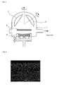
- Fig. 1 shows the schematic configuration of the off-axis sputtering system.
- the off-axis sputtering system includes a deposition chamber 1, a holder (substrate holder) 2 which is placed in the deposition chamber 1 and which holds a substrate (not shown) to be coated with the ZnO layer, a target 3 placed in the deposition chamber 1, and a shutter 4 placed between the target 2 and the substrate, which is held with the holder 2.
- the deposition chamber 1 is configured such that the deposition chamber 1 can be evacuated and the target 3 can be supplied with pulsed DC power.
- the off-axis sputtering system is configured such that the layer can be formed in such a state that the substrate, which has a surface for growing the layer, is placed outside a space which is located in the direction perpendicular to the target and in which high-energy particles come with high probability.
- the off-axis sputtering system is capable of forming the layer in such a manner that the composition of the layer is controlled such that the layer composition hardly differs from the composition of the target.
- the target 3 has a sintered density of 80% or more, a two-dimensional size of 315 mm ⁇ 118 mm, and a thickness of 5 mm.
- the substrate is made of at least one selected from the group consisting of glass, quartz, sapphire, Si, SiC, polyethylene terephthalate (PET), polyethylene naphthalate (PEN), polyethersulfone (PES), polyimide, cycloolefinic polymers, and polycarbonate. Even if the substrate is made of any one of the above materials, the substrate is surface-cleaned in advance of deposition in such a manner that the substrate is washed with isopropyl alcohol and irradiated with UV light.
- the substrate is set in the deposition chamber 1 of the off-axis sputtering system and the deposition chamber 1 is then evacuated to 5.5 ⁇ 10 -5 Pa. After evacuation, a high-purity Ar gas used as a sputtering gas is introduced into the deposition chamber 1 such that the pressure therein is increased to a predetermined value.
- the target 3 is sputtered in such a manner that a pulsed DC power with a predetermined pulse width is applied to the target 3 at a predetermined frequency.
- the thickness of a layer obtained by sputtering is set to 400 nm.
- the obtained ZnO layer is patterned by wet etching and then measured for thickness with a probe profilometer, whereby the ZnO layer is checked whether the ZnO layer has a set thickness.
- the ZnO layer is analyzed for composition, whereby the ZnO layer is checked whether the composition thereof is the same as that of the target.
- Layers prepared in examples or comparative examples each had a thickness substantially equal to a set thickness and the difference of the composition of each layer from that of a target was on an acceptable level.
- Variable sputtering conditions are principally the composition of the target (the type and dose of a group-III element), the type of the substrate, the pressure in the chamber, the rotation speed of the substrate, a pulsed DC power, a pulse width, and a pulse frequency.
- Fig. 2 is a cross-sectional SEM image of an Al-doped ZnO (AZO) layer, according to Example 1, having a granular crystal structure.
- the ZnO layer was prepared under conditions below.
- Target ZnO-mixed sintered body containing 3.0 weight percent Al 2 O 3
- Type of substrate alkali-free glass (Corning 1737)
- Pressure in chamber 0.1 Pa
- Rotation of substrate not rotated
- Pulsed DC power 2000 W
- Pulse width 2 ⁇ s Pulse frequency: 100 kHz
- the following layer was confirmed to have a granular crystal structure: a Ga-doped ZnO (GZO) layer, which is not shown, prepared using a ZnO-mixed sintered body containing 5.7 weight percent Ga 2 O 3 used as a target.
- GZO Ga-doped ZnO
- FIG. 3 is a cross-sectional SEM image of an Al-doped ZnO (AZO) layer, according to a comparative example, having a columnar crystal structure.
- AZO Al-doped ZnO
- GZO Ga-doped ZnO
- the ZnO layers according to the example and the comparative example were measured for resistivity by a four-probe technique.
- the ZnO layers according to the example and the comparative example were measured for sheet resistance.
- the ZnO layers according to the example and the comparative example were measured for transmittance at visible wavelengths. All the ZnO layers were confirmed to have a transmittance of 80% or more at visible wavelengths.
- Example 1 The ZnO layers according to Example 1 and Comparative Example, that is, the following layers were measured for change in resistivity with time in an atmosphere with a relative humidity of 85% at 85°C:
- Fig. 4 confirms that the granular crystalline region-including Al-doped ZnO (AZO) layer specified in Item (a) and the granular crystalline region-including Ga-doped ZnO (GZO) layer specified in Item (b) have a small change in resistivity with time and the columnar crystalline region-including Al-doped ZnO (AZO) layer specified in Item (c) and the columnar crystalline region-including Ga-doped ZnO (GZO) layer specified in Item (d), however, have a large change in resistivity with time.
- AZO Al-doped ZnO
- GZO Ga-doped ZnO
- Several types of targets having different Al 2 O 3 or Ga 2 O 3 contents were prepared. ZnO layers were formed under conditions similar to those described in Example 1 using the targets in such a manner that the dose of each group-III element was varied in four steps: 3.0, 5.7, 10.0, and 15.0 weight percent on an oxide mass basis. The obtained ZnO layers were used to investigate the relationship between the dose of the group-III element and the resistivity of the ZnO layers.
- Fig. 5 shows the data obtained using Al, which is a group-III element.
- a ZnO layer used as a transparent conductive film, for practical use has a resistivity of 1.2 ⁇ 10 -3 ⁇ cm or less.
- Fig. 5 confirms that the resistivity is 1.2 ⁇ 10 -3 ⁇ cm or less when the dose of the group-III element is within a range from 0.8 to 11.5 weight percent. Therefore, the dose of the group-III element is preferably within a range from 0.8 to 11.5 weight percent on an oxide mass basis.
- Fig. 5 shows the data obtained using Al, which is a group-III element.
- Example 2 confirms that the relationship between the dose of the group-III element and the resistivity of the ZnO layers does not significantly vary even if the group-III element is Al or Ga.
- the ZnO layers of Example 2 which are different in the dose of each group-III element from the ZnO layers of Example 1, are confirmed to have the granular crystal structure even if the dose of the group-III element is zero, although the crystal structures are not shown.
- Several types of targets having different Al 2 O 3 or Ga 2 O 3 contents were prepared in the same manner as that described in Example 2.
- ZnO layers were formed under conditions similar to those described in Example 1 using the targets in such a manner that the dose of each group-III element was varied in four steps: 3.0, 5.7, 10.0, and 15.0 weight percent on an oxide mass basis.
- the obtained ZnO layers were used to investigate the relationship between the dose of the group-III element and the full width at half maximum (FWHM) of the ZnO (002) rocking curve of each ZnO layer.
- Fig. 6 shows the data obtained using Al, which is a group-III element.
- Example 2 confirms that in order to allow the ZnO layers to have a resistivity suitable for use as transparent conductive films, the dose of the group-III element is preferably within a range from 0.8 to 11.5 weight percent on an oxide mass basis as described above.
- Example 3 ( Fig. 6 ) confirms that the full width at half maximum (FWHM) of the ZnO (002) rocking curve is preferably 10.5 degrees or less.
- Example 3 confirms that in order to allow the ZnO layers to have a resistivity of 1.2 ⁇ 10 -3 ⁇ cm suitable for use as transparent conductive films, the full width at half maximum (FWHM) of the ZnO (002) rocking curve is preferably 10.5 degrees or less.
- Fig. 6 shows the data obtained using Al, which is a group-III element.
- Example 3 confirms that the relationship between the dose and the full width at half maximum (FWHM) of the ZnO (002) rocking curve of each ZnO layer does not significantly vary even if the group-III element is Al or Ga.
- Substrates flexible substrates made of PEN (polyethylene naphthalate) were used instead of the glass substrate, made of alkali-free glass, used in Example 1.
- ZnO layers transparent conductive films
- Al or Ga are formed on the flexible substrates under the same conditions as those described in one of Examples 1 to 3 in the same manner as that described in one of Examples 1 to 3.
- the obtained ZnO layers were characterized under the same conditions as those described in one of the above examples. This confirmed that the ZnO layers (transparent conductive films) had substantially the same properties as those described in one of Examples 1 to 3.
- the ZnO layers (not shown) of Example 4 were confirmed to have a granular crystal structure. This confirms that a practical transparent conductive film can be formed on a substrate (flexible substrate) made of PEN (polyethylene naphthalate), which is versatile.
- Substrates flexible substrates made of PET (polyethylene terephthalate) were used instead of the glass substrate, made of alkali-free glass, used in Example 1.
- ZnO layers transparent conductive films
- Al or Ga are formed on the flexible substrates under the same conditions as those described in one of Examples 1 to 3 in the same manner as that described in one of Examples 1 to 3.
- the obtained ZnO layers were characterized under the same conditions as those described in one of the above examples. This confirmed that the ZnO layers (transparent conductive films) had substantially the same properties as those described in one of Examples 1 to 3.
- the ZnO layers of Example 5 were confirmed to have a granular crystal structure, although the crystal structures are not shown. This confirms that a practical transparent conductive film can be formed on a substrate (flexible substrate) made of PET (polyethylene terephthalate), which is versatile.
- the ZnO layers were formed on the glass substrates, the PEN substrates, or the PET substrates.
- a ZnO layer (transparent conductive film) according to the present invention may be formed on a single-crystalline substrate made of quartz, sapphire, or Si or a substrate made of SiC, polyethersulfone (PES), polyimide, a cycloolefinic polymer, or polycarbonate.
- PES polyethersulfone
- polyimide polyimide
- a cycloolefinic polymer or polycarbonate.
- the conditions described in Examples 1 to 5 are some of preferred exemplary conditions capable of efficiently growing granular crystals.
- conditions such as a chamber pressure, the dose of a group-III element and the type of a substrate are not dominant conditions in growing granular crystals.
- the conditions fixed through Examples 1 to 5 it is unclear that which condition is dominant.
- overall conditions including several sub-conditions probably need to be optimized. Even if the overall conditions are different from those described in Examples 1 to 5, granular crystals can be probably grown as long as the overall conditions are optimized.
- the present invention is not limited to the above examples.
- the followings may be variously adapted or modified within the scope of the present invention: the shape of a substrate for forming a ZnO layer (transparent conductive film), the type of a material for forming the substrate, the type and dose of a group-III element, and conditions for forming the ZnO layer.
- a ZnO-based transparent conductive film can be efficiently and securely produced.
- the ZnO-based transparent conductive film has humidity resistance sufficient for practical use and properties necessary for transparent conductive films and is cost-effective. Accordingly, the present invention can be widely used for various applications such as transparent electrodes for flat panel displays or solar cells.
Landscapes
- Chemical & Material Sciences (AREA)
- Engineering & Computer Science (AREA)
- Organic Chemistry (AREA)
- Materials Engineering (AREA)
- Mechanical Engineering (AREA)
- Metallurgy (AREA)
- Chemical Kinetics & Catalysis (AREA)
- Manufacturing & Machinery (AREA)
- Physical Vapour Deposition (AREA)
- Non-Insulated Conductors (AREA)
- Manufacturing Of Electric Cables (AREA)
- Conductive Materials (AREA)
- Inorganic Compounds Of Heavy Metals (AREA)
Applications Claiming Priority (2)
| Application Number | Priority Date | Filing Date | Title |
|---|---|---|---|
| JP2007230347 | 2007-09-05 | ||
| PCT/JP2008/064708 WO2009031399A1 (fr) | 2007-09-05 | 2008-08-18 | Film conducteur transparent et procédé de fabrication associé |
Publications (2)
| Publication Number | Publication Date |
|---|---|
| EP2071586A1 true EP2071586A1 (fr) | 2009-06-17 |
| EP2071586A4 EP2071586A4 (fr) | 2014-03-05 |
Family
ID=40428720
Family Applications (1)
| Application Number | Title | Priority Date | Filing Date |
|---|---|---|---|
| EP08826879.2A Withdrawn EP2071586A4 (fr) | 2007-09-05 | 2008-08-18 | Film conducteur transparent et procédé de fabrication associé |
Country Status (7)
| Country | Link |
|---|---|
| US (1) | US20090269588A1 (fr) |
| EP (1) | EP2071586A4 (fr) |
| JP (1) | JP5040991B2 (fr) |
| KR (1) | KR101041655B1 (fr) |
| CN (1) | CN101548343A (fr) |
| TW (1) | TWI453766B (fr) |
| WO (1) | WO2009031399A1 (fr) |
Families Citing this family (11)
| Publication number | Priority date | Publication date | Assignee | Title |
|---|---|---|---|---|
| KR101093424B1 (ko) | 2009-11-10 | 2011-12-14 | 삼성모바일디스플레이주식회사 | 유기전계발광 표시 장치 및 그의 제조 방법 |
| JP5630747B2 (ja) * | 2010-05-14 | 2014-11-26 | リンテック株式会社 | 酸化亜鉛系導電性積層体及びその製造方法並びに電子デバイス |
| JP5533448B2 (ja) * | 2010-08-30 | 2014-06-25 | 住友金属鉱山株式会社 | 透明導電膜積層体及びその製造方法、並びに薄膜太陽電池及びその製造方法 |
| JP2012144384A (ja) * | 2011-01-07 | 2012-08-02 | Tokyo Institute Of Technology | 導電性酸化亜鉛膜の製造方法 |
| KR101178496B1 (ko) * | 2011-09-28 | 2012-09-07 | 한국에너지기술연구원 | 이중구조의 투명전도막 및 그 제조방법 |
| CN105051244B (zh) * | 2012-10-08 | 2018-11-16 | 康宁股份有限公司 | 溅射的透明导电的铝掺杂的氧化锌膜 |
| TW201422835A (zh) * | 2012-12-03 | 2014-06-16 | Solar Applied Mat Tech Corp | 濺鍍靶材及導電金屬氧化物薄膜 |
| WO2016035721A1 (fr) * | 2014-09-04 | 2016-03-10 | 日本碍子株式会社 | Corps fritté à base d'oxyde de zinc et son procédé de fabrication |
| JP2019098523A (ja) * | 2017-11-28 | 2019-06-24 | 日本ゼオン株式会社 | 導電フィルム用多層フィルム及び導電フィルム |
| CN114361267B (zh) * | 2021-12-13 | 2024-08-09 | 中国科学院上海微系统与信息技术研究所 | 一种shj太阳电池双层tco薄膜结构及其制备方法 |
| KR102919169B1 (ko) * | 2023-10-18 | 2026-01-27 | 중앙대학교 산학협력단 | 고투과도 고전도성 반도체 기판, 이의 제조 방법 및 반도체 기판 전도성 향상 방법 |
Family Cites Families (24)
| Publication number | Priority date | Publication date | Assignee | Title |
|---|---|---|---|---|
| US3471721A (en) * | 1966-10-25 | 1969-10-07 | Minnesota Mining & Mfg | Zinc oxide maximum efficiency length extensional crystals and devices |
| US3846649A (en) * | 1973-06-18 | 1974-11-05 | Rca Corp | Piezoelectric transducer comprising oriented zinc oxide film and method of manufacture |
| NL7908501A (nl) * | 1979-11-22 | 1981-06-16 | Philips Nv | Lichamen samengesteld uit ten minste twee delen, verbindingsglas en werkwijze voor het aan elkaar hechten van delen. |
| JPH0731950B2 (ja) * | 1985-11-22 | 1995-04-10 | 株式会社リコー | 透明導電膜の製造方法 |
| EP0578046B1 (fr) * | 1992-07-10 | 1996-11-06 | Asahi Glass Company Ltd. | Couche conductrice transparente, et cible de pulvérisation et matériau pour la déposition de vapeur utilisés pour sa production |
| JPH06248427A (ja) * | 1993-02-26 | 1994-09-06 | Asahi Glass Co Ltd | 真空蒸着用原料 |
| JP3453805B2 (ja) * | 1992-09-11 | 2003-10-06 | 旭硝子株式会社 | 透明導電膜 |
| JPH07249316A (ja) * | 1994-03-10 | 1995-09-26 | Asahi Glass Co Ltd | 透明導電膜および該透明導電膜を用いた透明基体 |
| US5804466A (en) * | 1996-03-06 | 1998-09-08 | Canon Kabushiki Kaisha | Process for production of zinc oxide thin film, and process for production of semiconductor device substrate and process for production of photoelectric conversion device using the same film |
| JP4663829B2 (ja) * | 1998-03-31 | 2011-04-06 | 三菱電機株式会社 | 薄膜トランジスタおよび該薄膜トランジスタを用いた液晶表示装置 |
| JP3276930B2 (ja) * | 1998-11-17 | 2002-04-22 | 科学技術振興事業団 | トランジスタ及び半導体装置 |
| JP2000276943A (ja) * | 1999-03-26 | 2000-10-06 | Tohoku Ricoh Co Ltd | 透明導電膜 |
| KR20020003558A (ko) * | 2000-02-04 | 2002-01-12 | 오츠카 유지로 | 인듐아연산화물계의 육방정계 층상화합물 및 그의 제조방법 |
| JP4622075B2 (ja) * | 2000-10-03 | 2011-02-02 | 凸版印刷株式会社 | 透明導電性材料およびその製造方法 |
| US7118936B2 (en) * | 2001-10-11 | 2006-10-10 | Bridgestone Corporation | Organic dye-sensitized metal oxide semiconductor electrode and its manufacturing method, and organic dye-sensitized solar cell |
| JP3749498B2 (ja) * | 2002-03-26 | 2006-03-01 | スタンレー電気株式会社 | 結晶成長用基板およびZnO系化合物半導体デバイス |
| JP4277506B2 (ja) * | 2002-10-24 | 2009-06-10 | 株式会社村田製作所 | 熱電変換素子の熱電材料用のZnO系薄膜、該ZnO系薄膜を用いた熱電変換素子、及び赤外線センサ |
| KR100968560B1 (ko) * | 2003-01-07 | 2010-07-08 | 삼성전자주식회사 | 박막 트랜지스터 기판 및 박막 트랜지스터 기판의금속배선 형성방법 |
| CN1278385C (zh) * | 2003-03-25 | 2006-10-04 | 浙江大学 | 一种p-ZnO薄膜及其制备方法 |
| JP2004296616A (ja) * | 2003-03-26 | 2004-10-21 | Canon Inc | 光起電力素子 |
| US6946928B2 (en) * | 2003-10-30 | 2005-09-20 | Agilent Technologies, Inc. | Thin-film acoustically-coupled transformer |
| WO2007072950A1 (fr) * | 2005-12-22 | 2007-06-28 | Mitsui Mining & Smelting Co., Ltd. | Procede de configuration de film conducteur transparent d’oxyde de zinc |
| US7867636B2 (en) * | 2006-01-11 | 2011-01-11 | Murata Manufacturing Co., Ltd. | Transparent conductive film and method for manufacturing the same |
| KR101057571B1 (ko) * | 2007-02-26 | 2011-08-17 | 가부시키가이샤 무라타 세이사쿠쇼 | 도전막 및 도전막의 제조방법 |
-
2008
- 2008-08-18 KR KR1020097006617A patent/KR101041655B1/ko not_active Expired - Fee Related
- 2008-08-18 EP EP08826879.2A patent/EP2071586A4/fr not_active Withdrawn
- 2008-08-18 JP JP2009504162A patent/JP5040991B2/ja not_active Expired - Fee Related
- 2008-08-18 WO PCT/JP2008/064708 patent/WO2009031399A1/fr not_active Ceased
- 2008-08-18 CN CNA2008800008896A patent/CN101548343A/zh active Pending
- 2008-08-21 TW TW97131963A patent/TWI453766B/zh not_active IP Right Cessation
-
2009
- 2009-07-10 US US12/500,694 patent/US20090269588A1/en not_active Abandoned
Also Published As
| Publication number | Publication date |
|---|---|
| JPWO2009031399A1 (ja) | 2010-12-09 |
| JP5040991B2 (ja) | 2012-10-03 |
| US20090269588A1 (en) | 2009-10-29 |
| TWI453766B (zh) | 2014-09-21 |
| WO2009031399A1 (fr) | 2009-03-12 |
| KR20090094067A (ko) | 2009-09-03 |
| EP2071586A4 (fr) | 2014-03-05 |
| TW200929268A (en) | 2009-07-01 |
| CN101548343A (zh) | 2009-09-30 |
| KR101041655B1 (ko) | 2011-06-14 |
Similar Documents
| Publication | Publication Date | Title |
|---|---|---|
| US20090269588A1 (en) | Transparent conductive film and method of producing transparent conductive film | |
| JP5181677B2 (ja) | 透明導電膜 | |
| EP2061041A1 (fr) | Film conducteur et procede de production de film conducteur | |
| US8303856B2 (en) | Conductive laminated body and method for preparing the same | |
| CN107074662B (zh) | 金属氧化物薄膜,沉积金属氧化物薄膜的方法及包含金属氧化物薄膜的装置 | |
| CN105845196B (zh) | 锰锡氧化物类透明导电氧化物及利用其的多层透明导电膜以及其制备方法 | |
| JP6979938B2 (ja) | 導電性透明アルミニウムドープ酸化亜鉛スパッタ膜 | |
| US20170175249A1 (en) | Thin metal film substrate and method for preparing the same | |
| JP6709171B2 (ja) | 透明導電膜及び透明導電膜の製造方法 | |
| KR102164629B1 (ko) | 복합체 투명 전극 | |
| JP4170507B2 (ja) | 透明導電膜の製造方法 | |
| KR101005973B1 (ko) | 도전 적층체 및 이의 제조방법 | |
| JP5632135B2 (ja) | ZnO膜の成膜方法 | |
| KR101807957B1 (ko) | 산화물 기반 고 전도성 유연 투명전극 및 이의 제조방법 | |
| TW202332581A (zh) | 具有作為透明導電膜之功能的積層體及其製造方法,以及該積層體製造用之氧化物濺鍍靶 | |
| CN117280428A (zh) | 具有作为透明导电膜的功能的层叠体及其制造方法以及该层叠体制造用氧化物溅射靶 |
Legal Events
| Date | Code | Title | Description |
|---|---|---|---|
| PUAI | Public reference made under article 153(3) epc to a published international application that has entered the european phase |
Free format text: ORIGINAL CODE: 0009012 |
|
| 17P | Request for examination filed |
Effective date: 20090203 |
|
| AK | Designated contracting states |
Kind code of ref document: A1 Designated state(s): AT BE BG CH CY CZ DE DK EE ES FI FR GB GR HR HU IE IS IT LI LT LU LV MC MT NL NO PL PT RO SE SI SK TR |
|
| AX | Request for extension of the european patent |
Extension state: AL BA MK RS |
|
| DAX | Request for extension of the european patent (deleted) | ||
| A4 | Supplementary search report drawn up and despatched |
Effective date: 20140205 |
|
| RIC1 | Information provided on ipc code assigned before grant |
Ipc: C23C 14/34 20060101ALI20140130BHEP Ipc: C23C 14/08 20060101AFI20140130BHEP |
|
| STAA | Information on the status of an ep patent application or granted ep patent |
Free format text: STATUS: THE APPLICATION IS DEEMED TO BE WITHDRAWN |
|
| 18D | Application deemed to be withdrawn |
Effective date: 20180301 |