EP2071700A1 - Dispositif de conversion ca/cc - Google Patents
Dispositif de conversion ca/cc Download PDFInfo
- Publication number
- EP2071700A1 EP2071700A1 EP07829242A EP07829242A EP2071700A1 EP 2071700 A1 EP2071700 A1 EP 2071700A1 EP 07829242 A EP07829242 A EP 07829242A EP 07829242 A EP07829242 A EP 07829242A EP 2071700 A1 EP2071700 A1 EP 2071700A1
- Authority
- EP
- European Patent Office
- Prior art keywords
- constituted
- capacity
- conversion device
- load
- storage unit
- Prior art date
- Legal status (The legal status is an assumption and is not a legal conclusion. Google has not performed a legal analysis and makes no representation as to the accuracy of the status listed.)
- Withdrawn
Links
Images
Classifications
-
- H—ELECTRICITY
- H02—GENERATION; CONVERSION OR DISTRIBUTION OF ELECTRIC POWER
- H02J—ELECTRIC POWER NETWORKS; CIRCUIT ARRANGEMENTS OR SYSTEMS FOR SUPPLYING OR DISTRIBUTING ELECTRIC POWER; SYSTEMS FOR STORING ELECTRIC ENERGY
- H02J3/00—Circuit arrangements for AC mains or AC distribution networks
- H02J3/28—Arrangements for balancing of the load in networks by storage of energy
- H02J3/32—Arrangements for balancing of the load in networks by storage of energy using batteries or super capacitors with converting means
-
- H—ELECTRICITY
- H02—GENERATION; CONVERSION OR DISTRIBUTION OF ELECTRIC POWER
- H02J—ELECTRIC POWER NETWORKS; CIRCUIT ARRANGEMENTS OR SYSTEMS FOR SUPPLYING OR DISTRIBUTING ELECTRIC POWER; SYSTEMS FOR STORING ELECTRIC ENERGY
- H02J3/00—Circuit arrangements for AC mains or AC distribution networks
- H02J3/28—Arrangements for balancing of the load in networks by storage of energy
Definitions
- the present invention relates to an AC-DC conversion device and, particularly, relates to the AC-DC conversion device having functions of an instantaneous voltage reduction countermeasure and a power interruption countermeasure.
- an AC-DC conversion device having a power storage unit
- a midnight power having a small electric power load is stored.
- the stored power is discharged during a daytime peak to perform a leveling of the load and to provide functions of an instantaneous voltage reduction countermeasure and a power interruption countermeasure for the AC-DC conversion device.
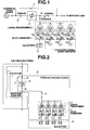
- Fig. 2 shows an AC-DC conversion device having such functions of the instantaneous voltage reduction countermeasure and the power interruption countermeasure as described above.
- 1 denotes an alternating current to direct current converter of AC/DC converters constituted by a plurality of unit converters 1a through 1d.
- a direct-current side of each of unit converters 1a through 1d is connected to a power storage unit 2 using secondary batteries such as NaS battery (Natrium-Sulfur battery).
- 3 denotes linking transformers, each output thereof being connected to an important load side line via a linking circuit breaker 4.
- 5 denotes a fast switch
- 6 denotes a received power circuit breaker
- 7 denotes a bypass circuit breaker
- 8 denotes a load side circuit breaker.
- PCS Power Conversion System
- An electric power is ordinarily supplied from an electric power system to the load.
- a control circuit opens fast switch 5 and the power stored in power storage unit 2 is supplied to the load via AC-DC converter 1, linking transformer 3, and linking circuit breaker 4.
- AC-DC converter 1 linking transformer 3
- linking circuit breaker 4 Such a device as described above is well known by, for example, a patent document 1.
- NaS batteries are used as the batteries for the power storage unit used in the AC-DC conversion device as described above.
- This NaS battery carries out a charge-and-discharge of a rated capacity. However, if limited to a short time, the discharge at three-times the rated capacity is possible. Utilizing the capabilities of the respective batteries, a load leveling drive at one time the rated capacity is carried out and an instantaneous reduction compensation driving at three times the rated capacity is carried out.
- the power storage unit is ordinarily constituted in the method of (1) or (2). If the parallel connections are carried out, a lateral current is caused to flow in the respective unit batteries to reduce the output due to an unevenness of an internal resistance of each unit battery. To prevent this output reduction, the serial connection is made.
- Patent document 1 a Japanese Patent Application First Publication (tokkai) No. 2004-23860 .
- device comprising: a commercial power source; a fast switch connected between the commercial power source and a load; and a PCS including an electric power storage unit, an AC-DC converter, and a linking transformer, the PCS being connected between the fast switch and the load, wherein a part of a capacity constituting the power storage unit is constituted by a secondary battery and the remainder of the capacity is constituted by electric double layer capacitors.
- a construction ratio of an electric energy between the NaS battery and the electric double layer capacitors is 30% or less for the NaS battery and 70% or more for the electrical double layer capacitors.
- the AC-DC converter is constituted by a plurality of unit converters.
- the AC-DC converter is constituted by a plurality of unit converters, each of the unit converters being provided with an individually separate control section.
- Fig. 1 shows a configuration view representing a preferred embodiment according to the present invention.
- the same reference numerals as those in Fig. 1 are designated to like parts or equivalent parts to Fig. 2 .
- a reference numeral 10 denotes a second power storage unit constituted by electric double layer capacitors and is constituted by a plurality of modules 10a through 10n. A case of four parallel connections is shown in Fig. 1 .
- a secondary battery such as an NaS battery, which has a high energy density and a small self-discharge, is used as first power storage unit 2.
- the NaS battery is used as the secondary battery and the electric double layer capacitors are connected to the AC-DC converter to compensate for large half or more electric powers required as second power storage unit 10.
- the NaS battery is used for 25% (30% or less) electric energy from among electric energies required and electric double layer capacitors are used for the remaining 75% (70% or more) which is divided into 10a through 10c. These electric double layer capacitors are, respectively, connected to unit converters 1b through 1d.
- a hybrid construction constituted by the NaS battery and electric double layer capacitors is taken as the power storage unit.
- the whole system becomes inexpensive since the electric double layer capacitors are inexpensive as compared with the NaS batteries.
- An application percentage is such that 30% or less for NaS batteries and 70% or more for the electric double layer capacitors.
- the system is advantageous in terms of the function and the cost.
- a control section for the divided unit converters 1a through 1d may be common but it may be considered that internal impedances and charge-discharge characteristics are different from each other since the individual electric double layer capacitors and linking transformers are connected to a plurality of respective unit AC-DC converters. If these matters are considered, it becomes more practical that individually different control sections are installed for the respective unit converters.
- the electric power is supplied from a commercial power source to a load side when each of circuit breakers 4 through 8 is turned on. In this state, an instantaneous voltage reduction occurs at the commercial power source side due to some reason.
- a fast switch 5 is immediately turned off and an inverter operation is started by any one or any combination of unit AC-DC converters 1a through 1d of AC-DC converter 1 corresponding to the predetermined voltage reduction rate and the energy stored in NaS battery 2 and electric double layer capacitors 10 as a power source is supplied to an important load side via linking transformer 3 and circuit breakers 4 and 8 by a predetermined electric power. Its supply of the electric power is continued until a voltage between fast switch 5 and the commercial power source is recovered.
- the electric power supply from PCS to the important load side is carried out in the same way as the instantaneous voltage reduction.
- the power interruption is determined when the detection level is reached to a predetermined power interruption threshold value exceeding the detection level of the instantaneous voltage reduction and both of a power source side circuit breaker 6 and a bypass circuit breaker 7 are turned off together with fast switch 5 so that the power supply to the important load side via power storage units 2, 10, AC-DC converter 1, linking transformer 3, and circuit breaker 8 is carried out.
- the power storage unit takes the hybrid construction of the NaS batteries (battery) and electric double layer capacitors.
- the whole system becomes small-sized and inexpensive even if the instantaneous voltage reduction compensation capacity » the load leveling capacity.
Landscapes
- Engineering & Computer Science (AREA)
- Power Engineering (AREA)
- Supply And Distribution Of Alternating Current (AREA)
- Charge And Discharge Circuits For Batteries Or The Like (AREA)
- Stand-By Power Supply Arrangements (AREA)
Applications Claiming Priority (2)
| Application Number | Priority Date | Filing Date | Title |
|---|---|---|---|
| JP2006272519 | 2006-10-04 | ||
| PCT/JP2007/069504 WO2008041755A1 (fr) | 2006-10-04 | 2007-10-04 | Dispositif de conversion ca/cc |
Publications (2)
| Publication Number | Publication Date |
|---|---|
| EP2071700A1 true EP2071700A1 (fr) | 2009-06-17 |
| EP2071700A4 EP2071700A4 (fr) | 2013-04-10 |
Family
ID=39268607
Family Applications (1)
| Application Number | Title | Priority Date | Filing Date |
|---|---|---|---|
| EP07829242.2A Withdrawn EP2071700A4 (fr) | 2006-10-04 | 2007-10-04 | Dispositif de conversion ca/cc |
Country Status (7)
| Country | Link |
|---|---|
| US (1) | US20090315402A1 (fr) |
| EP (1) | EP2071700A4 (fr) |
| JP (1) | JPWO2008041755A1 (fr) |
| KR (1) | KR20090045328A (fr) |
| CN (1) | CN101523691A (fr) |
| NZ (1) | NZ575465A (fr) |
| WO (1) | WO2008041755A1 (fr) |
Cited By (1)
| Publication number | Priority date | Publication date | Assignee | Title |
|---|---|---|---|---|
| EP3188343A1 (fr) * | 2016-01-04 | 2017-07-05 | Schneider Electric IT Corporation | Centre de données cc basé sur un module décentralisé |
Families Citing this family (5)
| Publication number | Priority date | Publication date | Assignee | Title |
|---|---|---|---|---|
| EP2294687B1 (fr) * | 2008-06-27 | 2016-08-24 | ABB Research Ltd. | Disposition de source d énergie à batteries et système de transformation de tension source |
| CN102427272A (zh) * | 2010-11-25 | 2012-04-25 | 上海市电力公司 | 电池储能监控调度系统及其控制方法 |
| KR101058351B1 (ko) | 2011-01-24 | 2011-08-22 | 주식회사 케이엘 | 레귤레이터와 인버터를 갖는 배터리 충전/방전 제어회로 |
| WO2014141396A1 (fr) * | 2013-03-13 | 2014-09-18 | 株式会社 日立製作所 | Dispositif de source d'énergie |
| EP3214724B1 (fr) | 2016-03-03 | 2020-04-29 | Lg Chem, Ltd. | Système de stockage d'énergie électrique utilisant une batterie |
Family Cites Families (70)
| Publication number | Priority date | Publication date | Assignee | Title |
|---|---|---|---|---|
| US4470407A (en) * | 1982-03-11 | 1984-09-11 | Laserscope, Inc. | Endoscopic device |
| US4445892A (en) * | 1982-05-06 | 1984-05-01 | Laserscope, Inc. | Dual balloon catheter device |
| US4619247A (en) * | 1983-03-31 | 1986-10-28 | Sumitomo Electric Industries, Ltd. | Catheter |
| US4976710A (en) * | 1987-01-28 | 1990-12-11 | Mackin Robert A | Working well balloon method |
| US4961738A (en) * | 1987-01-28 | 1990-10-09 | Mackin Robert A | Angioplasty catheter with illumination and visualization within angioplasty balloon |
| US5090959A (en) * | 1987-04-30 | 1992-02-25 | Advanced Cardiovascular Systems, Inc. | Imaging balloon dilatation catheter |
| US5372138A (en) * | 1988-03-21 | 1994-12-13 | Boston Scientific Corporation | Acousting imaging catheters and the like |
| US5514153A (en) * | 1990-03-02 | 1996-05-07 | General Surgical Innovations, Inc. | Method of dissecting tissue layers |
| US5370647A (en) * | 1991-01-23 | 1994-12-06 | Surgical Innovations, Inc. | Tissue and organ extractor |
| DE4338758C2 (de) * | 1992-11-13 | 2001-08-09 | Scimed Life Systems Inc | Katheteranordnung |
| US6923805B1 (en) * | 1992-11-13 | 2005-08-02 | Scimed Life Systems, Inc. | Electrophysiology energy treatment devices and methods of use |
| CA2165829A1 (fr) * | 1993-07-01 | 1995-01-19 | John E. Abele | Catheters pour la visualisation, la detection de potentiel electrique et l'ablation |
| US6129724A (en) * | 1993-10-14 | 2000-10-10 | Ep Technologies, Inc. | Systems and methods for forming elongated lesion patterns in body tissue using straight or curvilinear electrode elements |
| US6572609B1 (en) * | 1999-07-14 | 2003-06-03 | Cardiofocus, Inc. | Phototherapeutic waveguide apparatus |
| US5908445A (en) * | 1996-10-28 | 1999-06-01 | Ep Technologies, Inc. | Systems for visualizing interior tissue regions including an actuator to move imaging element |
| AU6673498A (en) * | 1997-03-10 | 1998-09-29 | Robin Medical Inc. | Method and apparatus for the assessment and display of variability in mechanicalactivity of the heart, and enhancement of ultrasound contrast imaging by variab ility analysis |
| US5941845A (en) * | 1997-08-05 | 1999-08-24 | Irvine Biomedical, Inc. | Catheter having multiple-needle electrode and methods thereof |
| US6997925B2 (en) * | 1997-07-08 | 2006-02-14 | Atrionx, Inc. | Tissue ablation device assembly and method for electrically isolating a pulmonary vein ostium from an atrial wall |
| US6179832B1 (en) * | 1997-09-11 | 2001-01-30 | Vnus Medical Technologies, Inc. | Expandable catheter having two sets of electrodes |
| US7090683B2 (en) * | 1998-02-24 | 2006-08-15 | Hansen Medical, Inc. | Flexible instrument |
| US20020095175A1 (en) * | 1998-02-24 | 2002-07-18 | Brock David L. | Flexible instrument |
| US6115626A (en) * | 1998-03-26 | 2000-09-05 | Scimed Life Systems, Inc. | Systems and methods using annotated images for controlling the use of diagnostic or therapeutic instruments in instruments in interior body regions |
| US7263397B2 (en) * | 1998-06-30 | 2007-08-28 | St. Jude Medical, Atrial Fibrillation Division, Inc. | Method and apparatus for catheter navigation and location and mapping in the heart |
| US6139508A (en) * | 1998-08-04 | 2000-10-31 | Endonetics, Inc. | Articulated medical device |
| JP3082849B2 (ja) * | 1998-08-17 | 2000-08-28 | サンケン電気株式会社 | 無停電電源装置 |
| JP2000102174A (ja) * | 1998-09-28 | 2000-04-07 | Nissin Electric Co Ltd | 電力供給装置 |
| US6178346B1 (en) * | 1998-10-23 | 2001-01-23 | David C. Amundson | Infrared endoscopic imaging in a liquid with suspended particles: method and apparatus |
| JP2000197347A (ja) * | 1998-12-25 | 2000-07-14 | Hitachi Ltd | 電源装置 |
| US6896690B1 (en) * | 2000-01-27 | 2005-05-24 | Viacor, Inc. | Cardiac valve procedure methods and devices |
| US6396873B1 (en) * | 1999-02-25 | 2002-05-28 | Envision Advanced Medical Systems | Optical device |
| JP2000295784A (ja) * | 1999-04-08 | 2000-10-20 | Sekisui Chem Co Ltd | 電力貯蔵システム |
| US6167297A (en) * | 1999-05-05 | 2000-12-26 | Benaron; David A. | Detecting, localizing, and targeting internal sites in vivo using optical contrast agents |
| AUPQ115499A0 (en) * | 1999-06-24 | 1999-07-15 | Colocare Holdings Pty Limited | Colostomy pump device |
| US6235044B1 (en) * | 1999-08-04 | 2001-05-22 | Scimed Life Systems, Inc. | Percutaneous catheter and guidewire for filtering during ablation of mycardial or vascular tissue |
| US6755811B1 (en) * | 1999-08-25 | 2004-06-29 | Corazon Technologies, Inc. | Methods and devices for reducing the mineral content of a region of non-intimal vascular tissue |
| US6315778B1 (en) * | 1999-09-10 | 2001-11-13 | C. R. Bard, Inc. | Apparatus for creating a continuous annular lesion |
| US6385476B1 (en) * | 1999-09-21 | 2002-05-07 | Biosense, Inc. | Method and apparatus for intracardially surveying a condition of a chamber of a heart |
| US7019610B2 (en) * | 2002-01-23 | 2006-03-28 | Stereotaxis, Inc. | Magnetic navigation system |
| JP2001260718A (ja) * | 2000-03-16 | 2001-09-26 | Railway Technical Res Inst | 電鉄用直流電力供給設備 |
| JP2002034179A (ja) * | 2000-07-14 | 2002-01-31 | Toshiba Corp | 電力制御装置 |
| US7399271B2 (en) * | 2004-01-09 | 2008-07-15 | Cardiokinetix, Inc. | Ventricular partitioning device |
| US6605055B1 (en) * | 2000-09-13 | 2003-08-12 | Cardiofocus, Inc. | Balloon catheter with irrigation sheath |
| JP2002177198A (ja) * | 2000-10-02 | 2002-06-25 | Olympus Optical Co Ltd | 内視鏡 |
| US6635070B2 (en) * | 2001-05-21 | 2003-10-21 | Bacchus Vascular, Inc. | Apparatus and methods for capturing particulate material within blood vessels |
| EP1434610A4 (fr) * | 2001-10-12 | 2008-07-30 | Applied Med Resources | Systeme d'irrigation a basse pression et a haut debit |
| JP2003125543A (ja) * | 2001-10-15 | 2003-04-25 | Ngk Insulators Ltd | 高温二次電池による電力貯蔵及び補償システム |
| US6979290B2 (en) * | 2002-05-30 | 2005-12-27 | The Board Of Trustees Of The Leland Stanford Junior University | Apparatus and methods for coronary sinus access |
| EP1530441B1 (fr) * | 2002-06-13 | 2017-08-02 | Ancora Heart, Inc. | Dispositifs et procedes de reparation de valvule cardiaque |
| JP2004023860A (ja) | 2002-06-14 | 2004-01-22 | Tokyo Electric Power Co Inc:The | 瞬低対策機能付き電力貯蔵用ナトリウム−硫黄電池システム |
| JP2004129412A (ja) * | 2002-10-03 | 2004-04-22 | Nissin Electric Co Ltd | 電力貯蔵装置 |
| US20040138707A1 (en) * | 2003-01-14 | 2004-07-15 | Greenhalgh E. Skott | Anchor removable from a substrate |
| EP1619769A4 (fr) * | 2003-03-11 | 2009-08-26 | Toshiba Kk | Systeme et commutateur d'alimentation electrique cc |
| US7658747B2 (en) * | 2003-03-12 | 2010-02-09 | Nmt Medical, Inc. | Medical device for manipulation of a medical implant |
| US20050015048A1 (en) * | 2003-03-12 | 2005-01-20 | Chiu Jessica G. | Infusion treatment agents, catheters, filter devices, and occlusion devices, and use thereof |
| US7300429B2 (en) * | 2003-03-18 | 2007-11-27 | Catharos Medical Systems, Inc. | Methods and devices for retrieval of a medical agent from a physiological efferent fluid collection site |
| EP1644077A4 (fr) * | 2003-03-18 | 2012-01-04 | Catharos Medical Systems Inc | Procedes et dispositifs pour recuperer un agent medical d'un site de collecte de fluides physiologiques efferents |
| US6939348B2 (en) * | 2003-03-27 | 2005-09-06 | Cierra, Inc. | Energy based devices and methods for treatment of patent foramen ovale |
| US20040199052A1 (en) * | 2003-04-01 | 2004-10-07 | Scimed Life Systems, Inc. | Endoscopic imaging system |
| US7534204B2 (en) * | 2003-09-03 | 2009-05-19 | Guided Delivery Systems, Inc. | Cardiac visualization devices and methods |
| US8172747B2 (en) * | 2003-09-25 | 2012-05-08 | Hansen Medical, Inc. | Balloon visualization for traversing a tissue wall |
| JP3823321B2 (ja) * | 2003-12-25 | 2006-09-20 | 有限会社エスアールジェイ | バルーン制御装置 |
| US8021326B2 (en) * | 2004-03-05 | 2011-09-20 | Hansen Medical, Inc. | Instrument driver for robotic catheter system |
| US7527625B2 (en) * | 2004-08-04 | 2009-05-05 | Olympus Corporation | Transparent electrode for the radiofrequency ablation of tissue |
| US20060069303A1 (en) * | 2004-09-30 | 2006-03-30 | Couvillon Lucien A Jr | Endoscopic apparatus with integrated hemostasis device |
| US20080015569A1 (en) * | 2005-02-02 | 2008-01-17 | Voyage Medical, Inc. | Methods and apparatus for treatment of atrial fibrillation |
| US20080009747A1 (en) * | 2005-02-02 | 2008-01-10 | Voyage Medical, Inc. | Transmural subsurface interrogation and ablation |
| US8050746B2 (en) * | 2005-02-02 | 2011-11-01 | Voyage Medical, Inc. | Tissue visualization device and method variations |
| US10064540B2 (en) * | 2005-02-02 | 2018-09-04 | Intuitive Surgical Operations, Inc. | Visualization apparatus for transseptal access |
| US8355801B2 (en) * | 2005-09-26 | 2013-01-15 | Biosense Webster, Inc. | System and method for measuring esophagus proximity |
| US7918793B2 (en) * | 2005-10-28 | 2011-04-05 | Biosense Webster, Inc. | Synchronization of ultrasound imaging data with electrical mapping |
-
2007
- 2007-10-04 WO PCT/JP2007/069504 patent/WO2008041755A1/fr not_active Ceased
- 2007-10-04 EP EP07829242.2A patent/EP2071700A4/fr not_active Withdrawn
- 2007-10-04 KR KR1020097005036A patent/KR20090045328A/ko not_active Ceased
- 2007-10-04 JP JP2008537554A patent/JPWO2008041755A1/ja active Pending
- 2007-10-04 CN CNA200780036869XA patent/CN101523691A/zh active Pending
- 2007-10-04 US US12/440,848 patent/US20090315402A1/en not_active Abandoned
- 2007-10-04 NZ NZ575465A patent/NZ575465A/en not_active IP Right Cessation
Cited By (2)
| Publication number | Priority date | Publication date | Assignee | Title |
|---|---|---|---|---|
| EP3188343A1 (fr) * | 2016-01-04 | 2017-07-05 | Schneider Electric IT Corporation | Centre de données cc basé sur un module décentralisé |
| US10003200B2 (en) | 2016-01-04 | 2018-06-19 | Schneider Electric It Corporation | Decentralized module-based DC data center |
Also Published As
| Publication number | Publication date |
|---|---|
| CN101523691A (zh) | 2009-09-02 |
| WO2008041755A1 (fr) | 2008-04-10 |
| NZ575465A (en) | 2011-06-30 |
| JPWO2008041755A1 (ja) | 2010-02-04 |
| EP2071700A4 (fr) | 2013-04-10 |
| US20090315402A1 (en) | 2009-12-24 |
| KR20090045328A (ko) | 2009-05-07 |
Similar Documents
| Publication | Publication Date | Title |
|---|---|---|
| JP5508530B2 (ja) | バッテリシステム内のエネルギー伝達のためのスイッチングレギュレータの直列回路 | |
| US5160851A (en) | Rechargeable back-up battery system including a number of battery cells having float voltage exceeding maximum load voltage | |
| US6795322B2 (en) | Power supply with uninterruptible function | |
| US20120169124A1 (en) | Output circuit for power supply system | |
| KR101541960B1 (ko) | 고주파 링크형 직류-직류 컨버터를 이용한 에너지 저장 장치 | |
| JP2011120449A (ja) | 発電システム、制御装置および切替回路 | |
| CN115362610B (zh) | 具有多个lvdc输出的sst系统 | |
| CN113972817B (zh) | 固态变压器故障处理系统 | |
| EP2071700A1 (fr) | Dispositif de conversion ca/cc | |
| KR101587333B1 (ko) | 고신뢰성 배터리 에너지 저장 장치 | |
| KR102555492B1 (ko) | 전지 시스템용 제어 시스템, 전지 시스템 및 이를 포함하는 차량 | |
| JP2002064947A (ja) | 無停電直流電源装置 | |
| KR102796089B1 (ko) | 배터리 관리 시스템 및 밸런싱 방법 | |
| JP2022108532A (ja) | 無停電電源システム | |
| EP4723429A1 (fr) | Sous-module de soupape de stockage d'énergie et son procédé de fonctionnement, dispositif de soupape de stockage d'énergie et système de stockage d'énergie | |
| EP4108496B1 (fr) | Système d'alimentation bidirectionnelle pour alimenter un système de gestion de batterie d'un véhicule électrique | |
| US12149103B2 (en) | Secondary cell system | |
| EP4579999A1 (fr) | Alimentation de secours pour un contrôleur bms | |
| RU2794276C1 (ru) | Система бесперебойного питания | |
| EP4432502A2 (fr) | Architectures de bus en anneau alimente par pile a combustible | |
| JPH07107859B2 (ja) | 燃料電池の放電制御回路 | |
| EP4358348A1 (fr) | Système d'équilibrage de modules de batterie | |
| Narayan et al. | Single-Stage DC-DC Converter for Battery Balancing and Power Transfer Operation for EVs | |
| CN119209855A (zh) | 储能阀装置及其运行方法、储能系统 | |
| JP2004064996A (ja) | 電源装置 |
Legal Events
| Date | Code | Title | Description |
|---|---|---|---|
| PUAI | Public reference made under article 153(3) epc to a published international application that has entered the european phase |
Free format text: ORIGINAL CODE: 0009012 |
|
| 17P | Request for examination filed |
Effective date: 20090312 |
|
| AK | Designated contracting states |
Kind code of ref document: A1 Designated state(s): FR GB |
|
| AX | Request for extension of the european patent |
Extension state: AL BA HR MK RS |
|
| RBV | Designated contracting states (corrected) |
Designated state(s): AT BE BG CH CY CZ DE DK EE ES FI FR GB GR HU IE IS IT LI LT LU LV MC MT NL PL PT RO SE SI SK TR |
|
| RIN1 | Information on inventor provided before grant (corrected) |
Inventor name: FUKUDA, NARUHIKO, Inventor name: SUZUKI, KENICHI, |
|
| DAX | Request for extension of the european patent (deleted) | ||
| REG | Reference to a national code |
Ref country code: DE Ref legal event code: R108 |
|
| A4 | Supplementary search report drawn up and despatched |
Effective date: 20130307 |
|
| RIC1 | Information provided on ipc code assigned before grant |
Ipc: H02J 9/06 20060101AFI20130301BHEP Ipc: H02J 3/28 20060101ALI20130301BHEP Ipc: H02J 3/32 20060101ALI20130301BHEP |
|
| STAA | Information on the status of an ep patent application or granted ep patent |
Free format text: STATUS: THE APPLICATION IS DEEMED TO BE WITHDRAWN |
|
| 18D | Application deemed to be withdrawn |
Effective date: 20131008 |