EP2072423A1 - Convoyeur pour désempilage doté d'une surface flottante - Google Patents
Convoyeur pour désempilage doté d'une surface flottante Download PDFInfo
- Publication number
- EP2072423A1 EP2072423A1 EP08291224A EP08291224A EP2072423A1 EP 2072423 A1 EP2072423 A1 EP 2072423A1 EP 08291224 A EP08291224 A EP 08291224A EP 08291224 A EP08291224 A EP 08291224A EP 2072423 A1 EP2072423 A1 EP 2072423A1
- Authority
- EP
- European Patent Office
- Prior art keywords
- articles
- conveyor
- stationary surface
- stationary
- friction
- Prior art date
- Legal status (The legal status is an assumption and is not a legal conclusion. Google has not performed a legal analysis and makes no representation as to the accuracy of the status listed.)
- Granted
Links
Images

Classifications
-
- B—PERFORMING OPERATIONS; TRANSPORTING
- B65—CONVEYING; PACKING; STORING; HANDLING THIN OR FILAMENTARY MATERIAL
- B65G—TRANSPORT OR STORAGE DEVICES, e.g. CONVEYORS FOR LOADING OR TIPPING, SHOP CONVEYOR SYSTEMS OR PNEUMATIC TUBE CONVEYORS
- B65G21/00—Supporting or protective framework or housings for endless load-carriers or traction elements of belt or chain conveyors
- B65G21/20—Means incorporated in, or attached to, framework or housings for guiding load-carriers, traction elements or loads supported on moving surfaces
- B65G21/2045—Mechanical means for guiding or retaining the load on the load-carrying surface
- B65G21/2063—Mechanical means for guiding or retaining the load on the load-carrying surface comprising elements not movable in the direction of load-transport
- B65G21/209—Mechanical means for guiding or retaining the load on the load-carrying surface comprising elements not movable in the direction of load-transport for augmenting or creating a pression force between the load and the load-carrying surface
-
- B—PERFORMING OPERATIONS; TRANSPORTING
- B65—CONVEYING; PACKING; STORING; HANDLING THIN OR FILAMENTARY MATERIAL
- B65G—TRANSPORT OR STORAGE DEVICES, e.g. CONVEYORS FOR LOADING OR TIPPING, SHOP CONVEYOR SYSTEMS OR PNEUMATIC TUBE CONVEYORS
- B65G47/00—Article or material-handling devices associated with conveyors; Methods employing such devices
- B65G47/02—Devices for feeding articles or materials to conveyors
- B65G47/04—Devices for feeding articles or materials to conveyors for feeding articles
- B65G47/12—Devices for feeding articles or materials to conveyors for feeding articles from disorderly-arranged article piles or from loose assemblages of articles
- B65G47/14—Devices for feeding articles or materials to conveyors for feeding articles from disorderly-arranged article piles or from loose assemblages of articles arranging or orientating the articles by mechanical or pneumatic means during feeding
- B65G47/1492—Devices for feeding articles or materials to conveyors for feeding articles from disorderly-arranged article piles or from loose assemblages of articles arranging or orientating the articles by mechanical or pneumatic means during feeding the articles being fed from a feeding conveyor
Definitions
- the present disclosure relates to belt conveyors for conveying articles, and more particularly, to such conveyors for unstacking the articles.
- a belt conveyor can be arranged at a relatively steep angle to help unstack articles as they are being conveyed.
- the relatively steep angle can be at a downward angle (i . e ., declined) or at an upward angle (i.e., inclined).
- both a declined conveyor section and an inclined conveyor section can be used together in sequence.
- the angled conveyor can be made up of multiple conveyor belt segments, where each subsequent downstream belt can move at an increased belt travel speed to provide belt space for the upper articles as they slide off the lower articles.
- U.S. Patent No, 6,491,154 to Ydoate, et al discloses one exemplary unstacking belt conveyor, the disclosure of which is hereby incorporated herein by reference in its entirety.
- the present disclosure relates to a conveyor for unstacking articles in an article stream.
- This includes an angled conveyor and a stationary surface suspended above the angled conveyor to contact the article stream.
- the stationary surface may be positioned to exert a downward force on the articles.
- the stationary surface resists the tendency of articles to roll down toward the bottom of the angled conveyor.
- the disclosure provides an inclined conveyor and a stationary surface suspended above the inclined conveyor to contact the article stream.
- the stationary surface exerts a moment on one of the articles related to an effective weight of the stationary surface acting on the one of the articles. The moment is greater than a counter-moment exerted on the one of the articles related to a coefficient of friction of the stationary surface.
- a conveyor system for unstacking articles in a article stream including a feed conveyor, a declined conveyor, and an inclined conveyor.
- a declined stationary surface is provided and suspended above the declined conveyor and positioned to exert a counter-moment on the articles related to the weight of the declined stationary surface and the coefficient of sliding friction of the declined stationary support surface. The counter-moment is sufficient to resist forward rotation of the articles down the declined conveyor.
- An inclined stationary surface is provided suspended above the inclined conveyor and positioned to exert a forward-moment on the articles related to the weight of the inclined stationary surface and the coefficient of sliding friction of the inclined stationary surface. The forward-moment is sufficient to resist counter-rotation of the articles that results in movement of the articles down the inclined conveyor.
- the present disclosure also provides a method of unstacking articles in an article stream.
- the method may comprise suspending a stationary surface above an inclined conveyor. Articles may be fed along a conveyor to the inclined conveyor.
- the method includes exerting a forward conveying force on one of the articles due to friction between each article and the angled conveyor surface. A moment may be exerted on the one of the articles related to an effective weight of the stationary surface acting on the one of the articles that is greater than a counter-moment related to a coefficient of friction of the stationary surface acting on the one of the articles.
- the present disclosure provides positioning a declined stationary surface above a declined conveyor and feeding the articles to the declined conveyor.
- the articles may be sandwiched between the declined conveyor and the stationary surface during a declined sandwiching period.
- the method includes conveying the articles forward due to the declined conveyor during the declined sandwiching period and exerting a counter-moment on the articles related to the weight of the stationary support surface and the coefficient of friction of the stationary support surface.
- the counter-movement is sufficient to resist forward rotation of the articles down the declined conveyor during the declined sandwiching period.
- An inclined stationary surface may be positioned above an inclined conveyor and articles are fed to the inclined conveyor. The articles may be sandwiched between the inclined conveyor and the stationary surface during an inclined sandwiching period.
- the method further includes conveying the secondarily sandwiched articles forward due to the inclined conveyor during the inclined sandwiching period and exerting a forward-moment on the articles related to the weight of the inclined stationary surface and the coefficient of friction of the inclined stationary surface.
- the forward-movement is sufficient to resist counter-rotation of the articles that results in movement of the articles down the inclined conveyor during the inclined sandwiching period.
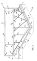
- Figure 1 is a side elevation view of one preferred embodiment of an unstacking conveyor
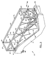
- Figure 2 is a simplified perspective view of the unstacking conveyor of Figure 1 ;
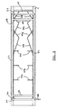
- Figure 3 is a top plan view of the unstacking conveyor of Figure 1 ;
- Figure 4 is an exploded partial elevation view of the unstacking conveyor of Figure 1 in operation.
- the unstacking conveyor 10 includes a conveyor 11 comprising a feed conveyor 12, and two angled conveyors 14 and 16; specifically a declined conveyor 14 and an inclined conveyor 16.
- Each of the angled conveyors 14 and 16 is made up of a plurality of individual angled conveyors 14a, 14b, 14c, and 16a, 16b, and 16c, respectively.
- Each of the conveyors 12, 14 and 16, include a moving conveying surface illustrated herein as a belt.
- the angled conveyors 14, 16 may also include at least one individual conveyor that is substantially horizontal. Additional details regarding the configuration and operation of such angled conveyors 14 and 16 is provided in previously incorporated U.S. Patent No. 6,491,154 to Ydoate, et al .
- the conveyor 11 simply comprises a single angled conveyor.
- the single angled conveyor is preferably an inclined conveyor 16.
- a support structure 18 is coupled to the conveyor 11.
- a support structure can be coupled to the building floor or other building structure.
- the support structure 18 includes a fixed support frame 19 comprising four upright corner posts 20.
- the posts 20 are coupled at their lower ends to the conveyor 11.
- the posts 20 are coupled to each other at their upper ends by a pair of longitudinal support rails 22 and a pair of transverse support rails 24.
- the fixed support frame 19 includes the posts 20, the longitudinal support rails 22 and the transverse support rails 24.
- the support structure 18 additionally includes a vertically movable support frame 25.
- the vertically movable support frame 25 includes a pair of longitudinal support rails 26 and a pair of transverse support rails 28 coupled together.
- One of the transverse support rails 28 is indirectly coupled to the pair of longitudinal support rails 26 via a bracket 30 that locates the transverse support rail 28 vertically above the longitudinal support rails 26.
- Such a configuration can be desirable to increase the initial contact angle as discussed hereinafter.
- the vertically movable support frame 25 is movably coupled to the fixed support frame 19.
- a bracket 32 (seen in Figure 2 ) is coupled to each end of the longitudinal support rails 26 to extend from the interior face at the ends of the longitudinal support rails 26.
- the movable support frame 25 is horizontally fixed in position in relation to the posts 20 of the fixed support frame 19, but can move vertically with the bracket 32 riding along the interior faces of the posts 20.
- Frame support lines 34 couple the movable support frame 25 to the fixed support frame 19 via brackets 40.
- the frame support lines 34 extend around pulleys 36 and through interior cavities of the posts 20 and rails 22 and 24 to a vertical adjustment mechanism 38.
- the vertical adjustment mechanism 38 includes a hand crank.
- the vertical adjustment mechanism can comprise an electronically controlled or manually actuated switch and motorized system.
- Surface support lines 44 couple the movable support frame 25 to a stationary surface 42 via brackets 46.
- lines includes wires, cables, string, twine, ropes and equivalent structures.
- stationary means that the surface does not move forward to impart any forward conveying force to any articles being conveyed. Instead, any limited forward movement of the surface results only from contact with articles being conveyed forward by the conveying system. To be clear, in this context stationary does not relate to movement of the surface which may occur in any other direction. Specifically, stationary does not relate to the potential for vertical movement of the surface.
- the surface support lines 44 all extend at an angle toward the middle of the stationary surface.
- the surface support lines 44 are provided in pairs 44a-44f so that a laterally outward force exerted on the stationary surface 42 by one of the surface support lines 44 is counterbalanced by the other surface support line in the pair. As a result, the surface support lines 44 tend to maintain the stationary surface centered above the angled conveyors 14 and 16.
- the surface support lines above the declined conveyor 44a-44c extend substantially vertically as viewed from a side elevation perspective as seen, for example, in Figure 1 .
- the input end of the stationary surface 42 is coupled to the transverse rail 28.
- the surface support lines 44a-44c and the transverse rail 28 tend to maintain the surface 42 in a stationary position above the declined conveyor 14.
- some of the surface support lines 44d-44f above the inclined conveyor 16 extend at an angle that is substantially perpendicular to a the stationary surface 42 in a resting position as viewed from a side elevation perspective. Some others of the surface support lines 44g-44h above the inclined conveyor 16 extend at an acute angle of the stationary surface 42 in a resting position as viewed from a side elevation perspective. As a result, the surface support lines 44 tend to maintain the surface in a stationary position above the inclined conveyor 16. As defined herein, the surface 42 is stationary despite limited forward movement that might occur as a result of the surface 42 being raised as articles pass under it. Such movement would typically be in a direction normal to the conveying surface. The surface support lines 44 suspend the stationary surface 42 above the conveyor 11 so that it does not contact the moving conveying surfaces thereof.
- the stationary surface 42 is positioned above the declined conveyor 14 to provide an input opening 48 between the declined conveyor 14 and the stationary surface 42.
- the stationary surface 42 is the downward facing surface (toward the conveyors 14 and 16) of the supported material.
- the input opening 48 is associated with a declined conveyor 14, but it may alternatively be associated with an inclined conveyor 16 or a feed conveyor 12.
- the height H of the input opening 48 is typically greater than the maximum expected height of the stream of articles being conveyed.
- the height H of the input opening 48 can optionally be adjustable.
- the frame support lines 34 and pulleys 36 are configured to raise and lower the vertically movable frame 25 through operation of the hand crank 38.
- the stationary surface 42 can be raised or lowered.
- vertical adjustment of the movable frame 25 can permit access to articles below the stationary surface 42.
- vertical adjustment of the movable frame 25 can permit selective use by positioning the stationary surface 42 at an appropriate height, or non-use of the stationary surface by raising the stationary surface 42 to a height at which it will not contact the article stream moving along the conveyor 11.
- an initial contact angle I Associated with the input opening 48 is an initial contact angle I between the declined conveyor 14 and the stationary surface 42.
- the articles initially contact the stationary surface 42 the initial contact angle I.
- This initial contact angle I is sufficiently small that any friction between the articles and the stationary surface 42 can be overcome by the friction between the articles and the declined conveyor 14. As a result, the articles continue to be conveyed along the declined conveyor 14 and are not stopped by their initial contact with the stationary surface 42.
- Friction from the contact between the stationary surface 42 and the articles, including the friction of this initial contact, can also be reduced by providing the stationary surface 42 with a low coefficient of friction.
- the coefficient of friction is preferably less than about 0.5; more preferably, less than about 0.4; and even more preferably, less than about 0.3.
- the stationary surface 42 can be provided by a uniform sheet of material, resulting in a coefficient of friction that is the same along the length of the stationary surface.
- Exemplary preferred materials include polycarbonate and low friction conveyor belting.
- the stationary surface is comprised of a uniform sheet of polycarbonate, having a thickness of about 1/8 inch. This material has the additional advantage of being transparent, which allows visual access to the articles through the stationary surface.
- different materials or coatings can be used to provide different coefficients of friction at different points along the length of the stationary surface, or to adjust the weight associated with the stationary surface 42, or both.
- the articles can be generally cube-shaped, i.e., all side dimensions are roughly equivalent.
- Such generally cubed-shaped articles have a tendency to forward-rotate on a declined conveyor 14, thereby rolling down the declined conveyor 14 toward the bottom thereof.
- such generally cube-shaped articles have a tendency to counter-rotate on an inclined conveyor 16, thereby rolling down the inclined conveyor 16 toward the bottom thereof.
- the weight associated with the stationary surface 42 resists the tendency of articles to roll down toward the bottom of the angled conveyor 14 and 16.
- the stationary surface 42 resists any tendency to roll down the angled conveyor 14 and 16.
- the declined conveyor 14 instead of forward-rotating as occurs with rolling down the angle conveyor, generally round articles will counter-rotate.
- the stationary conveyor 16 instead of tending to move down the angled conveyor 16 as occurs with rolling down the inclined conveyor 16, such generally round-shaped articles move up the inclined conveyor 16.
- Both the counter-rotation and moving up the inclined surface described above occur as a result of the generally round-shaped articles rolling on the stationary surface 42.
- the stationary surface 42 preferably generates sufficient friction to cause such generally round-shaped articles to roll on the stationary surface 42.
- a counter-directional resistance force F2 is a function of the friction coefficient, the stiffness contact angle S, and the force F1 resulting from the weight of the stationary surface acting on the article.
- the moment generated by F2 preferably does not exceed the upward force typically generated as a result of the F2 moment exceeding the total downward weight force F1. In other words, it may be beneficial for the cubic type items to slide along the stationary surface.
- the stiffness contact angle is preferably less than about 20 degrees; more preferably, less than about 15 degrees; and even more preferably, less than about 10 degrees.
- the thickness of the sheet is preferably from about 1/16 inches to about 3/16 inches; and more preferably, from about 3/32 inches to about 5/32 inches, or 1/8 inches. It should be understood, however, that the ideal thickness may vary with the size and weight of an article. For example, smaller articles may require thinner materials and larger articles may require thicker materials, assuming a similar flexural modulus.
- F1 and F2 are coordinated such that enough downward force is provided to resist or oppose such a downward rotation tendency.
- the conveyor system may include only an inclined conveyor.
- a declined conveyor would not be provided.
- the vertically movable support frame is eliminated in such an alternative preferred embodiment.
- the surface support lines would be attached directly to appropriately positioned longitudinal rails of a fixed support frame.
Landscapes
- Engineering & Computer Science (AREA)
- Mechanical Engineering (AREA)
- Belt Conveyors (AREA)
- Warehouses Or Storage Devices (AREA)
- Chutes (AREA)
- Rollers For Roller Conveyors For Transfer (AREA)
- Framework For Endless Conveyors (AREA)
Applications Claiming Priority (1)
| Application Number | Priority Date | Filing Date | Title |
|---|---|---|---|
| US11/962,916 US7938252B2 (en) | 2007-12-21 | 2007-12-21 | Unstacking conveyor with floating surface |
Publications (2)
| Publication Number | Publication Date |
|---|---|
| EP2072423A1 true EP2072423A1 (fr) | 2009-06-24 |
| EP2072423B1 EP2072423B1 (fr) | 2011-06-15 |
Family
ID=40352142
Family Applications (1)
| Application Number | Title | Priority Date | Filing Date |
|---|---|---|---|
| EP08291224A Active EP2072423B1 (fr) | 2007-12-21 | 2008-12-19 | Convoyeur pour désempilage doté d'une surface flottante |
Country Status (4)
| Country | Link |
|---|---|
| US (1) | US7938252B2 (fr) |
| EP (1) | EP2072423B1 (fr) |
| AT (1) | ATE512915T1 (fr) |
| WO (1) | WO2009085906A2 (fr) |
Cited By (3)
| Publication number | Priority date | Publication date | Assignee | Title |
|---|---|---|---|---|
| WO2011112449A3 (fr) * | 2010-03-08 | 2011-10-27 | Laitram, L.L.C. | Système de convoyeur et procédé de triage de paquets |
| US10246267B2 (en) | 2015-05-14 | 2019-04-02 | Laitram, L.L.C. | Inclined-roller destacker |
| EP3971116A1 (fr) * | 2020-09-17 | 2022-03-23 | Caljan A/S | Systèmes, dispositifs et procédés pour transporteurs extensibles |
Families Citing this family (13)
| Publication number | Priority date | Publication date | Assignee | Title |
|---|---|---|---|---|
| US9038810B2 (en) | 2013-03-12 | 2015-05-26 | Fives Intralogistics Corp. | Singulator conveyor |
| MX2019014605A (es) * | 2017-06-06 | 2020-08-20 | Mat Handling Systems Inc | Sistema y metodo para identificar y transferir paquetes desde un primer transportador a un segundo transportador. |
| US10875214B2 (en) * | 2017-09-13 | 2020-12-29 | Broadview Group International, Llc | Friction device for fiber-granule separation |
| US10870543B1 (en) * | 2019-03-29 | 2020-12-22 | Amazon Technologies, Inc. | Item singulation system and method |
| US11014765B1 (en) * | 2019-03-29 | 2021-05-25 | Amazon Technologies, Inc. | System and method for collimating items |
| US11753256B2 (en) | 2020-06-22 | 2023-09-12 | Material Handling Systems, Inc. | Conveyor system with multiple robot singulators |
| CN115479618B (zh) * | 2021-05-26 | 2026-03-10 | 泰科电子(上海)有限公司 | 载具和检查系统 |
| IT202300012084A1 (it) * | 2023-06-13 | 2024-12-13 | Mech Sistemi S R L | Trasportatore, sistema e procedimento di movimentazione di articoli |
| IT202400004471A1 (it) | 2024-02-29 | 2025-08-29 | Mech Sistemi S R L | Trasportatore, sistema e procedimento di movimentazione di articoli |
| IT202300012048A1 (it) * | 2023-06-13 | 2024-12-13 | Mech Sistemi S R L | Trasportatore, sistema e procedimento di movimentazione di articoli |
| IT202300012060A1 (it) * | 2023-06-13 | 2024-12-13 | Mech Sistemi S R L | Trasportatore, sistema e procedimento di movimentazione di articoli |
| IT202400002665A1 (it) | 2024-02-08 | 2025-08-08 | Mech Sistemi S R L | Trasportatore, sistema e procedimento di movimentazione di articoli |
| EP4477586A1 (fr) | 2023-06-13 | 2024-12-18 | Mechanica Sistemi S.r.L. | Transporteur, système et procédé de manipulation d'articles |
Citations (5)
| Publication number | Priority date | Publication date | Assignee | Title |
|---|---|---|---|---|
| BE664183A (fr) * | 1964-05-21 | 1965-11-19 | ||
| GB2017034A (en) * | 1978-03-18 | 1979-10-03 | Matsuo M | Belt conveyor apparatus |
| US5161678A (en) * | 1991-08-19 | 1992-11-10 | Garvey Corporation | Accumulator cover |
| DE9302962U1 (de) * | 1993-02-25 | 1993-05-13 | A. Hirschenkrämer Transportanlagenbau Hermann Thießen GmbH, 2000 Hamburg | Fördervorrichtung |
| US6491154B2 (en) | 2000-12-26 | 2002-12-10 | Sandvik Sorting Systems, Inc. | Unstacker for unstacking items conveyed in a bulk stream |
Family Cites Families (71)
| Publication number | Priority date | Publication date | Assignee | Title |
|---|---|---|---|---|
| US1629776A (en) * | 1927-05-24 | cutler | ||
| US997276A (en) * | 1909-06-28 | 1911-07-11 | Grove D Curtis | Conveying-chute. |
| US1017433A (en) * | 1911-08-31 | 1912-02-13 | Paul Russell Lovell | Attachment for hay-loaders. |
| US1498914A (en) * | 1923-04-12 | 1924-06-24 | William G Hoffman | Potato-digger conveyer apron |
| US2167818A (en) * | 1937-03-15 | 1939-08-01 | Charles W Wagner | Conveyer |
| US2164128A (en) * | 1938-04-11 | 1939-06-27 | Earl B Spencer | Means for suspending and moving a platform or the like |
| US2221236A (en) * | 1939-06-30 | 1940-11-12 | Jr Jacob D Gay | Elevator cover |
| US2529620A (en) * | 1948-05-19 | 1950-11-14 | Carl H Marnach | Husking and cleaning machine |
| US2803463A (en) * | 1952-12-02 | 1957-08-20 | American Mach & Foundry | Ball lift |
| US2785810A (en) * | 1955-05-18 | 1957-03-19 | Alphonse P Kneib | Bale loading machine |
| US2844926A (en) * | 1956-04-13 | 1958-07-29 | David W Mattos | Machine for spreading halved fruit on drying trays |
| US3819030A (en) * | 1972-09-18 | 1974-06-25 | W & H Conveyor Syst Inc | Conveyor apparatus |
| US3963117A (en) * | 1973-04-11 | 1976-06-15 | Union Carbide Corporation | Article brake for inclined conveyor |
| US4103767A (en) * | 1977-01-25 | 1978-08-01 | W & H Conveyor Systems, Inc. | Elevating apparatus |
| JPS5818292B2 (ja) * | 1980-03-29 | 1983-04-12 | 友末 弘 | 鶏卵をその姿勢を揃えて立て並べる装置 |
| US4815582A (en) | 1981-12-24 | 1989-03-28 | Francesco Canziani | Feeding apparatus particularly for machines for the conveyance and sorting of objects |
| CH659192A5 (de) * | 1982-09-14 | 1987-01-15 | Seranina Ag Patentverwert | Vorrichtung zum anheben der kugel in der kugel-ruecklaufbahn einer kegelbahnanlage. |
| SU1433886A1 (ru) * | 1984-10-24 | 1988-10-30 | Всесоюзный Институт По Проектированию Организации Энергетического Строительства "Оргэнергострой" | Перегрузочный узел ленточного конвейера |
| IT8520779V0 (it) | 1985-02-13 | 1985-02-13 | Canziani Francesco | Carrello a movimentazione autonoma, per impianti di smistamento |
| EP0226123A3 (fr) * | 1985-12-03 | 1988-08-10 | Matsushita Electric Industrial Co., Ltd. | Procédé de fabrication d'un article plastique transparent |
| IT211603Z2 (it) | 1985-12-20 | 1989-04-07 | Canziani Francesco | Unita' di trasporto e scarico per lo smistamento di oggetti. |
| IT1198074B (it) | 1986-11-10 | 1988-12-21 | Francesco Canziani | Apparecchiatura smistatrice con i dispositivi di trasporto degli oggetti da smistare preposizionabili in funzione della destinazione di scarico |
| IT1217694B (it) | 1988-05-23 | 1990-03-30 | Francesco Canziani | Metodo per il controllo dell'esatto posizionamento degli oggetti da smistare in un impianto di smistamento automatico |
| US4938335A (en) | 1988-05-23 | 1990-07-03 | Francesco Canziani | Method and devices for controlling the unloading of the items in an automatic sorting plant |
| GB2224147B (en) | 1988-10-21 | 1992-08-05 | Francesco Canziani | Process and apparatus for sorting items |
| IT1235066B (it) | 1988-11-14 | 1992-06-17 | Francesco Canziani | Apparecchio disimpilatore. |
| DE69030537T2 (de) | 1989-07-20 | 1997-12-04 | Sanyo Electric Co | Flüssigkristallprojektor |
| IT1248842B (it) | 1990-06-13 | 1995-01-30 | Francesco Canziani | Impianto per lo smistamento e la distribuzione di oggetti quali plichi o simili |
| IT1243453B (it) | 1990-10-17 | 1994-06-10 | Francesco Canziani | Apparecchiatura smistatrice e metodo per il controllo della stessa. |
| US5113993A (en) | 1991-04-01 | 1992-05-19 | Sandvik Process Systems, Inc. | Three way splitter |
| US5072663A (en) * | 1991-04-26 | 1991-12-17 | Seafood Equipment Development Corporation | Shrimp cooking apparatus |
| US5161679A (en) | 1991-06-28 | 1992-11-10 | Guardian Electric Manufacturing Company | Electrical trigger switch with safety features |
| US5222586A (en) | 1992-04-09 | 1993-06-29 | Sandvik Process Systems, Inc. | Methods and apparatus for conveying packages in a manner minimizing jams |
| JPH06135525A (ja) | 1992-10-27 | 1994-05-17 | Iseki Tory Tech Inc | コンベア装置 |
| US5275272A (en) | 1993-04-06 | 1994-01-04 | Sandvik Process Systems, Inc. | Conveyor system with article diverting mechanism |
| ATE202997T1 (de) | 1995-02-14 | 2001-07-15 | Santrade Ltd | Vorrichtung zum ausscheiden von gegenständen, welche parallel neben anderen gegenständen gefördert werden |
| IT1275470B (it) | 1995-07-04 | 1997-08-07 | Francesco Canziani | Dispositivo di controllo della movimentazione del nastro di carico/scarico di un carrello di trasporto in particolare per apparecchiature smistatrici |
| IT237182Y1 (it) | 1995-09-29 | 2000-09-05 | Francesco Canziani | Disimpilatore per piccoli oggetti piatti quali in particolareaudio/videocassette o simili |
| US5682977A (en) * | 1995-10-05 | 1997-11-04 | Nabisco, Inc. | Vertically adjustable cover for an elongated device and adjustment apparatus therefor |
| IT1276145B1 (it) | 1995-11-16 | 1997-10-27 | Cml Handling Technology S P A | Apparecchiatura smistatrice con celle di trasporto degli oggetti su piani sovrapposti |
| IT237284Y1 (it) | 1995-11-16 | 2000-09-05 | Cml Handling Technology S P A | Carrello per impianti di smisatmento,con piano di trasportoposizionabile su piu' livelli |
| IT237285Y1 (it) | 1995-11-16 | 2000-09-05 | Cml Handling Technology S P A | Tramoggia di scarico per apparecchiature smistatrici |
| IT1276144B1 (it) | 1995-11-16 | 1997-10-27 | Cml Handling Technology S P A | Apparecchio e metodo per caricare oggetti su una smistatrice con piani di trasporto su due livelli |
| US5769204A (en) | 1995-12-21 | 1998-06-23 | Sandvik Sorting Systems, Inc. | Singulator conveyor system having package-return conveyors |
| US5738202A (en) | 1995-12-21 | 1998-04-14 | Sandvik Sorting Systems, Inc. | Methods and apparatus for establishing a desired positional relationship between random-length articles conveyed in single file |
| JPH09316643A (ja) | 1996-02-15 | 1997-12-09 | Mitsubishi Materials Corp | 物理蒸着装置の防着部品 |
| US5950800A (en) | 1997-07-17 | 1999-09-14 | Sandvik Sorting Systems, Inc. | Conveying methods and apparatus |
| US5934438A (en) | 1997-07-18 | 1999-08-10 | Sandvik Sorting Systems, Inc. | Gravity conveyor having velocity and back pressure control |
| US6076683A (en) | 1997-10-29 | 2000-06-20 | Sandvik Sorting Systems, Inc. | Sorter mechanism |
| IT1297026B1 (it) | 1997-12-29 | 1999-08-03 | Cml Handling Technology S P A | Metodo ed apparecchiatura ad elevata produttivita' per lo smistamento dei pacchi |
| US5918724A (en) | 1997-12-30 | 1999-07-06 | Sandvik Sorting Systems, Inc. | Low inertia article-diverter blade |
| IT1301696B1 (it) | 1998-06-12 | 2000-07-07 | Cml Handling Technology S P A | Metodo ed apparecchiatura per il caricamento automatico di piu'oggetti ordinati, sulla stessa unita' di una macchina smistatrice |
| IT1301695B1 (it) | 1998-06-12 | 2000-07-07 | Cml Handling Technology S P A | Nastro per una cella di macchina smistatrice, dotato di cordolo diritegno. |
| IT1301697B1 (it) | 1998-06-12 | 2000-07-07 | Cml Handling Technology S P A | Apparecchiatura per la pulitura dei tappetini rotanti in macchinesmistatrici e macchina smistatrice dotata di detta apperecchiatura. |
| US5964338A (en) | 1998-12-16 | 1999-10-12 | Sandvik Sorting Systems, Inc. | Conveyor apparatus having adjustable rollers |
| US6131723A (en) | 1999-01-21 | 2000-10-17 | Sandvik Sorting Systems, Inc. | Methods and apparatus for conveying packages in manner minimizing jams |
| US6557696B1 (en) | 2000-06-15 | 2003-05-06 | Mark R. Frich | Inclined conveyor |
| IT1319594B1 (it) | 2000-12-20 | 2003-10-20 | Cml Handling Technology S P A | Apparecchiatura e metodo per l'attivazione ed il controllo delleunita' di smistamento in una macchina smistatrice |
| US20020084174A1 (en) * | 2000-12-29 | 2002-07-04 | Maurice Minardi | Soft drop preform conveyor system |
| JP2002284323A (ja) | 2001-03-21 | 2002-10-03 | Honda Motor Co Ltd | 搬送装置 |
| JP2002284344A (ja) | 2001-03-27 | 2002-10-03 | Sandvik Sorting System Kk | 物品移載装置 |
| ITMI20020785A1 (it) | 2002-04-12 | 2003-10-13 | Sandvik Sorting Systems S P A | Dispositivo e metodo per trasferire a bordo del treno di carrelli di una macchina smistatrice cross belt l'energia elettrica necessaria al f |
| ITMI20020787A1 (it) | 2002-04-12 | 2003-10-13 | Sandvik Sorting Systems S P A | Sistema di traino migliorato per macchine smistatrici |
| ITMI20020786A1 (it) | 2002-04-12 | 2003-10-13 | Sandvik Sorting Systems S P A | Dispositivo per trasferire energia meccanica a bordo di un treno di carrelli di una macchina smistatrice |
| JP4159309B2 (ja) | 2002-05-13 | 2008-10-01 | シネティックソーティング株式会社 | ダイバータを有する仕分け装置、及びダイバータの駆動制御方法 |
| US6843367B1 (en) * | 2004-02-03 | 2005-01-18 | Dillin Engineered Systems Corp. | Adjustable top guide assembly for air driven conveyor |
| US6910568B1 (en) | 2004-02-04 | 2005-06-28 | Sandvik Ab | Methods and apparatus for diverting articles from a conveyor |
| ITBO20040494A1 (it) | 2004-08-03 | 2004-11-03 | Gd Spa | Unita' di convogliamento di prodotti |
| JP4276161B2 (ja) | 2004-10-29 | 2009-06-10 | シネティックソーティング株式会社 | 仕分けシステム |
| JP4365310B2 (ja) | 2004-12-22 | 2009-11-18 | シネティックソーティング株式会社 | 仕分け荷物合流システム |
| JP2006200859A (ja) | 2005-01-24 | 2006-08-03 | Matsushita Electric Ind Co Ltd | 空気調和機の制御装置 |
-
2007
- 2007-12-21 US US11/962,916 patent/US7938252B2/en active Active
-
2008
- 2008-12-18 WO PCT/US2008/087352 patent/WO2009085906A2/fr not_active Ceased
- 2008-12-19 AT AT08291224T patent/ATE512915T1/de not_active IP Right Cessation
- 2008-12-19 EP EP08291224A patent/EP2072423B1/fr active Active
Patent Citations (5)
| Publication number | Priority date | Publication date | Assignee | Title |
|---|---|---|---|---|
| BE664183A (fr) * | 1964-05-21 | 1965-11-19 | ||
| GB2017034A (en) * | 1978-03-18 | 1979-10-03 | Matsuo M | Belt conveyor apparatus |
| US5161678A (en) * | 1991-08-19 | 1992-11-10 | Garvey Corporation | Accumulator cover |
| DE9302962U1 (de) * | 1993-02-25 | 1993-05-13 | A. Hirschenkrämer Transportanlagenbau Hermann Thießen GmbH, 2000 Hamburg | Fördervorrichtung |
| US6491154B2 (en) | 2000-12-26 | 2002-12-10 | Sandvik Sorting Systems, Inc. | Unstacker for unstacking items conveyed in a bulk stream |
Cited By (6)
| Publication number | Priority date | Publication date | Assignee | Title |
|---|---|---|---|---|
| WO2011112449A3 (fr) * | 2010-03-08 | 2011-10-27 | Laitram, L.L.C. | Système de convoyeur et procédé de triage de paquets |
| US8528742B2 (en) | 2010-03-08 | 2013-09-10 | Laitram, L.L.C. | Package-culling conveyor system and method |
| US9199281B2 (en) | 2010-03-08 | 2015-12-01 | Laitram, L. L. C. | Conveyor systems and methods |
| US10246267B2 (en) | 2015-05-14 | 2019-04-02 | Laitram, L.L.C. | Inclined-roller destacker |
| EP3971116A1 (fr) * | 2020-09-17 | 2022-03-23 | Caljan A/S | Systèmes, dispositifs et procédés pour transporteurs extensibles |
| US11795008B2 (en) | 2020-09-17 | 2023-10-24 | Caljan A/S | Systems, devices, and methods for extendable conveyors |
Also Published As
| Publication number | Publication date |
|---|---|
| US7938252B2 (en) | 2011-05-10 |
| US20090159404A1 (en) | 2009-06-25 |
| EP2072423B1 (fr) | 2011-06-15 |
| WO2009085906A3 (fr) | 2009-10-01 |
| WO2009085906A2 (fr) | 2009-07-09 |
| ATE512915T1 (de) | 2011-07-15 |
Similar Documents
| Publication | Publication Date | Title |
|---|---|---|
| EP2072423B1 (fr) | Convoyeur pour désempilage doté d'une surface flottante | |
| US8944239B2 (en) | Conveyor apparatus for loading or unloading packages from shipping containers | |
| EP3003928B1 (fr) | Ensemble transporteur de jonction | |
| US8464859B2 (en) | Conveyor apparatus for unloading packages from shipping containers | |
| US9969554B2 (en) | Chute for articles and method for using such a chute | |
| CA2718881C (fr) | Transporteur a courroie pour le dechargement des colis des conteneurs d'expedition | |
| JPS6410411B2 (fr) | ||
| FR2886205B1 (fr) | Element de rail de convoyage d'objets en position suspendue et dispositif d'alimentation comprenant un tel element | |
| US10118765B2 (en) | Flexible-belt conveyor and methods of conveying | |
| EP2460410B1 (fr) | Dispositif et procédé pour laminer de la pâte | |
| CA2486054A1 (fr) | Systemes et procedes de distribution en vue de l'insertion | |
| US7870950B2 (en) | V-shaped product conveyor | |
| CN103112697B (zh) | 单主线单输出托盘库自动码垛系统 | |
| EP1007452B1 (fr) | Dispositif transporteur | |
| EP0652168A1 (fr) | Convoyeur à brin conduit tubulaire | |
| US20080135464A1 (en) | Separating system for separating articles | |
| CA2854306C (fr) | Appareil transporteur pour charger et decharger des paquets a partir de conteneurs d'expedition | |
| CN208721211U (zh) | 带发料装置的检重秤 | |
| NL2021021B1 (nl) | Omkeerinrichting, alsmede een werkwijze, voor het afwisselend omkeren van vlakke baksels | |
| JP5034811B2 (ja) | 仕分け設備 | |
| US4207974A (en) | Visual inspection apparatus | |
| SE414017B (sv) | Anleggning for transport av vesentligen platt- eller skivformiga lengder av magnetiskt material | |
| KR101662619B1 (ko) | 리프트 롤러 형상식 선별기 | |
| JP4720631B2 (ja) | 仕分け設備 | |
| KR20070008039A (ko) | 벨트 컨베이어의 표면 크리닝 장치 |
Legal Events
| Date | Code | Title | Description |
|---|---|---|---|
| PUAI | Public reference made under article 153(3) epc to a published international application that has entered the european phase |
Free format text: ORIGINAL CODE: 0009012 |
|
| AK | Designated contracting states |
Kind code of ref document: A1 Designated state(s): AT BE BG CH CY CZ DE DK EE ES FI FR GB GR HR HU IE IS IT LI LT LU LV MC MT NL NO PL PT RO SE SI SK TR |
|
| AX | Request for extension of the european patent |
Extension state: AL BA MK RS |
|
| 17P | Request for examination filed |
Effective date: 20091221 |
|
| AKX | Designation fees paid |
Designated state(s): AT BE BG CH CY CZ DE DK EE ES FI FR GB GR HR HU IE IS IT LI LT LU LV MC MT NL NO PL PT RO SE SI SK TR |
|
| 17Q | First examination report despatched |
Effective date: 20100304 |
|
| GRAP | Despatch of communication of intention to grant a patent |
Free format text: ORIGINAL CODE: EPIDOSNIGR1 |
|
| GRAS | Grant fee paid |
Free format text: ORIGINAL CODE: EPIDOSNIGR3 |
|
| GRAA | (expected) grant |
Free format text: ORIGINAL CODE: 0009210 |
|
| AK | Designated contracting states |
Kind code of ref document: B1 Designated state(s): AT BE BG CH CY CZ DE DK EE ES FI FR GB GR HR HU IE IS IT LI LT LU LV MC MT NL NO PL PT RO SE SI SK TR |
|
| REG | Reference to a national code |
Ref country code: GB Ref legal event code: FG4D Ref country code: CH Ref legal event code: EP |
|
| REG | Reference to a national code |
Ref country code: IE Ref legal event code: FG4D |
|
| REG | Reference to a national code |
Ref country code: DE Ref legal event code: R096 Ref document number: 602008007602 Country of ref document: DE Effective date: 20110804 |
|
| REG | Reference to a national code |
Ref country code: NL Ref legal event code: VDEP Effective date: 20110615 |
|
| PG25 | Lapsed in a contracting state [announced via postgrant information from national office to epo] |
Ref country code: LT Free format text: LAPSE BECAUSE OF FAILURE TO SUBMIT A TRANSLATION OF THE DESCRIPTION OR TO PAY THE FEE WITHIN THE PRESCRIBED TIME-LIMIT Effective date: 20110615 Ref country code: HR Free format text: LAPSE BECAUSE OF FAILURE TO SUBMIT A TRANSLATION OF THE DESCRIPTION OR TO PAY THE FEE WITHIN THE PRESCRIBED TIME-LIMIT Effective date: 20110615 Ref country code: NO Free format text: LAPSE BECAUSE OF FAILURE TO SUBMIT A TRANSLATION OF THE DESCRIPTION OR TO PAY THE FEE WITHIN THE PRESCRIBED TIME-LIMIT Effective date: 20110915 Ref country code: SE Free format text: LAPSE BECAUSE OF FAILURE TO SUBMIT A TRANSLATION OF THE DESCRIPTION OR TO PAY THE FEE WITHIN THE PRESCRIBED TIME-LIMIT Effective date: 20110615 |
|
| PG25 | Lapsed in a contracting state [announced via postgrant information from national office to epo] |
Ref country code: AT Free format text: LAPSE BECAUSE OF FAILURE TO SUBMIT A TRANSLATION OF THE DESCRIPTION OR TO PAY THE FEE WITHIN THE PRESCRIBED TIME-LIMIT Effective date: 20110615 Ref country code: GR Free format text: LAPSE BECAUSE OF FAILURE TO SUBMIT A TRANSLATION OF THE DESCRIPTION OR TO PAY THE FEE WITHIN THE PRESCRIBED TIME-LIMIT Effective date: 20110916 Ref country code: CY Free format text: LAPSE BECAUSE OF FAILURE TO SUBMIT A TRANSLATION OF THE DESCRIPTION OR TO PAY THE FEE WITHIN THE PRESCRIBED TIME-LIMIT Effective date: 20110615 Ref country code: LV Free format text: LAPSE BECAUSE OF FAILURE TO SUBMIT A TRANSLATION OF THE DESCRIPTION OR TO PAY THE FEE WITHIN THE PRESCRIBED TIME-LIMIT Effective date: 20110615 Ref country code: FI Free format text: LAPSE BECAUSE OF FAILURE TO SUBMIT A TRANSLATION OF THE DESCRIPTION OR TO PAY THE FEE WITHIN THE PRESCRIBED TIME-LIMIT Effective date: 20110615 Ref country code: SI Free format text: LAPSE BECAUSE OF FAILURE TO SUBMIT A TRANSLATION OF THE DESCRIPTION OR TO PAY THE FEE WITHIN THE PRESCRIBED TIME-LIMIT Effective date: 20110615 |
|
| PG25 | Lapsed in a contracting state [announced via postgrant information from national office to epo] |
Ref country code: NL Free format text: LAPSE BECAUSE OF FAILURE TO SUBMIT A TRANSLATION OF THE DESCRIPTION OR TO PAY THE FEE WITHIN THE PRESCRIBED TIME-LIMIT Effective date: 20110615 Ref country code: BE Free format text: LAPSE BECAUSE OF FAILURE TO SUBMIT A TRANSLATION OF THE DESCRIPTION OR TO PAY THE FEE WITHIN THE PRESCRIBED TIME-LIMIT Effective date: 20110615 |
|
| PG25 | Lapsed in a contracting state [announced via postgrant information from national office to epo] |
Ref country code: IS Free format text: LAPSE BECAUSE OF FAILURE TO SUBMIT A TRANSLATION OF THE DESCRIPTION OR TO PAY THE FEE WITHIN THE PRESCRIBED TIME-LIMIT Effective date: 20111015 Ref country code: EE Free format text: LAPSE BECAUSE OF FAILURE TO SUBMIT A TRANSLATION OF THE DESCRIPTION OR TO PAY THE FEE WITHIN THE PRESCRIBED TIME-LIMIT Effective date: 20110615 Ref country code: PT Free format text: LAPSE BECAUSE OF FAILURE TO SUBMIT A TRANSLATION OF THE DESCRIPTION OR TO PAY THE FEE WITHIN THE PRESCRIBED TIME-LIMIT Effective date: 20111017 Ref country code: CZ Free format text: LAPSE BECAUSE OF FAILURE TO SUBMIT A TRANSLATION OF THE DESCRIPTION OR TO PAY THE FEE WITHIN THE PRESCRIBED TIME-LIMIT Effective date: 20110615 |
|
| PG25 | Lapsed in a contracting state [announced via postgrant information from national office to epo] |
Ref country code: RO Free format text: LAPSE BECAUSE OF FAILURE TO SUBMIT A TRANSLATION OF THE DESCRIPTION OR TO PAY THE FEE WITHIN THE PRESCRIBED TIME-LIMIT Effective date: 20110615 Ref country code: SK Free format text: LAPSE BECAUSE OF FAILURE TO SUBMIT A TRANSLATION OF THE DESCRIPTION OR TO PAY THE FEE WITHIN THE PRESCRIBED TIME-LIMIT Effective date: 20110615 Ref country code: PL Free format text: LAPSE BECAUSE OF FAILURE TO SUBMIT A TRANSLATION OF THE DESCRIPTION OR TO PAY THE FEE WITHIN THE PRESCRIBED TIME-LIMIT Effective date: 20110615 |
|
| PLBE | No opposition filed within time limit |
Free format text: ORIGINAL CODE: 0009261 |
|
| STAA | Information on the status of an ep patent application or granted ep patent |
Free format text: STATUS: NO OPPOSITION FILED WITHIN TIME LIMIT |
|
| 26N | No opposition filed |
Effective date: 20120316 |
|
| PG25 | Lapsed in a contracting state [announced via postgrant information from national office to epo] |
Ref country code: IT Free format text: LAPSE BECAUSE OF FAILURE TO SUBMIT A TRANSLATION OF THE DESCRIPTION OR TO PAY THE FEE WITHIN THE PRESCRIBED TIME-LIMIT Effective date: 20110615 |
|
| PG25 | Lapsed in a contracting state [announced via postgrant information from national office to epo] |
Ref country code: DK Free format text: LAPSE BECAUSE OF FAILURE TO SUBMIT A TRANSLATION OF THE DESCRIPTION OR TO PAY THE FEE WITHIN THE PRESCRIBED TIME-LIMIT Effective date: 20110615 |
|
| REG | Reference to a national code |
Ref country code: DE Ref legal event code: R097 Ref document number: 602008007602 Country of ref document: DE Effective date: 20120316 |
|
| PG25 | Lapsed in a contracting state [announced via postgrant information from national office to epo] |
Ref country code: MC Free format text: LAPSE BECAUSE OF NON-PAYMENT OF DUE FEES Effective date: 20111231 |
|
| REG | Reference to a national code |
Ref country code: IE Ref legal event code: MM4A |
|
| PG25 | Lapsed in a contracting state [announced via postgrant information from national office to epo] |
Ref country code: IE Free format text: LAPSE BECAUSE OF NON-PAYMENT OF DUE FEES Effective date: 20111219 |
|
| PG25 | Lapsed in a contracting state [announced via postgrant information from national office to epo] |
Ref country code: MT Free format text: LAPSE BECAUSE OF FAILURE TO SUBMIT A TRANSLATION OF THE DESCRIPTION OR TO PAY THE FEE WITHIN THE PRESCRIBED TIME-LIMIT Effective date: 20110615 |
|
| PG25 | Lapsed in a contracting state [announced via postgrant information from national office to epo] |
Ref country code: ES Free format text: LAPSE BECAUSE OF FAILURE TO SUBMIT A TRANSLATION OF THE DESCRIPTION OR TO PAY THE FEE WITHIN THE PRESCRIBED TIME-LIMIT Effective date: 20110926 |
|
| PG25 | Lapsed in a contracting state [announced via postgrant information from national office to epo] |
Ref country code: LU Free format text: LAPSE BECAUSE OF NON-PAYMENT OF DUE FEES Effective date: 20111219 |
|
| PG25 | Lapsed in a contracting state [announced via postgrant information from national office to epo] |
Ref country code: BG Free format text: LAPSE BECAUSE OF FAILURE TO SUBMIT A TRANSLATION OF THE DESCRIPTION OR TO PAY THE FEE WITHIN THE PRESCRIBED TIME-LIMIT Effective date: 20110915 |
|
| REG | Reference to a national code |
Ref country code: CH Ref legal event code: PL |
|
| PG25 | Lapsed in a contracting state [announced via postgrant information from national office to epo] |
Ref country code: TR Free format text: LAPSE BECAUSE OF FAILURE TO SUBMIT A TRANSLATION OF THE DESCRIPTION OR TO PAY THE FEE WITHIN THE PRESCRIBED TIME-LIMIT Effective date: 20110615 |
|
| PG25 | Lapsed in a contracting state [announced via postgrant information from national office to epo] |
Ref country code: HU Free format text: LAPSE BECAUSE OF FAILURE TO SUBMIT A TRANSLATION OF THE DESCRIPTION OR TO PAY THE FEE WITHIN THE PRESCRIBED TIME-LIMIT Effective date: 20110615 Ref country code: CH Free format text: LAPSE BECAUSE OF NON-PAYMENT OF DUE FEES Effective date: 20121231 Ref country code: LI Free format text: LAPSE BECAUSE OF NON-PAYMENT OF DUE FEES Effective date: 20121231 |
|
| REG | Reference to a national code |
Ref country code: DE Ref legal event code: R082 Ref document number: 602008007602 Country of ref document: DE Representative=s name: BOETERS & LIECK, DE |
|
| REG | Reference to a national code |
Ref country code: DE Ref legal event code: R081 Ref document number: 602008007602 Country of ref document: DE Owner name: FIVES INTRALOGISTICS CORP. (N.D.GES.D. STAATES, US Free format text: FORMER OWNER: CINETIC SORTING CORP., LOUISVILLE, US Effective date: 20140731 Ref country code: DE Ref legal event code: R082 Ref document number: 602008007602 Country of ref document: DE Representative=s name: BOETERS & LIECK, DE Effective date: 20140731 |
|
| REG | Reference to a national code |
Ref country code: FR Ref legal event code: CD Owner name: FIVES INTRALOGISTICS CORP., US Effective date: 20140918 |
|
| REG | Reference to a national code |
Ref country code: FR Ref legal event code: PLFP Year of fee payment: 8 |
|
| REG | Reference to a national code |
Ref country code: FR Ref legal event code: PLFP Year of fee payment: 9 |
|
| REG | Reference to a national code |
Ref country code: FR Ref legal event code: PLFP Year of fee payment: 10 |
|
| PGFP | Annual fee paid to national office [announced via postgrant information from national office to epo] |
Ref country code: DE Payment date: 20251126 Year of fee payment: 18 |
|
| PGFP | Annual fee paid to national office [announced via postgrant information from national office to epo] |
Ref country code: GB Payment date: 20251119 Year of fee payment: 18 |
|
| PGFP | Annual fee paid to national office [announced via postgrant information from national office to epo] |
Ref country code: FR Payment date: 20251120 Year of fee payment: 18 |