EP2072436A2 - Système de pinces mobiles pour le transport de feuilles - Google Patents
Système de pinces mobiles pour le transport de feuilles Download PDFInfo
- Publication number
- EP2072436A2 EP2072436A2 EP08171751A EP08171751A EP2072436A2 EP 2072436 A2 EP2072436 A2 EP 2072436A2 EP 08171751 A EP08171751 A EP 08171751A EP 08171751 A EP08171751 A EP 08171751A EP 2072436 A2 EP2072436 A2 EP 2072436A2
- Authority
- EP
- European Patent Office
- Prior art keywords
- gripper system
- gripper
- sheet
- stiffening
- system body
- Prior art date
- Legal status (The legal status is an assumption and is not a legal conclusion. Google has not performed a legal analysis and makes no representation as to the accuracy of the status listed.)
- Withdrawn
Links
- 239000000463 material Substances 0.000 claims abstract description 37
- 239000000835 fiber Substances 0.000 claims abstract description 24
- 238000000034 method Methods 0.000 claims abstract description 12
- 239000004033 plastic Substances 0.000 claims abstract description 11
- 229920003023 plastic Polymers 0.000 claims abstract description 11
- 229920002430 Fibre-reinforced plastic Polymers 0.000 claims abstract description 7
- 239000011151 fibre-reinforced plastic Substances 0.000 claims abstract description 7
- 238000007639 printing Methods 0.000 claims description 39
- 238000012546 transfer Methods 0.000 claims description 22
- 230000032258 transport Effects 0.000 claims description 19
- 239000003990 capacitor Substances 0.000 claims description 12
- 230000005540 biological transmission Effects 0.000 claims description 11
- 230000006698 induction Effects 0.000 claims description 9
- 239000000919 ceramic Substances 0.000 claims description 8
- 230000004913 activation Effects 0.000 claims description 5
- 238000007645 offset printing Methods 0.000 claims description 5
- 230000000694 effects Effects 0.000 claims description 4
- 230000001960 triggered effect Effects 0.000 claims description 3
- 238000004146 energy storage Methods 0.000 claims 2
- 230000002787 reinforcement Effects 0.000 abstract 1
- 230000006378 damage Effects 0.000 description 6
- 239000003351 stiffener Substances 0.000 description 6
- 230000001965 increasing effect Effects 0.000 description 5
- 230000009471 action Effects 0.000 description 3
- 230000008901 benefit Effects 0.000 description 3
- 238000010276 construction Methods 0.000 description 3
- 238000001035 drying Methods 0.000 description 3
- 238000012545 processing Methods 0.000 description 3
- 239000002699 waste material Substances 0.000 description 3
- 208000027418 Wounds and injury Diseases 0.000 description 2
- 230000015572 biosynthetic process Effects 0.000 description 2
- 239000004020 conductor Substances 0.000 description 2
- 230000007547 defect Effects 0.000 description 2
- 208000014674 injury Diseases 0.000 description 2
- 238000007726 management method Methods 0.000 description 2
- 238000005259 measurement Methods 0.000 description 2
- 238000007665 sagging Methods 0.000 description 2
- 239000000758 substrate Substances 0.000 description 2
- 230000003213 activating effect Effects 0.000 description 1
- 230000006978 adaptation Effects 0.000 description 1
- 230000002411 adverse Effects 0.000 description 1
- 238000013459 approach Methods 0.000 description 1
- 238000005452 bending Methods 0.000 description 1
- 230000008859 change Effects 0.000 description 1
- 239000002131 composite material Substances 0.000 description 1
- 238000013016 damping Methods 0.000 description 1
- 230000001419 dependent effect Effects 0.000 description 1
- 238000013461 design Methods 0.000 description 1
- 238000011161 development Methods 0.000 description 1
- 230000018109 developmental process Effects 0.000 description 1
- 239000012530 fluid Substances 0.000 description 1
- 238000000227 grinding Methods 0.000 description 1
- 230000001976 improved effect Effects 0.000 description 1
- 230000001939 inductive effect Effects 0.000 description 1
- 239000002086 nanomaterial Substances 0.000 description 1
- 239000002071 nanotube Substances 0.000 description 1
- 238000011017 operating method Methods 0.000 description 1
- 230000003287 optical effect Effects 0.000 description 1
- 239000000546 pharmaceutical excipient Substances 0.000 description 1
- 239000000843 powder Substances 0.000 description 1
- 230000008569 process Effects 0.000 description 1
- 238000010298 pulverizing process Methods 0.000 description 1
- 230000009467 reduction Effects 0.000 description 1
- 230000006641 stabilisation Effects 0.000 description 1
- 238000011105 stabilization Methods 0.000 description 1
- 230000001360 synchronised effect Effects 0.000 description 1
Images
Classifications
-
- B—PERFORMING OPERATIONS; TRANSPORTING
- B65—CONVEYING; PACKING; STORING; HANDLING THIN OR FILAMENTARY MATERIAL
- B65H—HANDLING THIN OR FILAMENTARY MATERIAL, e.g. SHEETS, WEBS, CABLES
- B65H29/00—Delivering or advancing articles from machines; Advancing articles to or into piles
- B65H29/02—Delivering or advancing articles from machines; Advancing articles to or into piles by mechanical grippers engaging the leading edge only of the articles
- B65H29/04—Delivering or advancing articles from machines; Advancing articles to or into piles by mechanical grippers engaging the leading edge only of the articles the grippers being carried by endless chains or bands
- B65H29/045—Details of grippers
-
- B—PERFORMING OPERATIONS; TRANSPORTING
- B65—CONVEYING; PACKING; STORING; HANDLING THIN OR FILAMENTARY MATERIAL
- B65H—HANDLING THIN OR FILAMENTARY MATERIAL, e.g. SHEETS, WEBS, CABLES
- B65H29/00—Delivering or advancing articles from machines; Advancing articles to or into piles
- B65H29/02—Delivering or advancing articles from machines; Advancing articles to or into piles by mechanical grippers engaging the leading edge only of the articles
- B65H29/04—Delivering or advancing articles from machines; Advancing articles to or into piles by mechanical grippers engaging the leading edge only of the articles the grippers being carried by endless chains or bands
- B65H29/041—Delivering or advancing articles from machines; Advancing articles to or into piles by mechanical grippers engaging the leading edge only of the articles the grippers being carried by endless chains or bands and introducing into a pile
-
- B—PERFORMING OPERATIONS; TRANSPORTING
- B65—CONVEYING; PACKING; STORING; HANDLING THIN OR FILAMENTARY MATERIAL
- B65H—HANDLING THIN OR FILAMENTARY MATERIAL, e.g. SHEETS, WEBS, CABLES
- B65H2301/00—Handling processes for sheets or webs
- B65H2301/50—Auxiliary process performed during handling process
- B65H2301/51—Modifying a characteristic of handled material
- B65H2301/512—Changing form of handled material
- B65H2301/5121—Bending, buckling, curling, bringing a curvature
-
- B—PERFORMING OPERATIONS; TRANSPORTING
- B65—CONVEYING; PACKING; STORING; HANDLING THIN OR FILAMENTARY MATERIAL
- B65H—HANDLING THIN OR FILAMENTARY MATERIAL, e.g. SHEETS, WEBS, CABLES
- B65H2401/00—Materials used for the handling apparatus or parts thereof; Properties thereof
- B65H2401/10—Materials
- B65H2401/11—Polymer compositions
-
- B—PERFORMING OPERATIONS; TRANSPORTING
- B65—CONVEYING; PACKING; STORING; HANDLING THIN OR FILAMENTARY MATERIAL
- B65H—HANDLING THIN OR FILAMENTARY MATERIAL, e.g. SHEETS, WEBS, CABLES
- B65H2404/00—Parts for transporting or guiding the handled material
- B65H2404/30—Chains
- B65H2404/34—Gripper bars bridging at least two chains running synchronously and parallely
- B65H2404/343—Details of the bar bridging the chains
-
- B—PERFORMING OPERATIONS; TRANSPORTING
- B65—CONVEYING; PACKING; STORING; HANDLING THIN OR FILAMENTARY MATERIAL
- B65H—HANDLING THIN OR FILAMENTARY MATERIAL, e.g. SHEETS, WEBS, CABLES
- B65H2511/00—Dimensions; Position; Numbers; Identification; Occurrences
- B65H2511/10—Size; Dimensions
- B65H2511/17—Deformation, e.g. stretching
Definitions
- the invention relates to a circulating gripper system for sheet transport in a printing machine according to the preamble of claim 1 and 15, and a method for operating the gripper system according to the preamble of claim 16.
- Such gripper systems may comprise retaining strips for the transport of sheet-shaped substrates and in sheet-fed rotary printing presses or in machines for the further processing of printed products, such as for example lifting punches.
- a boom for a sheet-fed rotary printing press which comprises a closed gripper chain device with a plurality of equally spaced gripper systems connected thereto and revolving with the gripper chain device.
- a tapped from a last printing unit of the sheet-fed rotary printing press sheet can be passed through a drying station and a powdering station.
- a running path of the gripper chain device is determined by a gripper chain guide, which typically comprises a plurality of deflection zones. The distance between these deflection zones can be dimensioned so large that the guided along the gripper system path arc is fully extended in phases.
- gripper systems with retaining strips or gripper carriage
- gripper system bodies also called gripper bridges or gripper carriages
- gripper system bodies which are arranged on circulating chains
- These gripper system bodies transport the sheets printed in previous printing units until they are deposited on a delivery pile.
- the circulating chains with the attached retaining strips or gripper system bodies are deflected in the field of sheet transfer of the last sheet-guiding printing unit cylinder of the printing press and in the storage area above the discard pile on sprockets.
- the gripper system body are subject to high centrifugal forces in these deflection areas, especially at high rotational speeds.
- the subsections of the gripper system bodies projecting from the ideal guide track in the region of the deflection can cause collisions, in particular in the area of sheet transfer from the last sheet-guiding printing group cylinder to the gripper system body. This can interfere with paper transport, such as tearing the paper leading edge, or even cause machine damage, for example to the last printing cylinder.
- By the gripper system bodies or gripper strips taken over sheets can be clamped by the pivoting of the gripper bar by the deflection and undesirably clamped and damaged due to the return curve.
- the sheet transfer can be complicated by the deviation from the target position.
- repercussions on the printing machine can not be ruled out under high mechanical loads and deflections.
- the retroactive effect can cause streaks in the printed image and register deviations which limit the print quality.
- the gripper system body is classified as a safety-relevant part and are to make special demands on the mechanical stability, in particular at the deflection, since the greatest forces occur here.
- a gripper system in which the Aufgriff an arcuate printing material and the Betechnik ein the transfer of this printing material take place along a sheet career.
- the gripper system comprises the following elements: a gripper carriage, a plurality of grippers incorporated into the gripper carriage and spaced from one another with a gripper finger and a gripper impact section.
- the gripper fingers can be brought into an opening state for introducing or releasing a sheet from the gripper action area as well as in a closed state for fixing a picked-up sheet.
- the gripper opening portion provides each a seat.
- This gripper system is characterized in that in the respective gripper carriage a plurality Greiferaktuator boots are involved, said Greiferaktuator boots are designed such that the grippers are individually activated by them.
- This makes it possible to reduce the flow vortex formation in the region of the gripper carriage.
- dryers and pollinators can be brought closer to the bow.
- parts such as gripper opening curves and their actuators omitted. This concept makes it possible to realize constant starting ramps at the gripper opening, regardless of the opening time. Furthermore, it is advantageously possible to avoid so-called "piano effects", as they occur in conventional gripper systems. The adjustment effort of the gripper is reduced.
- the invention has for its object to provide a rotating gripper system and a method for the sheet transport in a boom of a sheet-fed press, which can be realized over existing gripper systems extremely flat and with low net mass.
- a circulating gripper system for sheet transport in a delivery of a sheet-fed press in particular a sheet-fed offset printing press
- a control device for controlling the gripper system and is at least partially made of plastic material.
- plastic material of the gripper system coupled to the control device actuator assembly is integrally formed or integrally formed with the plastic material, wherein the actuator assembly causes activation of the control device by an actuator stiffening of the plastic material of the gripper system.
- the inventive stiffening of the plastic material of the gripper system by means of the actuator assembly formed integrally therewith avoids mechanical interference with the system. Furthermore, the stiffening can be adapted by the inventive solution to changing conditions, such as a higher or lower rotational speed of the gripper system, on the one hand, a timing of the actuator assembly is adjusted by the controller and on the other hand Activation strength of the actuator assembly, for example, over a relative duty cycle of this is adjusted.
- the actuator arrangement can use any suitable functional principle which can be introduced integrally into a material structure. It is conceivable according to the invention an electrically acting actuator assembly, a hydraulically acting actuator assembly, a pneumatically acting actuator assembly or a mechanically acting actuator assembly.
- the gripper system has at least one gripper carriage which has a gripper system body consisting at least partially of fiber-reinforced plastic material.
- the actuator arrangement is integrated into a fiber structure of the gripper system body, so that upon actuation of the actuator arrangement an actuatoric stiffening of the gripper system body is effected. Thereafter, a flow vortex formation in the region of the gripper carriage can be reduced in an advantageous manner.
- a sheet-fed press dryer and pollinator can be brought closer to the bow. As a result, the energy efficiency of the drying process of printed sheets can be improved and the waste or waste generation can be reduced by striking, freshly printed signatures.
- the gripper carriage has a predetermined width, over which the gripper system body extends with a predetermined length
- the actuator arrangement comprises at least one actuator, at least in sections over the width of the gripper carriage or over the entire width of the gripper carriage in integrated the fiber structure of the gripper system body is, so that the gripper system body is aktorisch stiffened upon activation of the actuator assembly along its length.
- the actuator arrangement is integrated in the form of one or more layers in the fiber structure of the gripper system body. According to the invention, it is thus possible to activate, for example, only a few of a plurality of layers by the control device or to activate all layers or none of the layers as required. This advantageously supports adaptation of the gripper system according to the invention to different operating conditions.
- the gripper system body is configured such that when the actuator assembly is not activated, the gripper system body has a slight deflection so that in operation a concave deformation is effected on a signature conveyed by the gripper system body.
- the gripper system according to the invention or its gripper system body can bend outside of the stiffening areas. This is advantageous since, due to the sagging of the gripper system or of the gripper system body, a concave shape is impressed on a transported printing sheet or printed sheet present in the gripper system during transport. Due to the concave shape of the sheet is stabilized. The stabilization leads advantageously to a smaller flutter of the sheet and thus to a reduction of the Committee (waste) by smearing and striking the freshly printed or painted sheets.
- the control device is set up such that the stiffening of the gripper system body can be triggered externally triggered at defined times or timed at defined times.
- external triggering for example, at the beginning and at the end of the respective stiffening areas, a magnetic switch, an optical switch and the like may be provided, which is coupled to the control device and when actuated by a gripper carriage, a trigger signal for stiffening or for stiffening the gripper system or gripper system body.
- time-controlled stiffening for example, a timer can be integrated in the control device, which triggers the stiffening of the gripper system or of the gripper system body after a predetermined period of time and is then reset again. A second timer can then determine a stiffening time.
- the control device can be realized in the form of hardware, software or as a combination of hardware and software, so that the respective desired functions and control sequences are ensured.
- control device is set up such that in operation the stiffening of the gripper system body takes place during the circulation in sections along an orbit of the gripper system or over the entire orbit of the gripper system.
- the control device is set up in such a way that, in the event of operation, the gripper system body is stiffened at a point in time when a signature is transferred from a last sheet-guiding cylinder of the sheet-fed press to the gripper system body.
- control device is set up such that in case of operation, the stiffening of the gripper system body takes place at deflection points of the orbit of the gripper system in the boom.
- the at least one actuator of the actuator arrangement is designed as an electric actuator, as a hydraulic actuator, as a pneumatic actuator or as a mechanical actuator.
- the at least one actuator is formed by an electrically controllable material, which causes an actuarial stiffening of the fiber-reinforced plastic material of the gripper system body upon application of an electrical voltage by the control device, wherein the control device has a power supply for the electrically controllable material.
- electrically controllable material which actorically acts upon application of an electrical voltage in the form of a movement, a property change, etc.
- piezoelectric materials, bimetals or nanostructures such as nanotubes may be considered.
- the power supply comprises transmission means enabling voltage transfer to a receiver structure integrated into the gripper system coupled to the actuator assembly.
- a receiver structure may comprise, for example, a contact arrangement, a printed conductor arrangement, an integrated circuit, a relay, etc.
- the receiver structure has an energy store in the form of a battery and / or a capacitor.
- the battery and / or the capacitor can be charged over a longer distance, so that they then provide the required voltage at the desired times or in the desired time periods.
- the transmission means on sliding contacts or voltage rotary transformer.
- These sliding contacts or voltage rotary transformers are arranged so that the corresponding voltage is applied only in the region of the desired gain or stiffening. This has the advantage that only in certain distances arrangements for the power supply must be installed.
- the transmission means are designed such that they enable a contactless transmission of voltage into the receiver structure, wherein the transmission means preferably comprise induction means.
- the power supply can be made by induction, wherein an induced voltage can be used directly for driving the electrically controllable material or for charging the battery and / or the capacitor.
- the power supply between the energy store and the electrically controllable material on a circuit and / or an electrically, by radio or mechanically actuated switch whereby a voltage supply of the electrically controllable material can be activated and deactivated.
- a trigger signal can be provided by a mechanical signal, a non-contact switch (for example a magnetic switch) or a radio receiver which triggers the power supply of the electrically controllable material or piezoelectric structure integrated into the gripper system body via a radio signal.
- the electrically controllable material is formed by ceramic piezo fibers.
- the gripper system body according to the invention is formed with a fiber composite material with piezoelectric ceramic fibers. This advantageously enables a somewhat tailored laminate structure for the specific application desired in each case. Furthermore, an active and / or passive vibration damping on the gripper system body is additionally possible by a suitable interconnection and control of the ceramic piezo fibers.
- a circulating gripper system for sheet transport in a delivery of a sheet-fed press, in particular a sheet-fed offset printing press, a gripper system guide with two spaced at a first distance guides and at least one held on the guides gripper carriage.
- a gripper system body of the gripper carriage has a flexible structure and a predetermined length such that the gripper system body slightly hangs over the first distance bridging to a predetermined extent.
- the guides have at least one predetermined position along an orbit of the gripper system at a second distance greater than the first distance, such that the gripper system body is stretched at that position and thereby stiffening it.
- the stiffening takes place during the rotation of the gripper system in sections along an orbit of the gripper system or over the entire orbit of the gripper system.
- the stiffening takes place upon transfer of a signature from a last sheet-guiding cylinder of the sheet-fed press to the gripper system.
- the stiffening takes place at deflection points of the orbit of the gripper system.
- no stiffening takes place in at least one predetermined time period during which the gripper system transports a printed sheet, so that one or more printed sheets transported by the gripper system undergo a concave deformation.
- a gripper system for picking up an arcuate printing substrate and for effecting the transfer of this printing material along a sheet path having a gripper carriage with one or more layers of piezo fibers or piezo actuators, which introduced partially or continuously over the gripper carriage width in the gripper system body are, so that by applying a voltage to the piezoelectric structure at the deflection points and at any other defined points of the transport path an actuatorally achieved stiffening of the gripper system body takes place.
- the gripper system may have a flexible structure which is stretched at the moment of deflection and / or sheet transfer by laying the lateral stopping points or a chain guide laterally outwards, in the direction of side arms of the jib. This also results in a defined "sagging" of the gripper system body, wherein the stretching of these at defined times or at defined locations, a stiffening and alignment takes place.
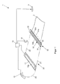
- FIG. 1 shows in a first embodiment of the invention, a rotating gripper system 1 for the transport of printing sheets 2 in a boom of a sheet-fed offset printing press (hereinafter "printing press").
- a control device 10 for controlling the gripper system 1 a gripper system guide 20 with two spaced apart guides in the form of gripper chains 21, 22, and a plurality of gripper carriage 30 (shown here only one), each consisting of a fiber-reinforced plastic material gripper system body 31 have.
- These are coupled to the gripper chains 21, 22 and are moved along a gripper chain path or an orbit of the gripper system 1.
- the in FIG. 1 shown gripper carriage 30 has a predetermined width over which the gripper system body 31 extends with a predetermined length.
- an actuator assembly 32 Integrated into the fiber structure of the gripper system body 31 is an actuator assembly 32 having a plurality of actuators in the form of piezofibre ceramic fibers 32a interconnected in one layer across the entire width of the gripper carriage 30 along the length of the gripper system body 31.
- the gripper system body 31 is formed so that when the actuator assembly 32 is not activated, it has a slight deflection (as exaggerated by the dashed curve line 31 a indicated), so that in operation on a of the gripper system body 31 transported sheet 2 a concave deformation is effected.
- the actoric action of the ceramic piezo fibers 32a causes stiffening of the fiber reinforced plastic material of the gripper system body 31 and stretching thereof.
- a receiver structure 33 is integrated, via which a control of the actuator assembly 32 (or of their ceramic piezo fibers 32a) and their power supply is ensured.
- the receiver structure 33 has an energy store in the form of a battery / capacitor combination, conductor tracks which connect the battery / capacitor combination with the piezo fibers 32a, a radio-controlled switch, which is connected between the battery / capacitor combination and the piezo fibers 32a and which can be actuated by the control device 10 by radio for activating / deactivating the actuator arrangement 32, and a coil system 33a which is used for inductive charging of the battery / capacitor Combination in the gripper carriage 30 is integrated.
- the control device 10 has a radio device (not shown) for driving the switch of the receiver structure 33 of the gripper carriage 30, transmission means in the form of an induction unit 11 for charging the battery / capacitor combination of the receiver structure 33, a detector 12, via which the position of the gripper carriage 30th or the position of the front transverse edges of the signatures 2 can be detected, as well as a position determining device 13, via which a current rotational phase position of the gripper system 1 can be detected.
- the induction unit 11, the detector 12 and the position determining device 13 are coupled to the control device 10 via lines.
- a control station 3 for an operator of the printing machine is coupled to the control device 10, wherein influence can be taken on the operation of the control device via the control station 3.
- the control device 10 can generate a trigger signal which is transmitted by radio to the switch in the receiver structure 33 of the gripper carriage 30, so that stiffening / stiffening occurs at defined times of the gripper system body 31 is effected.
- a coil system 11 a is integrated, which, when a gripper carriage 30 passes over or passes through the induction unit 11, cooperates inductively with the integrated in the gripper carriage 30 coil system 33 a of the receiver structure 33, so that in the coil system 33 a of the gripper carriage 30 current to Charging the battery / capacitor combination is induced.
- the control device 10 is set up or configured by a combination of software and hardware in such a way that during operation of the gripper system 1 by selection by the control station 3, the stiffening of the gripper system body 31 during the circulation in sections along the orbit of the gripper system 1 or over the entire orbit of Gripper system 1 can be done away.
- control device 10 is configured such that during operation of the gripper system 1, the stiffening of the gripper system body 31 takes place at a time when a signature 2 is transferred from a last sheet-guiding cylinder (not shown) of the sheet-fed press to the gripper system body 31.
- a last sheet-guiding cylinder not shown
- the control device 10 is configured such that during operation of the gripper system 1, the stiffening of the gripper system body 31 takes place at a time when a signature 2 is transferred from a last sheet-guiding cylinder (not shown) of the sheet-fed press to the gripper system body 31.
- control device 10 is further arranged such that during operation of the gripper system 1, the stiffening of the gripper system body 31 takes place at deflection points 23 of the orbit of the gripper system 1 in the boom.
- an ideal guideway of the gripper system body 31 is ensured at the deflection points 23 and also ensures the reliability of the gripper system 1 according to the invention, since the operator, who may be behind such a deflection point 23, better due to the there increased mechanical stability of the gripper system body 31 against defect Injury is protected.
- a work program for the gripper system 1 is selected by the operator at the control station 3, which corresponds to the above-preferred configuration in this example.
- the gripper system 1 When rotating the gripper chains 21, 22 of the control device 10 by the detector 12 and the position determining device 13 is constantly provided information or measurement data on the rotational phase position of the gripper chains 21, 22 and the position of the gripper carriage 30.
- the gripper system 1 is automatically synchronized to the printing units (not shown) of the printing press on the basis of the measurement data. If the gripper carriage 30 run over the induction unit 11 during its rotation, the battery / capacitor combination is charged inductively. In this connection, it should be noted that the battery of the battery / capacitor combination according to this embodiment is precharged.
- a trigger signal is sent by the control device 10 by radio to the switch of the receiver structure 33 of the gripper carriage 30, so that the switch is closed and thus voltage is applied to the piezo fibers 32a of the actuator assembly 32.
- the gripper system body 31 of the respective gripper carriage 30 is stiffened and brought in an optimal position to the area of the sheet transfer.
- the gripper system body 31 on which a plurality of grippers (not shown) are provided, which are radio-coupled to the controller 10 and are operable by the controller 10 separately or in common to grasp / release a signature 2, can be actuated from the latter sheet-guiding cylinder of the printing press output sheet 2 easily take or take.
- the control device After taking over the printed sheet 2, the control device transmits by radio another trigger signal to the switch of the receiver structure 33 of the gripper carriage 30, so that the switch is opened and thus no voltage is applied to the piezo fibers 32a of the actuator assembly 32.
- the gripper system body 31 easily sag in the curved line 31 a shown in dashed lines, so that the printed sheet 2 a concave shape is impressed.
- the gripper carriage 30 arrives at the position of the delivery, the grippers of the gripper system body 31 are opened and the signature 2 is deposited on a delivery stack. The gripper carriage 30 then continues until it arrives at one of the Umlenkpunke 23 of the gripper system 1. Shortly before the deflection point 23, the control device 10 again sends a trigger signal to the switch of the receiver structure 33 of the respective gripper carriage 30, so that the switch is closed and thus voltage is applied to the piezo fibers 32a of the actuator assembly 32. As a result, the gripper system body 31 is stiffened shortly before the deflection point 23 and can thus be moved through it in an optimal guiding position.
- control device 10 After passing the deflection point 23, the control device 10 again sends a trigger signal to the switch of the receiver structure 33 of the respective gripper carriage 30, so that the switch is opened and thus no voltage is applied to the piezo fibers 32a of the actuator assembly 32.
- the gripper carriage 30 passes before a renewed reaching the area of the sheet transfer, a second deflection point 23, at which in the manner described above again a stiffening and subsequent stiffening of the gripper system body 31 takes place.
- the stiffening of the gripper system body 31 after the deflection points 23 are used here mainly to save energy and can also be omitted if desired.
- the stiffeners of the gripper system body 31 at the quality or safety-relevant positions such as the area of the pressure sheet transfer and the deflection points 23.
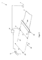
- FIG. 2 a gripper system 1 'according to a second embodiment of the invention described.
- Such a gripper system 1 'for the transport of signatures 2' in the delivery of the printing press has a gripper system guide 20 'with two at a first distance A1 arranged guides in the form of gripper chains 21', 22 'and more on the gripper chains 21', 22nd 'held gripper carriage 30' (in FIG. 2 only one gripper carriage 30 'is shown), which are coupled to the gripper chains 21', 22 'and can be moved in a manner known per se along a gripper chain path or an orbit of the gripper system 1'.
- the gripper system 1 'further comprises a control device 10' for controlling the gripper system 1 '.
- the gripper carriages 30 'each have a gripper system body 31' having a flexible structure and a predetermined length, the length being dimensioned such that the gripper system body 31 'bridging the first distance A1 by a predetermined amount or as indicated by the dashed curve line 31a'. exaggerated indicated sags.
- the gripper system body 31 ' has a plurality of grippers, not shown, which are radio-coupled to the controller 10' and are operable by the controller 10 'separately or in common to grasp / release a signature 2'.
- the control device 10 'therefore has a radio device (not shown) for driving the gripper of the gripper carriage 30', a detector 12 ', via which the position of the gripper carriage 30' or the position of the front transverse edges of the signatures 2 'can be detected, as well a position determining device 13 ', via which a current rotational phase position of the gripper system 1' can be detected.
- the detector 12 'and the position determining device 13' are coupled to the controller 10 'via lines.
- a control station 3 ' is coupled to the control device 10' for an operator of the printing machine, it being possible to influence the operation of the control device 10 'via the control station 3'.
- control device 10 By means of the information or measured values provided by the detector 12 'and the position-determining device 13', the control device 10 'can control the grippers of the gripper carriage 30' with exact position.
- the gripper chains 21 ', 22' have in the region of a sheet transfer and at deflection points 23 'to a second distance A2, which is so much larger than the first distance A1 dimensioned that the gripper system body 31' in the sheet transfer area and at the deflection points 23rd 'is stretched and stiffened by it.
- lateral stops of the gripper chains 21 ', 22' are displaced laterally outwards in the area of the sheet transfer and at the deflection points 23 '.
- the gripper chains 1' the first distance A1 from each other, so that here the gripper system body 31 'according to the curved line 31 a' slightly sags and a sheet transported by him 2 'during transport a concave Imprint form.
- the stiffeners / stiffeners of the respective gripper system bodies 31' are effected automatically and predetermined by the guidance of the gripper chains 21 ', 22'.
- the time sequence of the stiffeners / stiffeners along the orbit of the gripper system 1 ' substantially corresponds to that of the first embodiment of the invention and will therefore not be explained again in detail.
- the second embodiment can be dispensed with a stiffening in the area between the deflection points 23 '(without sheet transfer), so that the gripper system body 31' are entsteift only in an area after sheet takeover and before the first deflection point 23 'to the signatures 2 'to impress the concave shape.
Landscapes
- Engineering & Computer Science (AREA)
- Mechanical Engineering (AREA)
- Feeding Of Articles By Means Other Than Belts Or Rollers (AREA)
- Discharge By Other Means (AREA)
Applications Claiming Priority (1)
| Application Number | Priority Date | Filing Date | Title |
|---|---|---|---|
| DE102007061387.5A DE102007061387B4 (de) | 2007-12-19 | 2007-12-19 | Umlaufendes Greifersystem für den Bogentransport und Verfahren zum Betreiben dessen |
Publications (1)
| Publication Number | Publication Date |
|---|---|
| EP2072436A2 true EP2072436A2 (fr) | 2009-06-24 |
Family
ID=40469792
Family Applications (1)
| Application Number | Title | Priority Date | Filing Date |
|---|---|---|---|
| EP08171751A Withdrawn EP2072436A2 (fr) | 2007-12-19 | 2008-12-16 | Système de pinces mobiles pour le transport de feuilles |
Country Status (2)
| Country | Link |
|---|---|
| EP (1) | EP2072436A2 (fr) |
| DE (1) | DE102007061387B4 (fr) |
Cited By (1)
| Publication number | Priority date | Publication date | Assignee | Title |
|---|---|---|---|---|
| EP4541591A1 (fr) * | 2023-10-19 | 2025-04-23 | Heidelberger Druckmaschinen AG | Pince pour matière à imprimer en forme de feuille |
Families Citing this family (2)
| Publication number | Priority date | Publication date | Assignee | Title |
|---|---|---|---|---|
| DE102010002771B4 (de) | 2010-03-11 | 2019-10-17 | Koenig & Bauer Ag | Auslage einer bogenverarbeitenden Machine und Verfahren zum Fördern von Bogen in der Auslage |
| DE102019123579B4 (de) * | 2019-09-03 | 2022-12-08 | Koenig & Bauer Ag | Vorrichtung zum Transport von Bogen in einer bogenverarbeitenden Maschine |
Citations (3)
| Publication number | Priority date | Publication date | Assignee | Title |
|---|---|---|---|---|
| US2198385A (en) | 1938-06-07 | 1940-04-23 | Harris Seybold Potter Co | Sheet conveyer mechanism |
| DE4221580C2 (de) | 1992-07-01 | 2001-02-01 | Heidelberger Druckmasch Ag | Halteleiste einer papierbogenverarbeitenden Maschine |
| DE20313394U1 (de) | 2003-08-29 | 2003-11-06 | MAN Roland Druckmaschinen AG, 63075 Offenbach | Auslegevorrichtung für eine Bogenverarbeitungsmaschine |
Family Cites Families (6)
| Publication number | Priority date | Publication date | Assignee | Title |
|---|---|---|---|---|
| JP3339515B2 (ja) | 1993-08-12 | 2002-10-28 | 株式会社小森コーポレーション | 枚葉印刷機の紙搬送装置 |
| DE29506484U1 (de) | 1995-04-15 | 1995-07-20 | Woschnik + Partner Maschinenbau GmbH, 41063 Mönchengladbach | Greifereinrichtung für bogenverarbeitende Maschinen |
| DE102005021770A1 (de) | 2005-05-11 | 2006-11-16 | Man Roland Druckmaschinen Ag | Bogenführende Trommel für eine Druckmaschine |
| DE102007040694B4 (de) | 2006-09-20 | 2018-07-05 | Heidelberger Druckmaschinen Ag | Vorrichtung zur Umstellung der Betriebsart von Schön- auf Schön- und Widerdruck in einer Bogen verarbeitenden Maschine |
| DE102006061431A1 (de) | 2006-12-23 | 2008-06-26 | Koenig & Bauer Aktiengesellschaft | Vorrichtung zur Lagekorrektur von Bogen |
| DE102007033932A1 (de) | 2007-07-20 | 2009-01-22 | Manroland Ag | Greifersystem für eine Bogendruckmaschine |
-
2007
- 2007-12-19 DE DE102007061387.5A patent/DE102007061387B4/de not_active Expired - Fee Related
-
2008
- 2008-12-16 EP EP08171751A patent/EP2072436A2/fr not_active Withdrawn
Patent Citations (3)
| Publication number | Priority date | Publication date | Assignee | Title |
|---|---|---|---|---|
| US2198385A (en) | 1938-06-07 | 1940-04-23 | Harris Seybold Potter Co | Sheet conveyer mechanism |
| DE4221580C2 (de) | 1992-07-01 | 2001-02-01 | Heidelberger Druckmasch Ag | Halteleiste einer papierbogenverarbeitenden Maschine |
| DE20313394U1 (de) | 2003-08-29 | 2003-11-06 | MAN Roland Druckmaschinen AG, 63075 Offenbach | Auslegevorrichtung für eine Bogenverarbeitungsmaschine |
Non-Patent Citations (1)
| Title |
|---|
| "Handbuch Helmut Teschner", 1989, FACHSCHRIFTEN-VERLAG, article "Offsetdrucktechnik", pages: 466 |
Cited By (1)
| Publication number | Priority date | Publication date | Assignee | Title |
|---|---|---|---|---|
| EP4541591A1 (fr) * | 2023-10-19 | 2025-04-23 | Heidelberger Druckmaschinen AG | Pince pour matière à imprimer en forme de feuille |
Also Published As
| Publication number | Publication date |
|---|---|
| DE102007061387B4 (de) | 2021-09-02 |
| DE102007061387A1 (de) | 2009-06-25 |
Similar Documents
| Publication | Publication Date | Title |
|---|---|---|
| EP0907515B1 (fr) | Systeme de transport de feuille pour une presse rotative | |
| EP1136263A2 (fr) | Dispositif pour transporter une feuille pour une machine d'impression rotative | |
| DE10141589A1 (de) | Verfahren zum Betreiben einer Bogen verarbeitenden Maschine und Maschine zur Bearbeitung von Bogen | |
| EP4209351B1 (fr) | Machine de traitement de feuilles, utilisation de la machine de traitement de feuilles, procédé de transport de feuilles et utilisation d'éléments conducteurs de feuilles contenant des dispositifs de désionisation | |
| DE19722376A1 (de) | Bogentransportsystem für eine Rotationsdruckmaschine | |
| EP1541510B1 (fr) | Dispositif pour amener des feuilles par une imprimeuse | |
| EP2072254A2 (fr) | Cylindre de transport doté d'un dispositif de préhension mobile | |
| WO1997045267A1 (fr) | Systeme de transport de feuille pour une presse rotative | |
| DE102007061387B4 (de) | Umlaufendes Greifersystem für den Bogentransport und Verfahren zum Betreiben dessen | |
| DE102015209695B4 (de) | Bogenführungszylinder und Verfahren zur Formatverstellung eines Bogenführungszylinders | |
| EP4577413B1 (fr) | Rotative à feuilles comportant une unité d'électrode | |
| DE10134836B4 (de) | Ausleger für eine bogenverarbeitende Maschine, insbesondere für eine Bogendruckmaschine | |
| DE102012222525B4 (de) | Auslage und Verfahren zum Transportieren von Bogen in einer Auslage | |
| WO2025061417A1 (fr) | Presse d'impression alimentée en feuilles avec dispositif de charge et décharge | |
| DE102023125603A1 (de) | Bogendruckmaschine mit Aufladungseinrichtung am Gegendruckzylinder und Entladungseinrichtung | |
| DE102015216870B4 (de) | Maschinenanordnung mit mehreren Bearbeitungsstationen zum sequentiellen Bearbeiten mehrerer bogenförmiger Substrate | |
| DE102007033931A1 (de) | Greifersystem für eine Bogendruckmaschine | |
| DE10239709B4 (de) | Einrichtung zur Ablage von Bogen im Ausleger einer bogenverarbeitenden Maschine | |
| EP2017080A2 (fr) | Système de pinces pour une presse d'impression de feuilles | |
| DE102015216877B4 (de) | Verfahren zum sequentiellen Zuführen mehrerer Bogen zu einer diese Bogen jeweils bearbeitenden Bearbeitungsstation | |
| DE3509696A1 (de) | Einrichtung in bogenauslegern | |
| DE102008043754A1 (de) | Bogenführungssystem für eine Bogen verarbeitende Druck-, Veredelungs- oder Weiterverarbeitungsmaschine | |
| DE102023104096A1 (de) | Bogenrotationsdruckmaschine mit Elektrodeneinheit und Halteelement | |
| DE102015216873B4 (de) | Verfahren zum Betrieb einer einzelne bogenförmige Substrate einer Bearbeitungsstation sequentiell zuführenden Transportvorrichtung | |
| DE102015216871B4 (de) | Maschinenanordnung zum sequentiellen Bearbeiten mehrerer bogenförmiger jeweils eine Vorderseite und eine Rückseite aufweisender Substrate |
Legal Events
| Date | Code | Title | Description |
|---|---|---|---|
| PUAI | Public reference made under article 153(3) epc to a published international application that has entered the european phase |
Free format text: ORIGINAL CODE: 0009012 |
|
| AK | Designated contracting states |
Kind code of ref document: A2 Designated state(s): AT BE BG CH CY CZ DE DK EE ES FI FR GB GR HR HU IE IS IT LI LT LU LV MC MT NL NO PL PT RO SE SI SK TR |
|
| AX | Request for extension of the european patent |
Extension state: AL BA MK RS |
|
| RIC1 | Information provided on ipc code assigned before grant |
Ipc: B65H 29/04 20060101AFI20111028BHEP |
|
| STAA | Information on the status of an ep patent application or granted ep patent |
Free format text: STATUS: THE APPLICATION HAS BEEN WITHDRAWN |
|
| RIC1 | Information provided on ipc code assigned before grant |
Ipc: B65H 29/04 20060101AFI20111213BHEP |
|
| 18W | Application withdrawn |
Effective date: 20111214 |
|
| RIC1 | Information provided on ipc code assigned before grant |
Ipc: B65H 29/04 20060101AFI20111219BHEP |