EP2073191B1 - Abbildungssystem - Google Patents
Abbildungssystem Download PDFInfo
- Publication number
- EP2073191B1 EP2073191B1 EP08172472A EP08172472A EP2073191B1 EP 2073191 B1 EP2073191 B1 EP 2073191B1 EP 08172472 A EP08172472 A EP 08172472A EP 08172472 A EP08172472 A EP 08172472A EP 2073191 B1 EP2073191 B1 EP 2073191B1
- Authority
- EP
- European Patent Office
- Prior art keywords
- display region
- foveal
- data
- operable
- image
- Prior art date
- Legal status (The legal status is an assumption and is not a legal conclusion. Google has not performed a legal analysis and makes no representation as to the accuracy of the status listed.)
- Active
Links
Images

Classifications
-
- H—ELECTRICITY
- H04—ELECTRIC COMMUNICATION TECHNIQUE
- H04N—PICTORIAL COMMUNICATION, e.g. TELEVISION
- H04N5/00—Details of television systems
-
- H—ELECTRICITY
- H04—ELECTRIC COMMUNICATION TECHNIQUE
- H04N—PICTORIAL COMMUNICATION, e.g. TELEVISION
- H04N13/00—Stereoscopic video systems; Multi-view video systems; Details thereof
- H04N13/10—Processing, recording or transmission of stereoscopic or multi-view image signals
- H04N13/106—Processing image signals
- H04N13/172—Processing image signals image signals comprising non-image signal components, e.g. headers or format information
- H04N13/178—Metadata, e.g. disparity information
-
- G—PHYSICS
- G02—OPTICS
- G02B—OPTICAL ELEMENTS, SYSTEMS OR APPARATUS
- G02B6/00—Light guides; Structural details of arrangements comprising light guides and other optical elements, e.g. couplings
- G02B6/04—Light guides; Structural details of arrangements comprising light guides and other optical elements, e.g. couplings formed by bundles of fibres
- G02B6/06—Light guides; Structural details of arrangements comprising light guides and other optical elements, e.g. couplings formed by bundles of fibres the relative position of the fibres being the same at both ends, e.g. for transporting images
-
- G—PHYSICS
- G09—EDUCATION; CRYPTOGRAPHY; DISPLAY; ADVERTISING; SEALS
- G09G—ARRANGEMENTS OR CIRCUITS FOR CONTROL OF INDICATING DEVICES USING STATIC MEANS TO PRESENT VARIABLE INFORMATION
- G09G3/00—Control arrangements or circuits, of interest only in connection with visual indicators other than cathode-ray tubes
- G09G3/001—Control arrangements or circuits, of interest only in connection with visual indicators other than cathode-ray tubes using specific devices not provided for in groups G09G3/02 - G09G3/36, e.g. using an intermediate record carrier such as a film slide; Projection systems; Display of non-alphanumerical information, solely or in combination with alphanumerical information, e.g. digital display on projected diapositive as background
- G09G3/002—Control arrangements or circuits, of interest only in connection with visual indicators other than cathode-ray tubes using specific devices not provided for in groups G09G3/02 - G09G3/36, e.g. using an intermediate record carrier such as a film slide; Projection systems; Display of non-alphanumerical information, solely or in combination with alphanumerical information, e.g. digital display on projected diapositive as background to project the image of a two-dimensional display, such as an array of light emitting or modulating elements or a CRT
-
- H—ELECTRICITY
- H04—ELECTRIC COMMUNICATION TECHNIQUE
- H04N—PICTORIAL COMMUNICATION, e.g. TELEVISION
- H04N13/00—Stereoscopic video systems; Multi-view video systems; Details thereof
- H04N13/30—Image reproducers
- H04N13/332—Displays for viewing with the aid of special glasses or head-mounted displays [HMD]
- H04N13/344—Displays for viewing with the aid of special glasses or head-mounted displays [HMD] with head-mounted left-right displays
-
- H—ELECTRICITY
- H04—ELECTRIC COMMUNICATION TECHNIQUE
- H04N—PICTORIAL COMMUNICATION, e.g. TELEVISION
- H04N23/00—Cameras or camera modules comprising electronic image sensors; Control thereof
- H04N23/90—Arrangement of cameras or camera modules, e.g. multiple cameras in TV studios or sports stadiums
-
- G—PHYSICS
- G09—EDUCATION; CRYPTOGRAPHY; DISPLAY; ADVERTISING; SEALS
- G09G—ARRANGEMENTS OR CIRCUITS FOR CONTROL OF INDICATING DEVICES USING STATIC MEANS TO PRESENT VARIABLE INFORMATION
- G09G2340/00—Aspects of display data processing
- G09G2340/04—Changes in size, position or resolution of an image
- G09G2340/0407—Resolution change, inclusive of the use of different resolutions for different screen areas
Definitions
- This disclosure generally relates to imaging systems, and more particularly, to an imaging system operable to generate an image with multiple display regions.
- Visual displays typically include a number of lighting elements that form pixels of an image.
- the lighting elements may be arranged in a N number of rows by a M number of columns to form an N*M image.
- Common types of visual displays may include cathode ray tubes (CRTs) or liquid crystal displays (LCDs).
- CTRs cathode ray tubes
- LCDs liquid crystal displays
- An example of a visual display with non-uniform pixel density forming a foveated display can be found in US 2004/0227703 .
- an imaging system includes a processing system and a display generator.
- the processing system is operable to process a signal received from a camera to yield foveal data for a foveal display region and outer data for an outer display region.
- the outer data have a reduced pixel density with respect to the pixel density of the foveal data.
- the display generator is operable to generate the foveal display region from the foveal data according to a 1:n mapping ratio, and generate the outer display region from the outer data according to a 1:m mapping ratio, where m is greater than n.
- Certain embodiments of the disclosure may provide advantages. Certain embodiments may more efficiently use image data by providing a foveal display region with a higher pixel density and an outer display region with a lower pixel density. The efficient use of image data may allow for increased compression of data. Certain embodiments may provide greater resolution at the foveal display region and greater field-of-view at the outer display region.
- Imaging systems may comprise visual displays that display images generated from signal received from video cameras. These imaging systems may provide various benefits over view by the naked eye. For example, imaging systems, such as surveillance systems, may provide images of remote locations. As another example, imaging systems may receive signals from infrared cameras to generate images of thermal environments.
- Visual displays may include multiple lighting elements that form pixels of an image.
- the quality of the image produced by the visual display may be proportional to the pixel density of the image.
- Pixel density generally refers to the quantity of pixels of an image per the area of the image.
- Visual displays may be limited, however, in the density of lighting elements that generate the pixilated image. Thus, providing uniform pixel density across a full field of view may difficult to achieve.
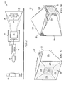
- FIGURE 1 shows one embodiment of an imaging system 10 according to the teachings of the present disclosure.
- Imaging system 10 includes a camera 12 coupled to a display generator 14 through a processing circuit 16 as shown.
- Camera 12 is operable to generate an electrical signal that represents light reflected or emitted from an object 18.
- Processing circuit 16 is operable to process the electrical signal for use by display generator 14.
- Display generator 14 is operable generate an image 28 from the processed signal received from processing circuit 16.
- Image 28 includes foveal display region 24 and outer display region 26.
- imaging system 10 may provide advantages. Certain embodiments may more efficiently use image data by providing a foveal display region 24 with a higher pixel density and an outer display region 26 with a lower pixel density. Certain embodiments may provide greater resolution at foveal display region 24 and greater field-of-view at outer display region 26.
- Processing circuit 16 may be any suitable device that processes the electrical signal from one or more cameras 12 into a form suitable for use by display generator 14.
- processing circuit 16 comprises a processor executing instructions stored in a memory.
- Memory may include any one or combination of volatile memory elements, such as random access memory (RAM), dynamic random access memory (DRAM), static random access memory (SRAM), and nonvolatile memory elements, such as read only memory (ROM), erasable programmable read only memory (EPROM), electronically erasable programmable read only memory (EEPROM), programmable read only memory (PROM), tape, compact disc read only memory (CD-ROM), disk, diskette, cartridge, or the like.
- Processing circuit 16 processes electrical signals received from camera 12 to yield image 28 that includes foveal display region 24 and outer display region 26.
- processing circuit 16 is coupled to multiple cameras 12 that detect light from object 18 at various field-of-views that may be used to process foveal display region 24 and outer display region 26. In another embodiment, processing circuit 16 is coupled to a single camera 12 with multiple apertures that detect light from object 18 at multiple field-of-views. In another embodiment, processing circuit 16 processes signals from a single camera 12 to reduce the pixel density at outer display region 26 relative to foveal display region 24.
- Display generator 14 may be any device that generates image 28 having a foveal display region 24 and an outer display region 26.
- display generator 14 includes a spatial light generator 20 optically coupled to a fiber optic coupler 22.
- Spatial light generator 20 may be any suitable device that generates light that form pixels according to the electrical signal provided by camera 12.
- spatial light generator 20 includes a cathode ray tube (CRT) or a liquid crystal display (LCD).
- spatial light generator 20 includes a light source and a light modulating device, such as a digital micro-mirror device (DMD), that modulates light from the light source.
- DMD digital micro-mirror device
- Fiber optic coupler 22 is operable to form a foveal display region 24 and an outer display region 26. Fiber optic coupler 22 is described in more detail with reference to FIGURES 2A and 2B .
- Image 28 may be formed on any suitable two-dimensional or three-dimensional surface. In the particular embodiment shown, image 28 is projected onto an external surface. In other embodiments, image 28 may be viewed from a two-dimensional surface of fiber optic coupler 22.
- Display generator 14 may be used with any suitable imaging platform.
- an imaging platform may be a head-mounted display, such as a helmet, that maintains display generator 14 in a fixed position in front of the user's eyes.
- Display generator 14 configured on a head-mounted display may maintain foveal display region 24 in alignment with the foveal portion of the user's eyes.
- an imaging platform may be a surveillance system in which foveal display region 24 may be used to enhance visual quality of a specified portion of object 18, while maintaining a relatively wide field-of-view.
- the fovea of the human eye detects visual information with greater precision than other portions of the eye.
- the fovea yields a foveal portion of the eye's field-of-view that is more precise. In most cases, the foveal portion is centrally located within the field-of-view.
- the foveal display region 24 of the image 28 may provide more visual information for the fovea.
- Outer display region 26 displays peripheral information around the foveal display region 24 with less visual information.
- Image 28 may have a field-of-view based upon its distance from the eyes of the user.
- image 28 may have a field-of-view of approximately 45 degrees in width by 36 degrees in height relative to the eyes of the user.
- the field-of-view of image 28 may have any suitable dimensions, such as a width of less than 30, 30 to 60 degrees, or greater than 60 degrees and a height of less than 20, 20 to 50 degrees, or greater than 50 degrees.
- the field-of-view may have an aspect ratio suitable for viewing image 28.
- Foveal display region 24 may form any portion of image 28.
- foveal display region 24 may comprise 18 degrees (width) by 14.4 degrees (height) of the field-of-view with the outer display region 26 comprising 45 degrees (width) by 36 degrees (height) field-of-view relative to the eyes of the user.
- foveal display region 24 may be approximately 40 percent of the field-of-view of outer display region 26.
- foveal display region 24 may form any portion of image 28 that may range from less than 30 percent, 30 percent to 50 percent, or greater than 50 percent of the viewing area of image 28.
- FIGURES 2A and 2B show a front perspective view and a rear perspective view, respectively, of one embodiment of fiber optic coupler 22.
- Fiber optic coupler 22 includes a section of first lighting elements 22a that transmit light generated by spatial light generator 20 to form foveal display region 24.
- Fiber optic coupler 22 includes four sections of second lighting elements 22b that transmit light generated by spatial light generator 20 to form outer display region 26 having four sub-regions that are contiguous with foveal display region 24.
- outer display region 26 may have any quantity and shape of sub-regions that are contiguous with foveal display region 24.
- lighting elements 22a have generally constant cross-sections.
- the cross-sections of second lighting elements 22b expand as lighting elements 22b extend from spatial light generator 20 to outer display region 26.
- the density of pixels of foveal display region 24 may be greater than the density of pixels of outer display region 26.
- outer display region 26 may have any suitable magnification relative to foveal display region 24, such as less than 2:1, 2:1 to 6:1, or greater than 6:1.
- display generator 14 may have any suitable combination of pixel densities, such as a pixel density of foveal display region 24 of less than .20 milli-radians, .20 to .50 milli-radians, or greater than .50 milli-radians and a pixel density of outer display region 26 pixel density of less than 1.0 milli-radians, 1.0 to 1.6 milli-radians, or greater than 1.6 milli-radians.
- FIGURES 3A and 3B show front and side views, respectively, of fiber optic coupler 22 of FIGURES 2A and 2B .
- the cross-section of a lighting element from an input end to an output end may affect the size of the resulting pixel.
- an expanding cross-section may yield a larger pixel, and a constant cross-section may yield a pixel of the same size.
- the effect that a light element has on the size of the resulting pixel may be described as a mapping ratio of 1:x, where 1 represents the input light and x represents the output light.
- first lighting elements 22a may have a 1-to-n mapping ratio
- second lighting elements 22b may have a 1-to-m mapping ratio, where m > n.
- Parameters m and n may have any suitable values.
- m may be approximately 1, 1 to 4, or 4 or greater
- n may be approximately 1, 1 to 2, or 2 or greater.
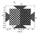
- FIGURE 4 shows example image data 118
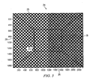
- FIGURE 5 shows image 28 that may be generated from image data 118
- image data 118 represents a checkerboard pattern and includes foveal data 124 and outer data 126.
- Foveal data 124 is used to generate foveal display region 24 of image 28
- outer data 126 is used to generate outer display region 26 of image 28. Accordingly, foveal data 124 yields a pixel density that is less than the pixel density yielded by outer data 126.
- processing system 16 may process foveal data 124 and outer data 126 to yield the differing pixel densities.
- lighting elements 22b increase the relative size of outer display region 26 relative to foveal display region 24.
- imaging system 10 may be integrated or separated.
- the operations of processing circuit 16 may be integrated with camera 12.
- the operations of imaging system 10 may be performed by more, fewer, or other components.
- spatial light generator 20 may have an integral foveal display region 24 and outer display region 26 such that an independent fiber optic coupler 22 is not necessary.
- operations of processing circuit 16 may be performed using any suitable logic comprising software, hardware, and/or other logic. As used in this document, "each" refers to each member of a set or each member of a subset of a set.
- Certain embodiments of the disclosure may provide advantages. Certain embodiments may more efficiently use image data by providing a foveal display region with a higher pixel density and an outer display region with a lower pixel density. The efficient use of image data may allow for increased compression of data. Certain embodiments may provide greater resolution at the foveal display region and greater field-of-view at the outer display region.
Landscapes
- Engineering & Computer Science (AREA)
- Physics & Mathematics (AREA)
- Multimedia (AREA)
- Signal Processing (AREA)
- General Physics & Mathematics (AREA)
- Theoretical Computer Science (AREA)
- Optics & Photonics (AREA)
- Computer Hardware Design (AREA)
- Library & Information Science (AREA)
- Controls And Circuits For Display Device (AREA)
- Studio Devices (AREA)
- Control Of Indicators Other Than Cathode Ray Tubes (AREA)
- Image Processing (AREA)
- Devices For Indicating Variable Information By Combining Individual Elements (AREA)
- Investigating Materials By The Use Of Optical Means Adapted For Particular Applications (AREA)
- Eye Examination Apparatus (AREA)
- Vehicle Body Suspensions (AREA)
- Iron Core Of Rotating Electric Machines (AREA)
Claims (15)
- Abbildungssystem (10), aufweisend:ein Bildverarbeitungssystem (16) betriebsfähig zum:Verarbeiten eines oder mehrerer von einer oder mehreren korrespondierenden Kameras (12) empfangener Signale zum Erbringen fovieler Daten (124) für eine foviele Anzeigeregion (24) eines Bilds (28) und äußerer Daten (126) für eine äußere Anzeigeregion (26) des Bilds (28), wobei eine äußere Pixeldichte der äußeren Daten (126) geringer ist als die foviele Pixeldichte der fovielen Daten (124), undeinen Anzeigegenerator (14) betriebsfähig zum:Erzeugen der fovielen Anzeigeregion (24) aus den fovielen Daten (124) unter Benutzung von Beleuchtungselementen (22a) mit einem konstanten Querschnitt entsprechend einem 1:1-Abbildungsverhältnis, undErzeugen der äußeren Anzeigeregion (26) aus den äußeren Daten (126) unter Benutzung von Beleuchtungselementen (22b) mit einem expandierenden Querschnitt entsprechend einem 1:m-Abbildungsverhältnis, wobei m größer als 1 ist.
- Abbildungssystem (10) nach Anspruch 1, wobei der Anzeigegenerator (14) einen faseroptischen Koppler (22) aufweist, wobei der faseroptische Koppler (22) aufweist:mehrere erste Beleuchtungselemente (22a), betriebsfähig zum Übertragen von Licht entsprechend dem 1:1-Abbildungsverhältnis, undmehrere zweite Beleuchtungselemente (22b), betriebsfähig zum Übertragen von Licht entsprechend dem 1:m-Abbildungsverhältnis.
- Abbildungssystem (10) nach Anspruch 1 oder 2, wobei die äußere Anzeigeregion (26) die foviele Anzeigeregion (24) im Wesentlichen umgibt,
und/oderdie foviele Anzeigeregion (24) vier Seiten aufweist, die äußere Anzeigeregion (26) vier Subregionen aufweist, wobei jede Subregion einer Seite der vier Seiten benachbart ist. - Abbildungssystem (10) nach einem der vorhergehenden Ansprüche, wobei der Anzeigegenerator (14) auf einer kopfbefestigten Anzeige konfiguriert ist, die betriebsfähig ist, um von einem Benutzer getragen zu werden, wobei die kopfbefestigte Anzeige betriebsfähig ist zum Aufrechterhalten des Bilds (28) an einer im Wesentlichen fixierten Position relativ zu wenigstens einem der Augen des Benutzers, wobei die foviele Anzeigeregion (24) und die äußere Anzeigeregion (26) ein horizontales Gesichtsfeld im Bereich von 30 Grad bis 60 Grad und ein vertikales Gesichtsfeld im Bereich von 20 Grad bis 50 Grad relativ zum Benutzer aufweisen.
- Abbildungssystem (10) nach einem der vorhergehenden Ansprüche, wobei m um einen Vergrößerungsfaktor im Bereich von 2 bis 6 größer als 1 ist,
und/oderdie foviele Anzeigeregion (24) ein Gesichtsfeld aufweist, das im Bereich von 30 Prozent bis 50 Prozent des Gesichtsfelds der äußeren Anzeigeregion (26) ist. - Abbildungssystem (10) nach einem der vorhergehenden Ansprüche, wobei
das Bildverarbeitungssystem (16) betriebsfähig ist zum:Verarbeiten eines ersten Subsatzes der Signale zum Erbringen der fovielen Daten (124), undVerarbeiten eines zweiten Subsatzes der Signale zum Erbringen der äußeren Daten (126). - Bildverarbeitungssystem (10) nach einem der vorhergehenden Ansprüche, wobei
das Bildverarbeitungssystem (16) betriebsfähig ist zum Verarbeiten des Signals zum Erbringen der fovielen Daten (124) und der äußeren Daten (126). - Abbildungsverfahren, aufweisend:Verarbeiten eines oder mehrerer von einer oder mehreren korrespondierenden Kameras (12) empfangener Signale zum Erbringen fovieler Daten (124) für eine foviele Anzeigeregion (24) eines Bilds (28) und äußerer Daten (126) für eine äußere Anzeigeregion (26) des Bilds (28), wobei eine äußere Pixeldichte der äußeren Daten (126) geringer ist als eine foviele Pixeldichte der fovielen Daten (124),Erzeugen der fovielen Anzeigeregion (24) aus den fovielen Daten (124) unter Benutzung von Beleuchtungselementen (22a) mit einem konstanten Querschnitt entsprechend einem 1: 1-Abbildungsverhältnis, undErzeugen der äußeren Anzeigeregion (26) aus den äußeren Daten (126) unter Benutzung von Beleuchtungselementen (22b) mit einem expandierenden Querschnitt entsprechend einem 1:m-Abbildungsverhältnis, wobei m größer als 1 ist.
- Verfahren nach Anspruch 8, wobei Erzeugen der fovielen Anzeigeregion (24) aufweist: Erzeugen der fovielen Anzeigeregion (24) unter Benutzung eines faseroptischen Kopplers (22), der Licht entsprechend dem 1:1-Abbildungsverhältnis überträgt, und Erzeugen der äußeren Anzeigeregion (26) aufweist Erzeugen der äußeren Anzeigeregion (26) unter Benutzung eines faseroptischen Kopplers (22), der Licht entsprechend dem 1:m-Abbildungsverhältnis überträgt.
- Verfahren nach Anspruch 8 oder 9, wobei das Erzeugen der äußeren Anzeigeregion (26) aufweist Erzeugen der die foviele Anzeigeregion (24) im Wesentlichen umgebenden äußeren Anzeigeregion (26),
und/oderdas Erzeugen der fovielen Anzeigeregion (24) aufweist Erzeugen der vier Seiten aufweisenden fovielen Anzeigeregion (24), und das Erzeugen der äußeren Anzeigeregion (26) aufweist Erzeugen der äußeren Anzeigeregion (26), welche vier Subregionen, die jeweils einer Seite der vier Seiten benachbart sind, aufweist. - Verfahren nach einem der vorhergehenden Ansprüche 8 bis 10, weiter aufweisend:das Aufrechterhalten des Bilds (28) an der im Wesentlichen fixierten Position weist auf Aufrechterhalten des Bilds (28) bei einem horizontalen Gesichtsfeld im Bereich von 30 Grad bis 60 Grad und einem vertikalen Gesichtsfeld im Bereich von 20 Grad bis 50 Grad relativ zu dem eine kopfbefestigte Anzeige aufweisenden Benutzer.
- Verfahren nach einem der vorhergehenden Ansprüche 8 bis 11, wobei das Erzeugen der äußeren Anzeigeregion (26) aufweist Erzeugen der äußeren Anzeigeregion (26) aus den äußeren Daten (126) entsprechend dem 1:m-Abbildungsverhältnis, wobei m um einen Vergrößerungsfaktor im Bereich von 2 bis 6 größer als 1 ist,
und/oderdas Erzeugen der fovielen Anzeigeregion aufweist Erzeugen der fovielen Anzeigeregion, die ein Gesichtsfeld aufweist, das im Bereich von 30 Prozent bis 50 Prozent der äußeren Anzeigeregion (26) liegt. - Verfahren nach einem der vorhergehenden Ansprüche 8 bis 12, weiter aufweisend:Verarbeiten eines ersten Subsatzes von mehreren Signalen aus mehreren Kameras (12) zum Erbringen der fovielen Daten (124) und Verarbeiten eines zweiten Subsatzes der mehreren Signale zum Erbringen der äußeren Daten (126).
- Verfahren nach einem der vorhergehenden Ansprüche 8 bis 13, weiter aufweisend:Verarbeiten eines Signals aus einer Kamera (12) zum Erbringen der fovielen Daten (124) und der äußeren Daten (126).
- Abbildungssystem (10) nach Anspruch 1,
wobei die äußere Anzeigeregion (26) die foviele Anzeigeregion (24) im Wesentlichen umgibt, und
wobei der Anzeigegenerator (14) auf einer kopfbefestigten Anzeige konfiguriert ist und den faseroptischen Koppler (22) aufweist, wobei der faseroptische Koppler (22) mehrere erste Beleuchtungselemente (22a), betriebsfähig zum Übertragen von Licht entsprechend einem 1:1-Abbildungsverhältnis, und mehrere zweite Beleuchtungselemente (22b), betriebsfähig zum Übertragen von Licht entsprechend einem 1:m-Abbildungsverhältnis, aufweist,wobei die foviele Anzeigeregion (24) unter Benutzung der mehreren ersten Beleuchtungselemente (22a) erzeugt wird, undwobei m um einen Vergrößerungsfaktor im Bereich von 2 bis 6 größer als 1 ist,ein Anzeigegenerator (14) betriebsfähig ist zum:Erzeugen der fovielen Anzeigeregion (14) aus den fovielen Daten (124) entsprechend einem 1:1-Abbildungsverhältnis,
undErzeugen der äußeren Anzeigeregion (26) aus den äußeren Daten (126) entsprechend einem 1:m-Abbildungsverhältnis, wobei m größer als 1 ist.
Applications Claiming Priority (2)
| Application Number | Priority Date | Filing Date | Title |
|---|---|---|---|
| US1555607P | 2007-12-20 | 2007-12-20 | |
| US12/338,624 US8314814B2 (en) | 2007-12-20 | 2008-12-18 | Imaging system |
Publications (2)
| Publication Number | Publication Date |
|---|---|
| EP2073191A1 EP2073191A1 (de) | 2009-06-24 |
| EP2073191B1 true EP2073191B1 (de) | 2011-08-31 |
Family
ID=40497642
Family Applications (1)
| Application Number | Title | Priority Date | Filing Date |
|---|---|---|---|
| EP08172472A Active EP2073191B1 (de) | 2007-12-20 | 2008-12-19 | Abbildungssystem |
Country Status (6)
| Country | Link |
|---|---|
| US (1) | US8314814B2 (de) |
| EP (1) | EP2073191B1 (de) |
| JP (2) | JP5265332B2 (de) |
| KR (1) | KR101543789B1 (de) |
| AT (1) | ATE522899T1 (de) |
| IL (1) | IL196078A (de) |
Families Citing this family (22)
| Publication number | Priority date | Publication date | Assignee | Title |
|---|---|---|---|---|
| JP4825561B2 (ja) * | 2006-03-29 | 2011-11-30 | 株式会社東芝 | 画像表示装置 |
| US8698859B2 (en) | 2010-10-19 | 2014-04-15 | Blackberry Limited | Display screen having regions of differing pixel density |
| US20120327116A1 (en) | 2011-06-23 | 2012-12-27 | Microsoft Corporation | Total field of view classification for head-mounted display |
| CN103959134B (zh) | 2011-11-24 | 2017-05-10 | 松下知识产权经营株式会社 | 头戴式显示器装置 |
| EP2958074A1 (de) * | 2014-06-17 | 2015-12-23 | Thomson Licensing | Verfahren und Anzeigevorrichtung mit Pixel-Verteilungsoptimierung |
| CN104469344B (zh) * | 2014-12-03 | 2017-03-01 | 北京智谷技术服务有限公司 | 光场显示控制方法和装置、光场显示设备 |
| EP3248052B8 (de) * | 2015-01-21 | 2020-09-09 | Tesseland LLC | Visuelle anzeige mit zeitmultiplex |
| US10475370B2 (en) * | 2016-02-17 | 2019-11-12 | Google Llc | Foveally-rendered display |
| US9986215B1 (en) * | 2017-03-23 | 2018-05-29 | Microsoft Technology Licensing, Llc | Laser scan beam foveated display |
| WO2018183405A1 (en) | 2017-03-27 | 2018-10-04 | Avegant Corp. | Steerable foveal display |
| CN111771179B (zh) | 2018-01-17 | 2025-05-27 | 奇跃公司 | 用于确定显示器与用户的眼睛之间的配准的显示系统和方法 |
| WO2019143844A1 (en) | 2018-01-17 | 2019-07-25 | Magic Leap, Inc. | Eye center of rotation determination, depth plane selection, and render camera positioning in display systems |
| US20190295503A1 (en) * | 2018-03-22 | 2019-09-26 | Oculus Vr, Llc | Apparatuses, systems, and methods for displaying mixed bit-depth images |
| WO2019221105A1 (ja) * | 2018-05-15 | 2019-11-21 | ソニーセミコンダクタソリューションズ株式会社 | 表示装置 |
| WO2020023542A1 (en) | 2018-07-24 | 2020-01-30 | Magic Leap, Inc. | Display systems and methods for determining registration between a display and eyes of a user |
| GB2578769B (en) | 2018-11-07 | 2022-07-20 | Advanced Risc Mach Ltd | Data processing systems |
| CA3122089A1 (en) | 2018-12-07 | 2020-06-11 | Avegant Corp. | Steerable positioning element |
| US11126261B2 (en) | 2019-01-07 | 2021-09-21 | Avegant Corp. | Display control system and rendering pipeline |
| GB2583061B (en) * | 2019-02-12 | 2023-03-15 | Advanced Risc Mach Ltd | Data processing systems |
| KR102649783B1 (ko) | 2019-03-29 | 2024-03-20 | 아브간트 코포레이션 | 도파관을 사용한 조향 가능한 하이브리드 디스플레이 |
| EP4062225A4 (de) | 2020-01-06 | 2023-12-27 | Avegant Corp. | Kopfmontiertes system mit farbspezifischer modulation |
| US11899215B1 (en) * | 2022-07-29 | 2024-02-13 | Htc Corporation | Head mounted display, display device and image display method thereof |
Family Cites Families (21)
| Publication number | Priority date | Publication date | Assignee | Title |
|---|---|---|---|---|
| JPS61169880A (ja) | 1985-01-23 | 1986-07-31 | 双葉電子工業株式会社 | 表示装置 |
| FR2626084A1 (fr) * | 1988-01-19 | 1989-07-21 | Labo Electronique Physique | Optique anamorphosante et dispositif anamorphoseur-desanamorphoseur |
| JPH0651142A (ja) * | 1992-02-26 | 1994-02-25 | Sanyo Electric Co Ltd | 光学素子及び光学素子を用いた画像表示装置 |
| EP0725939B1 (de) | 1992-03-13 | 1999-05-26 | Kopin Corporation | Am kopf getragene anzeigevorrichtung |
| JPH0584930U (ja) * | 1992-04-23 | 1993-11-16 | 神鋼電機株式会社 | 表示素子及びそれを用いた表示装置 |
| JPH066830A (ja) * | 1992-06-24 | 1994-01-14 | Hitachi Ltd | 立体表示装置 |
| JPH0743702A (ja) * | 1993-07-30 | 1995-02-14 | Toyoda Yuuta | 映像表示装置 |
| US5748264A (en) * | 1995-01-10 | 1998-05-05 | Hughes Electronics | Distortion Corrected display |
| JPH10123550A (ja) | 1996-10-16 | 1998-05-15 | Semiconductor Energy Lab Co Ltd | 表示システム |
| US6222675B1 (en) | 1998-12-01 | 2001-04-24 | Kaiser Electro-Optics, Inc. | Area of interest head-mounted display using low resolution, wide angle; high resolution, narrow angle; and see-through views |
| JP2000241791A (ja) | 1999-02-19 | 2000-09-08 | Victor Co Of Japan Ltd | プロジェクタ装置 |
| US6781606B2 (en) * | 1999-05-20 | 2004-08-24 | Hewlett-Packard Development Company, L.P. | System and method for displaying images using foveal video |
| JP2001197348A (ja) | 2000-01-17 | 2001-07-19 | Fuji Photo Film Co Ltd | 電子カメラ |
| US7629945B2 (en) | 2001-05-11 | 2009-12-08 | Xerox Corporation | Mixed resolution displays |
| US7475356B2 (en) | 2001-05-11 | 2009-01-06 | Xerox Corporation | System utilizing mixed resolution displays |
| US6809704B2 (en) * | 2002-02-08 | 2004-10-26 | Charles J. Kulas | Reduction of blind spots by using display screens |
| US7495638B2 (en) | 2003-05-13 | 2009-02-24 | Research Triangle Institute | Visual display with increased field of view |
| US7374284B2 (en) | 2003-12-17 | 2008-05-20 | The Schepens Eye Research Institute, Inc. | Peripheral field expansion device |
| US7090358B2 (en) * | 2004-03-04 | 2006-08-15 | International Business Machines Corporation | System, apparatus and method of displaying information for foveal vision and peripheral vision |
| US7492821B2 (en) | 2005-02-08 | 2009-02-17 | International Business Machines Corporation | System and method for selective image capture, transmission and reconstruction |
| JP2006267503A (ja) | 2005-03-23 | 2006-10-05 | Fuji Photo Film Co Ltd | 画像表示装置 |
-
2008
- 2008-12-18 IL IL196078A patent/IL196078A/en active IP Right Grant
- 2008-12-18 US US12/338,624 patent/US8314814B2/en active Active
- 2008-12-19 AT AT08172472T patent/ATE522899T1/de not_active IP Right Cessation
- 2008-12-19 EP EP08172472A patent/EP2073191B1/de active Active
- 2008-12-22 KR KR1020080131262A patent/KR101543789B1/ko active Active
- 2008-12-22 JP JP2008325297A patent/JP5265332B2/ja active Active
-
2013
- 2013-02-15 JP JP2013027983A patent/JP5654066B2/ja active Active
Also Published As
| Publication number | Publication date |
|---|---|
| IL196078A0 (en) | 2009-09-01 |
| JP5654066B2 (ja) | 2015-01-14 |
| KR20090067123A (ko) | 2009-06-24 |
| EP2073191A1 (de) | 2009-06-24 |
| JP2009211049A (ja) | 2009-09-17 |
| JP2013109373A (ja) | 2013-06-06 |
| IL196078A (en) | 2014-09-30 |
| JP5265332B2 (ja) | 2013-08-14 |
| US8314814B2 (en) | 2012-11-20 |
| ATE522899T1 (de) | 2011-09-15 |
| KR101543789B1 (ko) | 2015-08-11 |
| US20090160872A1 (en) | 2009-06-25 |
Similar Documents
| Publication | Publication Date | Title |
|---|---|---|
| US8314814B2 (en) | Imaging system | |
| US11002969B2 (en) | Light projection system including an optical assembly for correction of differential distortion | |
| EP2854402B1 (de) | Mehrfachbildanzeigevorrichtung und Steuerverfahren dafür | |
| EP0435523A2 (de) | Helm-Anzeigegerät | |
| CN101620319B (zh) | 一种无莫尔纹立体显示装置 | |
| US8427532B2 (en) | Apparatus and method of displaying the three-dimensional image | |
| US20080055547A1 (en) | Stereoscopic display device and method | |
| US20100123952A1 (en) | Stereoscopic image display apparatus | |
| EP3276396A1 (de) | Headup-anzeige und mit der headup-anzeige ausgestatteter, beweglicher körper | |
| WO1996021171A3 (en) | 3-d imaging system | |
| JPH0638219A (ja) | 映像表示装置 | |
| US11598965B2 (en) | Super-resolution scanning display for near-eye displays | |
| JPH10327373A (ja) | 接眼映像表示装置 | |
| JPWO2016162928A1 (ja) | 投影光学系およびそれを用いたヘッドアップディスプレイ装置 | |
| US20170070728A1 (en) | Multiview image display apparatus and control method thereof | |
| JP2012105101A (ja) | 立体画像表示装置、方法およびプログラム | |
| US11137605B1 (en) | Near-eye display assembly with enhanced display resolution | |
| CN103369332A (zh) | 图像处理装置、自动立体显示装置以及图像处理方法 | |
| CN103018907A (zh) | 显示方法及头戴显示器 | |
| US20180120576A1 (en) | Stereo display panel and display device having the stereo display panel | |
| EP0566003A1 (de) | Fokussierbare virtuelle Bildanzeige | |
| JP2006235415A (ja) | レンズアレイおよびそれを利用した表示装置 | |
| Li et al. | Light-field displays: a view-dependent approach | |
| WO2017174867A1 (en) | Wide angle lens for capturing a panorama image | |
| US20080259281A1 (en) | Apparatus and method for displaying three-dimensional image |
Legal Events
| Date | Code | Title | Description |
|---|---|---|---|
| PUAI | Public reference made under article 153(3) epc to a published international application that has entered the european phase |
Free format text: ORIGINAL CODE: 0009012 |
|
| 17P | Request for examination filed |
Effective date: 20081219 |
|
| AK | Designated contracting states |
Kind code of ref document: A1 Designated state(s): AT BE BG CH CY CZ DE DK EE ES FI FR GB GR HR HU IE IS IT LI LT LU LV MC MT NL NO PL PT RO SE SI SK TR |
|
| AX | Request for extension of the european patent |
Extension state: AL BA MK RS |
|
| 17Q | First examination report despatched |
Effective date: 20091012 |
|
| AKX | Designation fees paid |
Designated state(s): AT BE BG CH CY CZ DE DK EE ES FI FR GB GR HR HU IE IS IT LI LT LU LV MC MT NL NO PL PT RO SE SI SK TR |
|
| GRAP | Despatch of communication of intention to grant a patent |
Free format text: ORIGINAL CODE: EPIDOSNIGR1 |
|
| GRAS | Grant fee paid |
Free format text: ORIGINAL CODE: EPIDOSNIGR3 |
|
| GRAA | (expected) grant |
Free format text: ORIGINAL CODE: 0009210 |
|
| AK | Designated contracting states |
Kind code of ref document: B1 Designated state(s): AT BE BG CH CY CZ DE DK EE ES FI FR GB GR HR HU IE IS IT LI LT LU LV MC MT NL NO PL PT RO SE SI SK TR |
|
| REG | Reference to a national code |
Ref country code: GB Ref legal event code: FG4D Ref country code: CH Ref legal event code: EP |
|
| REG | Reference to a national code |
Ref country code: IE Ref legal event code: FG4D |
|
| REG | Reference to a national code |
Ref country code: DE Ref legal event code: R096 Ref document number: 602008009270 Country of ref document: DE Effective date: 20111124 |
|
| REG | Reference to a national code |
Ref country code: NL Ref legal event code: VDEP Effective date: 20110831 |
|
| LTIE | Lt: invalidation of european patent or patent extension |
Effective date: 20110831 |
|
| PG25 | Lapsed in a contracting state [announced via postgrant information from national office to epo] |
Ref country code: NL Free format text: LAPSE BECAUSE OF FAILURE TO SUBMIT A TRANSLATION OF THE DESCRIPTION OR TO PAY THE FEE WITHIN THE PRESCRIBED TIME-LIMIT Effective date: 20110831 Ref country code: LT Free format text: LAPSE BECAUSE OF FAILURE TO SUBMIT A TRANSLATION OF THE DESCRIPTION OR TO PAY THE FEE WITHIN THE PRESCRIBED TIME-LIMIT Effective date: 20110831 Ref country code: FI Free format text: LAPSE BECAUSE OF FAILURE TO SUBMIT A TRANSLATION OF THE DESCRIPTION OR TO PAY THE FEE WITHIN THE PRESCRIBED TIME-LIMIT Effective date: 20110831 Ref country code: NO Free format text: LAPSE BECAUSE OF FAILURE TO SUBMIT A TRANSLATION OF THE DESCRIPTION OR TO PAY THE FEE WITHIN THE PRESCRIBED TIME-LIMIT Effective date: 20111130 Ref country code: HR Free format text: LAPSE BECAUSE OF FAILURE TO SUBMIT A TRANSLATION OF THE DESCRIPTION OR TO PAY THE FEE WITHIN THE PRESCRIBED TIME-LIMIT Effective date: 20110831 Ref country code: IS Free format text: LAPSE BECAUSE OF FAILURE TO SUBMIT A TRANSLATION OF THE DESCRIPTION OR TO PAY THE FEE WITHIN THE PRESCRIBED TIME-LIMIT Effective date: 20111231 Ref country code: SE Free format text: LAPSE BECAUSE OF FAILURE TO SUBMIT A TRANSLATION OF THE DESCRIPTION OR TO PAY THE FEE WITHIN THE PRESCRIBED TIME-LIMIT Effective date: 20110831 |
|
| REG | Reference to a national code |
Ref country code: AT Ref legal event code: MK05 Ref document number: 522899 Country of ref document: AT Kind code of ref document: T Effective date: 20110831 |
|
| PG25 | Lapsed in a contracting state [announced via postgrant information from national office to epo] |
Ref country code: SI Free format text: LAPSE BECAUSE OF FAILURE TO SUBMIT A TRANSLATION OF THE DESCRIPTION OR TO PAY THE FEE WITHIN THE PRESCRIBED TIME-LIMIT Effective date: 20110831 Ref country code: CY Free format text: LAPSE BECAUSE OF FAILURE TO SUBMIT A TRANSLATION OF THE DESCRIPTION OR TO PAY THE FEE WITHIN THE PRESCRIBED TIME-LIMIT Effective date: 20110831 Ref country code: LV Free format text: LAPSE BECAUSE OF FAILURE TO SUBMIT A TRANSLATION OF THE DESCRIPTION OR TO PAY THE FEE WITHIN THE PRESCRIBED TIME-LIMIT Effective date: 20110831 Ref country code: GR Free format text: LAPSE BECAUSE OF FAILURE TO SUBMIT A TRANSLATION OF THE DESCRIPTION OR TO PAY THE FEE WITHIN THE PRESCRIBED TIME-LIMIT Effective date: 20111201 Ref country code: AT Free format text: LAPSE BECAUSE OF FAILURE TO SUBMIT A TRANSLATION OF THE DESCRIPTION OR TO PAY THE FEE WITHIN THE PRESCRIBED TIME-LIMIT Effective date: 20110831 |
|
| PG25 | Lapsed in a contracting state [announced via postgrant information from national office to epo] |
Ref country code: BE Free format text: LAPSE BECAUSE OF FAILURE TO SUBMIT A TRANSLATION OF THE DESCRIPTION OR TO PAY THE FEE WITHIN THE PRESCRIBED TIME-LIMIT Effective date: 20110831 |
|
| PG25 | Lapsed in a contracting state [announced via postgrant information from national office to epo] |
Ref country code: SK Free format text: LAPSE BECAUSE OF FAILURE TO SUBMIT A TRANSLATION OF THE DESCRIPTION OR TO PAY THE FEE WITHIN THE PRESCRIBED TIME-LIMIT Effective date: 20110831 Ref country code: CZ Free format text: LAPSE BECAUSE OF FAILURE TO SUBMIT A TRANSLATION OF THE DESCRIPTION OR TO PAY THE FEE WITHIN THE PRESCRIBED TIME-LIMIT Effective date: 20110831 |
|
| PG25 | Lapsed in a contracting state [announced via postgrant information from national office to epo] |
Ref country code: IT Free format text: LAPSE BECAUSE OF FAILURE TO SUBMIT A TRANSLATION OF THE DESCRIPTION OR TO PAY THE FEE WITHIN THE PRESCRIBED TIME-LIMIT Effective date: 20110831 Ref country code: PT Free format text: LAPSE BECAUSE OF FAILURE TO SUBMIT A TRANSLATION OF THE DESCRIPTION OR TO PAY THE FEE WITHIN THE PRESCRIBED TIME-LIMIT Effective date: 20120102 Ref country code: EE Free format text: LAPSE BECAUSE OF FAILURE TO SUBMIT A TRANSLATION OF THE DESCRIPTION OR TO PAY THE FEE WITHIN THE PRESCRIBED TIME-LIMIT Effective date: 20110831 Ref country code: RO Free format text: LAPSE BECAUSE OF FAILURE TO SUBMIT A TRANSLATION OF THE DESCRIPTION OR TO PAY THE FEE WITHIN THE PRESCRIBED TIME-LIMIT Effective date: 20110831 Ref country code: PL Free format text: LAPSE BECAUSE OF FAILURE TO SUBMIT A TRANSLATION OF THE DESCRIPTION OR TO PAY THE FEE WITHIN THE PRESCRIBED TIME-LIMIT Effective date: 20110831 |
|
| PG25 | Lapsed in a contracting state [announced via postgrant information from national office to epo] |
Ref country code: DK Free format text: LAPSE BECAUSE OF FAILURE TO SUBMIT A TRANSLATION OF THE DESCRIPTION OR TO PAY THE FEE WITHIN THE PRESCRIBED TIME-LIMIT Effective date: 20110831 |
|
| PLBE | No opposition filed within time limit |
Free format text: ORIGINAL CODE: 0009261 |
|
| STAA | Information on the status of an ep patent application or granted ep patent |
Free format text: STATUS: NO OPPOSITION FILED WITHIN TIME LIMIT |
|
| PG25 | Lapsed in a contracting state [announced via postgrant information from national office to epo] |
Ref country code: MC Free format text: LAPSE BECAUSE OF NON-PAYMENT OF DUE FEES Effective date: 20111231 |
|
| 26N | No opposition filed |
Effective date: 20120601 |
|
| REG | Reference to a national code |
Ref country code: IE Ref legal event code: MM4A |
|
| REG | Reference to a national code |
Ref country code: DE Ref legal event code: R097 Ref document number: 602008009270 Country of ref document: DE Effective date: 20120601 |
|
| PG25 | Lapsed in a contracting state [announced via postgrant information from national office to epo] |
Ref country code: IE Free format text: LAPSE BECAUSE OF NON-PAYMENT OF DUE FEES Effective date: 20111219 |
|
| PG25 | Lapsed in a contracting state [announced via postgrant information from national office to epo] |
Ref country code: MT Free format text: LAPSE BECAUSE OF FAILURE TO SUBMIT A TRANSLATION OF THE DESCRIPTION OR TO PAY THE FEE WITHIN THE PRESCRIBED TIME-LIMIT Effective date: 20110831 |
|
| PG25 | Lapsed in a contracting state [announced via postgrant information from national office to epo] |
Ref country code: ES Free format text: LAPSE BECAUSE OF FAILURE TO SUBMIT A TRANSLATION OF THE DESCRIPTION OR TO PAY THE FEE WITHIN THE PRESCRIBED TIME-LIMIT Effective date: 20111211 |
|
| PG25 | Lapsed in a contracting state [announced via postgrant information from national office to epo] |
Ref country code: LU Free format text: LAPSE BECAUSE OF NON-PAYMENT OF DUE FEES Effective date: 20111219 |
|
| PG25 | Lapsed in a contracting state [announced via postgrant information from national office to epo] |
Ref country code: BG Free format text: LAPSE BECAUSE OF FAILURE TO SUBMIT A TRANSLATION OF THE DESCRIPTION OR TO PAY THE FEE WITHIN THE PRESCRIBED TIME-LIMIT Effective date: 20111130 |
|
| REG | Reference to a national code |
Ref country code: CH Ref legal event code: PL |
|
| PG25 | Lapsed in a contracting state [announced via postgrant information from national office to epo] |
Ref country code: TR Free format text: LAPSE BECAUSE OF FAILURE TO SUBMIT A TRANSLATION OF THE DESCRIPTION OR TO PAY THE FEE WITHIN THE PRESCRIBED TIME-LIMIT Effective date: 20110831 |
|
| PG25 | Lapsed in a contracting state [announced via postgrant information from national office to epo] |
Ref country code: CH Free format text: LAPSE BECAUSE OF NON-PAYMENT OF DUE FEES Effective date: 20121231 Ref country code: LI Free format text: LAPSE BECAUSE OF NON-PAYMENT OF DUE FEES Effective date: 20121231 Ref country code: HU Free format text: LAPSE BECAUSE OF FAILURE TO SUBMIT A TRANSLATION OF THE DESCRIPTION OR TO PAY THE FEE WITHIN THE PRESCRIBED TIME-LIMIT Effective date: 20110831 |
|
| REG | Reference to a national code |
Ref country code: FR Ref legal event code: PLFP Year of fee payment: 8 |
|
| REG | Reference to a national code |
Ref country code: FR Ref legal event code: PLFP Year of fee payment: 9 |
|
| REG | Reference to a national code |
Ref country code: FR Ref legal event code: PLFP Year of fee payment: 10 |
|
| P01 | Opt-out of the competence of the unified patent court (upc) registered |
Effective date: 20230530 |
|
| PGFP | Annual fee paid to national office [announced via postgrant information from national office to epo] |
Ref country code: DE Payment date: 20251126 Year of fee payment: 18 |
|
| PGFP | Annual fee paid to national office [announced via postgrant information from national office to epo] |
Ref country code: GB Payment date: 20251120 Year of fee payment: 18 |
|
| PGFP | Annual fee paid to national office [announced via postgrant information from national office to epo] |
Ref country code: FR Payment date: 20251119 Year of fee payment: 18 |