EP2074560B1 - Verfahren zur herstellung eines transponderinlays für ein personaldokument - Google Patents
Verfahren zur herstellung eines transponderinlays für ein personaldokument Download PDFInfo
- Publication number
- EP2074560B1 EP2074560B1 EP08785744A EP08785744A EP2074560B1 EP 2074560 B1 EP2074560 B1 EP 2074560B1 EP 08785744 A EP08785744 A EP 08785744A EP 08785744 A EP08785744 A EP 08785744A EP 2074560 B1 EP2074560 B1 EP 2074560B1
- Authority
- EP
- European Patent Office
- Prior art keywords
- substrate layer
- transponder
- chip module
- window opening
- chip
- Prior art date
- Legal status (The legal status is an assumption and is not a legal conclusion. Google has not performed a legal analysis and makes no representation as to the accuracy of the status listed.)
- Not-in-force
Links
Images
Classifications
-
- G—PHYSICS
- G06—COMPUTING OR CALCULATING; COUNTING
- G06K—GRAPHICAL DATA READING; PRESENTATION OF DATA; RECORD CARRIERS; HANDLING RECORD CARRIERS
- G06K19/00—Record carriers for use with machines and with at least a part designed to carry digital markings
- G06K19/06—Record carriers for use with machines and with at least a part designed to carry digital markings characterised by the kind of the digital marking, e.g. shape, nature, code
- G06K19/067—Record carriers with conductive marks, printed circuits or semiconductor circuit elements, e.g. credit or identity cards also with resonating or responding marks without active components
- G06K19/07—Record carriers with conductive marks, printed circuits or semiconductor circuit elements, e.g. credit or identity cards also with resonating or responding marks without active components with integrated circuit chips
- G06K19/077—Constructional details, e.g. mounting of circuits in the carrier
-
- G—PHYSICS
- G06—COMPUTING OR CALCULATING; COUNTING
- G06K—GRAPHICAL DATA READING; PRESENTATION OF DATA; RECORD CARRIERS; HANDLING RECORD CARRIERS
- G06K19/00—Record carriers for use with machines and with at least a part designed to carry digital markings
- G06K19/06—Record carriers for use with machines and with at least a part designed to carry digital markings characterised by the kind of the digital marking, e.g. shape, nature, code
- G06K19/067—Record carriers with conductive marks, printed circuits or semiconductor circuit elements, e.g. credit or identity cards also with resonating or responding marks without active components
- G06K19/07—Record carriers with conductive marks, printed circuits or semiconductor circuit elements, e.g. credit or identity cards also with resonating or responding marks without active components with integrated circuit chips
- G06K19/077—Constructional details, e.g. mounting of circuits in the carrier
- G06K19/07749—Constructional details, e.g. mounting of circuits in the carrier the record carrier being capable of non-contact communication, e.g. constructional details of the antenna of a non-contact smart card
-
- G—PHYSICS
- G06—COMPUTING OR CALCULATING; COUNTING
- G06K—GRAPHICAL DATA READING; PRESENTATION OF DATA; RECORD CARRIERS; HANDLING RECORD CARRIERS
- G06K19/00—Record carriers for use with machines and with at least a part designed to carry digital markings
- G06K19/02—Record carriers for use with machines and with at least a part designed to carry digital markings characterised by the selection of materials, e.g. to avoid wear during transport through the machine
- G06K19/025—Record carriers for use with machines and with at least a part designed to carry digital markings characterised by the selection of materials, e.g. to avoid wear during transport through the machine the material being flexible or adapted for folding, e.g. paper or paper-like materials used in luggage labels, identification tags, forms or identification documents carrying RFIDs
-
- G—PHYSICS
- G06—COMPUTING OR CALCULATING; COUNTING
- G06K—GRAPHICAL DATA READING; PRESENTATION OF DATA; RECORD CARRIERS; HANDLING RECORD CARRIERS
- G06K19/00—Record carriers for use with machines and with at least a part designed to carry digital markings
- G06K19/06—Record carriers for use with machines and with at least a part designed to carry digital markings characterised by the kind of the digital marking, e.g. shape, nature, code
- G06K19/067—Record carriers with conductive marks, printed circuits or semiconductor circuit elements, e.g. credit or identity cards also with resonating or responding marks without active components
- G06K19/07—Record carriers with conductive marks, printed circuits or semiconductor circuit elements, e.g. credit or identity cards also with resonating or responding marks without active components with integrated circuit chips
- G06K19/077—Constructional details, e.g. mounting of circuits in the carrier
- G06K19/07745—Mounting details of integrated circuit chips
-
- Y—GENERAL TAGGING OF NEW TECHNOLOGICAL DEVELOPMENTS; GENERAL TAGGING OF CROSS-SECTIONAL TECHNOLOGIES SPANNING OVER SEVERAL SECTIONS OF THE IPC; TECHNICAL SUBJECTS COVERED BY FORMER USPC CROSS-REFERENCE ART COLLECTIONS [XRACs] AND DIGESTS
- Y10—TECHNICAL SUBJECTS COVERED BY FORMER USPC
- Y10T—TECHNICAL SUBJECTS COVERED BY FORMER US CLASSIFICATION
- Y10T29/00—Metal working
- Y10T29/49—Method of mechanical manufacture
- Y10T29/49002—Electrical device making
- Y10T29/49016—Antenna or wave energy "plumbing" making
Definitions
- the present invention relates to a method for producing a transponder inlay according to the preamble of claim 1.
- transponders which enable a non-contact, automated reading of the data stored on a chip of the transponder.
- Such transponders comprise, in addition to the chip, an antenna coil which enables non-contact data access.
- transponder inlays which have on a substrate layer, the transponder unit.
- the implementation of such a transponder inlay in a passport document would be considered as desirable as little as possible in limiting the known format of the passport documents.
- the handling of the passport documents ie, for example, the scrolling in such documents, be influenced as little as possible.
- the handling of the passport documents results in particular mechanical stresses for the transponder inlays or for the transponder units arranged on the substrate layers of the transponder inlays.
- the opening for receiving a chip module is produced either by pressing the chip module into the plastic substrate or by previously forming a suitable opening by using a pressure and temperature acting on the substrate device.
- the US 4,625,102 shows a method for arranging a chip module in a plastic substrate, in which the chip module is pressed into the plastic substrate.
- a window opening provided with an edge offset comes about in that a passage opening designed as a window opening has already been introduced into the plastic substrate, ie before the chip module has been pressed into the plastic substrate.
- the WO 88/08171 discloses a method in which a plastic substrate is provided with a recess for receiving a chip module, wherein for the preparation of the recording, a heatable stamping tool is used, which is designed as a negative of the recording.
- the stamping tool is pressed under the action of pressure and temperature in the plastic material, which is heated to the flow temperature before pressing, so that then takes place as a result of the pressurization of the plastic material to form the recording, a displacement of the plastic material according to the penetrating into the plastic material tool volume.
- the DE 4241482 A1 shows a method for producing a transponder card, in which a stamping tool is used for forming an edge-offset window opening. Even before using the stamping tool, a blind hole is introduced into the plastic material by means of a milling cutter. This blind hole is dimensioned so that it allows the inclusion of a displaced in the production of Randabsatzes by the action of the stamping tool material.
- the present invention is therefore based on the object to propose a method for producing a transponder inlays that allows the production of transponder inlays designed as thin as possible with a comparatively low outlay.
- a passage opening in the substrate layer is produced to form a window opening receiving the chip module, and the peripheral edge of the passage opening is subjected to pressure and temperature in order to achieve a compressed edge offset of reduced thickness.
- the application of pressure and temperature takes place by means of an ultrasonically excited punching tool.
- the temperature can be applied by an external heating of the stamping tool, or by an induced by the mechanical friction due to the ultrasonic vibrations of the punch tool heating of the punch tool or the substrate layer, ie without external overheating.
- the punch tool is used at the same time for the formation of the through hole, since thus both the formation of the window opening and the formation of the edge paragraph can be done in a machining operation with one and the same tool.
- a variant of the method which is optimized with regard to the universal tool insert becomes possible when the stamp tool simultaneously serves for embedding a wire conductor used for producing the antenna coil into the contact surface of the substrate layer.
- transponder inlays A preferred embodiment of the transponder inlays will be clarified with an explanation of the process steps associated with the production of the transponder inlays with reference to the drawing.
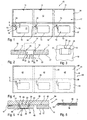
- Fig. 1 shows in a utility device 10 three interconnected trained Transponderinlays 11, each having a substrate layer 12 having arranged thereon, an antenna coil 13 and a chip module 14 comprising transponder unit 15.
- Fig. 1 beyond separating lines 16 are shown, along which a separation of the transponder inlays 11 can be made from the utility arrangement.
- Fig. 1 shows the transponder inlays 11 in a plan view with an upwardly facing contact surface 17, on the, as well as in Fig. 2 represented, a wire conductor 18 is arranged coil-shaped and embedded in the contact surface 17.
- Fig. 5 shows, free wire conductor ends 19, 20 with contact surfaces 21, 22 of a arranged in the contact surface 17 of the substrate layer 12 chip carrier 23 of the chip module 14 contacted.
- the chip module 14 is located in one of the FIGS. 2 and 3
- the window opening 30 is in the FIGS. 2 and 3 deviating from the illustration in Fig. 1 omitted inserted into the window opening 30 chip module 14.
- the window opening 30 is stepped and has a contact surface 17 facing edge shoulder 24 which serves to receive the chip carrier 23 ( Fig. 5 ) and, like Fig. 3 shows, a receiving cross-section 25 which is formed larger than a receiving cross-section 26 of a to an underside 27 of the substrate layer 12 toward extending through hole 28 which serves to receive a chip housing 29 of the chip module 14 ( Fig. 5 ).
- the chip module 14 used in the present exemplary embodiment is a chip module 14 with a chip carrier 23 which is designed to be larger than the chip housing 29 in only one dimension. Therefore, in the exemplary embodiment illustrated here, the edge shoulder 24 is designed such that the edge shoulder 24 only at two opposite edge portions support surfaces 51, 52 forms for the chip carrier 23 ( Fig. 3 ).
- a stamping tool 31 can be used which has a stamp tip 33 bounded by a stamp collar 32.
- the punch tip 33 has one of the passage opening 28 corresponding Cross section and the punch collar 32 has a cross section corresponding to the edge shoulder 24.
- the stamp tip 33 is provided at the edge of its end face 34 with a circumferentially formed cutting edge 35.
- the punch tool 31 can be moved with an intermediate arrangement of the substrate layer 12 against a support surface 53, so that substantially based on a punching process, the through hole 28 is generated by the action of the cutting edge 35 on the substrate layer 12.
- this feed movement 36 can be acted upon by ultrasonic vibrations in the direction of the feed movement or transversely thereto, so that relative heating of the substrate layer 12 takes place by the relative movement between the punch collar 32 and the contact surface 17 of the substrate layer 12.
- this heating the compression of the substrate layer 12 by the advancing movement 36 is irreversibly, ie virtually frozen.
- the material selected for the substrate layer 12 is a thermoelastic material, despite the thermal stress of the material, a certain elasticity is maintained in the compressed region of the peripheral shoulder 24. In principle, however, it is also possible to have a window opening in the in FIGS. 2 and 3 to produce shown type in a thermoplastic material.
- transponder inlays 11 of the utility device 10 are double-sided with a transponder page 37, on the each of the transponder unit 15 is located, and with a blank page 39, which is divided by a Falzaus originallyung of the transponder side 37 and coextensive with the transponder side 37 of the substrate layer 12.
- a layer structure 40 is illustrated with cover pages 49 formed integrally with one another in a utility arrangement 41.
- the utility arrangement 41 consists of the in Fig. 1 illustrated utility assembly 10 with the transponder inlays 11 and arranged on the contact surface 17 utility device 54 with composite cover layers 42nd Fig. 5 shows in a partial sectional view of the layer structure 40 of the utility assembly 41 and a cover page formed therein 49 in an enlarged view.
- the chip module 14 is arranged in the window opening 30 of the substrate layer 12 such that a contact side 43 of the chip carrier 23 is substantially flush with the contact surface 17 of the substrate layer 12.
- a housing upper side 45 is in this case set back slightly inward into the window opening 30 or arranged substantially flush with an underside 46 of the substrate layer 12.
- the chip carrier 23 is bonded to the support surfaces 51, 52 of the edge shoulder 24.
- Fig. 5 further shows that between the cover layer 42 and the contact surface 17 of the substrate layer 12 and the transponder inlays 11, an adhesive intermediate layer 47 connecting the cover layer 42 and the transponder inlay 11 to a fixed layer structure 40 is arranged.
- the contacted with the contact surfaces 21, 22 of the chip carrier 23 wire conductor ends 19, 20 of the antenna coil 13 are accommodated to a substantial extent in the intermediate layer 47, so that even with an inelastic formation of the cover layer 42 an image of the wire conductor ends 19, 20 in an outer or visible side 48 of the cover layer 42 is not to be feared.
Landscapes
- Engineering & Computer Science (AREA)
- Physics & Mathematics (AREA)
- General Physics & Mathematics (AREA)
- Theoretical Computer Science (AREA)
- Computer Hardware Design (AREA)
- Microelectronics & Electronic Packaging (AREA)
- Credit Cards Or The Like (AREA)
- Adornments (AREA)
Description
- Die vorliegende Erfindung betrifft ein Verfahren zur Herstellung eines Transponderinlays gemäß dem Oberbegriff des Anspruchs 1.
- Die aktuelle Entwicklung im Bereich personaler Dokumente geht dahin, die konventionell zum Einsatz kommenden Dokumente zur Personenidentifikation mit Transpondern zu ergänzen, die ein berührungsloses, automatisiertes Auslesen der auf einem Chip des Transponders gespeicherten Daten ermöglichen. Derartige Transponder umfassen neben dem Chip eine Antennenspule, die den berührungslosen Datenzugriff ermöglicht.
- Die Integration oder Implementierung solcher Transponder in konventionelle Personaldokumente, die aufgenommen in einem Dokumenteneinband eine Vielzahl von Papierseiten enthalten, stellt besondere Anforderungen an das Design der Transpondereinheiten bzw. der so genannten Transponderinlays, die auf einer Substratlage die Transpondereinheit aufweisen. Es liegt auf der Hand, dass es als wünschenswert angesehen wird, durch die Implementierung eines derartigen Tranpsonderinlays in ein Passdokument das bekannte Format der Passdokumente möglichst wenig zu beeinträchtigen. Darüber hinaus soll auch die Handhabung der Passdokumente, also beispielsweise das Blättern in solchen Dokumenten, möglichst wenig beeinflusst werden. Andererseits ergeben sich natürlich aus der Handhabung der Passdokumente wiederum besondere mechanische Belastungen für die Transponderinlays bzw. für die auf den Substratlagen der Transponderinlays angeordneten Transpondereinheiten.
- Aus den vorgenannten Gründen geht man daher davon aus, dass es besonders darauf ankommt, die für die Implementation in Passdokumente bestimmte Transponderinlays möglichst dünn auszuführen. Dabei sind der Reduzierung der Dicke der für die Transponderinlays verwendeten Substratlagen allein schon durch die Dicke der Chipmodule Grenzen gesetzt, wenn man davon ausgeht, dass die Chipmodule im Wesentlichen oberflächenbündig in den Transponderinlays aufgenommen werden sollen.
- Ein wesentlicher Aufwand bei der Herstellung ist daher mit der Ausbildung geeigneter Ausnehmungen oder Fensteröffnungen in den Substratlagen verbunden.
- Aus der
US 2007/0141760 A1 ist ein Verfahren ersichtlich, bei dem die Öffnung zur Aufnahme eines Chipmoduls entweder durch Einpressen des Chipmoduls in das Kunststoffsubstrat oder durch vorherige Ausbildung einer geeigneten Öffnung durch Verwendung einer mit Druck und Temperatur auf das Substrat wirkenden Vorrichtung erzeugt wird. - Die
US 4.625.102 zeigt ein Verfahren zur Anordnung eines Chipmoduls in einem Kunststoffsubstrat, bei dem das Chipmodul in das Kunststoffsubstrat eingedrückt wird. Dabei kommt im Ergebnis eine mit einem Randabsatz versehene Fensteröffnung zustande, dadurch, dass bereits zuvor, also vor dem Einpressen des Chipmoduls in das Kunststoffsubstrat, eine als Fensteröffnung ausgebildete Durchgangsöffnung in das Kunststoffsubstrat eingebracht wurde. - Die
WO 88/08171 - Die
DE 4241482 A1 zeigt ein Verfahren zur Herstellung einer Transponderkarte, bei dem ein Stempelwerkzeug zur Formung einer mit einem Randabsatz versehenen Fensteröffnung verwendet wird. Bereits vor Einsatz des Stempelwerkzeugs wird ein Sackloch vermittels eines Fräsers in das Kunststoffmaterial eingebracht. Dieses Sackloch ist so dimensioniert, dass es die Aufnahme eines bei Herstellung des Randabsatzes durch Einwirkung des Stempelwerkzeugs verdrängten Materials ermöglicht. - Der vorliegenden Erfindung liegt daher die Aufgabe zugrunde, ein Verfahren zur Herstellung eines Transponderinlays vorzuschlagen, dass die Herstellung möglichst dünn ausgebildeter Transponderinlays mit einem vergleichsweise geringen Aufwand ermöglicht.
- Diese Aufgabe wird durch ein Verfahren mit den Merkmalen des Anspruchs 1 gelöst.
- Erfindungsgemäß wird zur Ausbildung einer das Chipmodul aufnehmenden Fensteröffnung eine Durchgangsöffnung in der Substratlage hergestellt, und der Umfangsrand der Durchgangsöffnung wird zur Erzielung eines komprimierten Randabsatzes mit reduzierter Dicke mit Druck und Temperatur beaufschlagt.
- Weiterhin erfolgt erfindungsgemäß die Beaufschlagung mit Druck und Temperatur vermittels eines ultraschallerregten Stempelwerkzeugs erfolgt. Die Temperaturbeaufschlagung kann dabei durch eine externe Beheizung des Stempelwerkzeugs erfolgen, oder auch durch eine durch die mechanische Reibung in Folge der Ultraschallschwingungen des Stempelwerkzeugs induzierte Erwärmung des Stempelwerkzeugs bzw. der Substratlage, also ohne externe Überheizung.
- Weiterhin wird erfindungsgemäß das Stempelwerkzeug gleichzeitig zur Ausbildung der Durchgangsöffnung verwendet, da somit sowohl die Ausbildung der Fensteröffnung als auch die Ausbildung des Randabsatzes in einem Bearbeitungsvorgang mit ein und demselben Werkzeug erfolgen kann.
- Eine hinsichtlich des universellen Werkzeugeinsatzes optimierte Variante des Verfahrens wird möglich, wenn das Stempelwerkzeug gleichzeitig zur Einbettung eines zur Herstellung der Antennenspule verwendeten Drahtleiters in die Kontaktoberfläche der Substratlage dient.
- Eine bevorzugte Ausführungsform des Transponderinlays wird zusammen mit einer Erläuterung der mit der Herstellung des Transponderinlays verbundenen Verfahrensschritte anhand der Zeichnung verdeutlicht.
- Es zeigen:
-
Fig. 1 eine Nutzenanordnung mit drei zusammenhängend ausgebildeten Transponderinlays; -
Fig. 2 eine Fensteröffnung einer Substratlage in vergrößerter Darstellung gemäß Schnittlinienverlauf II-II inFig. 1 ; -
Fig. 3 die inFig. 2 dargestellte Fensteröffnung in Draufsicht; -
Fig. 4 eine Nutzenanordnung mit drei zusammenhängend ausgebildeten Einbandseiten zur Herstellung eines Lagenaufbaus für ein Passdokument; -
Fig. 5 eine Teilschnittdarstellung des inFig. 4 dargestellten Lagenaufbaus gemäß Schnittlinienverlauf V-V inFig. 4 ; -
Fig. 6 eine umgefalzte Einbandseite zur Ausbildung eines Einbandrückens. -
Fig. 1 zeigt in einer Nutzenanordnung 10 drei miteinander zusammenhängend ausgebildete Transponderinlays 11, die jeweils eine Substratlage 12 mit einer darauf angeordneten, eine Antennenspule 13 und ein Chipmodul 14 umfassenden Transpondereinheit 15 aufweisen. InFig. 1 sind darüber hinaus Trennlinien 16 eingezeichnet, längs derer eine Vereinzelung der Transponderinlays 11 aus der Nutzenanordnung erfolgen kann. - Die Darstellung gemäß
Fig. 1 zeigt die Transponderinlays 11 in einer Draufsicht mit einer nach oben gewandten Kontaktoberfläche 17, auf der, wie auch inFig. 2 dargestellt, ein Drahtleiter 18 spulenförmig angeordnet und in die Kontaktoberfläche 17 eingebettet ist. Wie insbesondereFig. 5 zeigt, sind freie Drahtleiterenden 19, 20 mit Kontaktflächen 21, 22 eines in der Kontaktoberfläche 17 der Substratlage 12 angeordneten Chipträgers 23 des Chipmoduls 14 kontaktiert. - Das Chipmodul 14 befindet sich in einer in den
Fig. 2 und 3 dargestellten Fensteröffnung 30. Aus Gründen der übersichtlichen Darstellung der Fensteröffnung 30 ist in denFig. 2 und 3 abweichend von der Darstellung inFig. 1 das in die Fensteröffnung 30 eingesetzte Chipmodul 14 weggelassen. Die Fensteröffnung 30 ist abgestuft ausgebildet und weist einen der Kontaktoberfläche 17 zugewandten Randabsatz 24 auf, der zur Aufnahme des Chipträgers 23 dient (Fig. 5 ) und, wieFig. 3 zeigt, einen Aufnahmequerschnitt 25 aufweist, der größer ausgebildet ist als ein Aufnahmequerschnitt 26 einer sich zu einer Unterseite 27 der Substratlage 12 hin erstreckenden Durchgangsöffnung 28, die zur Aufnahme eines Chipgehäuses 29 des Chipmoduls 14 dient (Fig. 5 ). - Sowohl die Durchgangsöffnung 28 als auch der Randabsatz 24 sind dem jeweilig aufzunehmenden Chipmodul angepasst. Bei dem im vorliegenden Ausführungsbeispiel verwendeten Chipmodul 14 handelt es sich um ein Chipmodul 14 mit einem Chipträger 23, der lediglich in einer Dimension größer ausgebildet ist als das Chipgehäuse 29. Daher ist in dem hier dargestellten Ausführungsbeispiel der Randabsatz 24 so ausgebildet, dass der Randabsatz 24 lediglich an zwei einander gegenüberliegenden Randabschnitten Stützflächen 51, 52 für den Chipträger 23 bildet (
Fig. 3 ). - Zur Herstellung der in den
Fig. 2 und 3 dargestellten Fensteröffnung 30 kann beispielsweise ein Stempelwerkzeug 31 zum Einsatz kommen, das eine durch einen Stempelbund 32 begrenzte Stempelspitze 33 aufweist. Die Stempelspitze 33 weist einen der Durchgangsöffnung 28 entsprechenden Querschnitt und der Stempelbund 32 einen dem Randabsatz 24 entsprechenden Querschnitt auf. Darüber hinaus ist die Stempelspitze 33 am Rand ihrer Stirnfläche 34 mit einer umlaufend ausgebildeten Schneidkante 35 versehen. - Zur Herstellung der in den
Fig. 2 und 3 dargestellten Fensteröffnung 30 kann das Stempelwerkzeug 31 unter zwischenliegender Anordnung der Substratlage 12 gegen eine Auflagefläche 53 verfahren werden, so dass im Wesentlichen basierend auf einem Stanzvorgang die Durchgangsöffnung 28 durch die Einwirkung der Schneidkante 35 auf die Substratlage 12 erzeugt wird. Gleichzeitig mit einer Vorschubbewegung 36 des Stempelwerkzeugs 31 kann diese Vorschubbewegung 36 mit Ultraschallschwingungen in Richtung der Vorschubbewegung oder auch quer dazu beaufschlagt werden, so dass durch die Relativbewegung zwischen dem Stempelbund 32 und der Kontaktoberfläche 17 der Substratlage 12 eine relative Erwärmung der Substratlage 12 erfolgt. In Folge dieser Erwärmung wird die durch die Vorschubbewegung 36 erfolgte Komprimierung der Substratlage 12 irreversibel, also quasi eingefroren. Wenn es sich bei dem für die Substratlage 12 ausgewählten Material um ein thermoelastisches Material handelt, bleibt trotz der thermischen Belastung des Materials eine gewisse Elastizität im komprimierten Bereich des Randabsatzes 24 erhalten. Grundsätzlich ist es jedoch auch möglich, eine Fensteröffnung in der in denFig. 2 und 3 dargestellten Art in einem thermoplastischen Material herzustellen. - Die in
Fig. 1 dargestellten Transponderinlays 11 der Nutzenanordnung 10 sind doppelseitig ausgebildet mit einer Transponderseite 37, auf der sich jeweils die Transpondereinheit 15 befindet, und mit einer Leerseite 39, die durch eine Falzausnehmung von der Transponderseite 37abgeteilt und flächengleich mit der Transponderseite 37 der Substratlage 12 ist. - In den
Fig. 4 und 5 ist ein Lagenaufbau 40 mit in einer Nutzenanordnung 41 zusammenhängend miteinander ausgebildeten Einbandseiten 49 dargestellt. Die Nutzenanordnung 41 besteht aus der inFig. 1 dargestellten Nutzenanordnung 10 mit den Transponderinlays 11 und einer auf der Kontaktoberfläche 17 angeordneten Nutzenanordnung 54 mit im Verbund angeordneten Decklagen 42.Fig. 5 zeigt in einer Teilschnittdarstellung den Lagenaufbau 40 der Nutzenanordnung 41 bzw. einer darin ausgebildeten Einbandseite 49 in vergrößerter Darstellung. Insbesondere ist zu erkennen, dass das Chipmodul 14 so in der Fensteröffnung 30 der Substratlage 12 angeordnet ist, dass eine Kontaktseite 43 des Chipträgers 23 im Wesentlichen flächenbündig mit der Kontaktoberfläche 17 der Substratlage 12 ist. Das sich nach unten vom Chipträger 23 erstreckende, eine hier nicht näher dargestellte Chipeinheit einhüllende Chipgehäuse 29 ist vollständig in der Durchgangsöffnung 28 der Fensteröffnung 30 aufgenommen. Eine Gehäuseoberseite 45 befindet sich dabei leicht nach innen in die Fensteröffnung 30 zurückversetzt oder im Wesentlichen bündig mit einer Unterseite 46 der Substratlage 12 angeordnet. Bei dem inFig. 5 dargestellten Ausführungsbeispiel ist der Chipträger 23 mit den Stützflächen 51, 52 des Randabsatzes 24 verklebt. -
Fig. 5 zeigt ferner, dass zwischen der Decklage 42 und der Kontaktoberfläche 17 der Substratlage 12 bzw. des Transponderinlays 11 eine die Decklage 42 und das Transponderinlay 11 zu einem fixierten Lagenaufbau 40 verbindende adhäsive Zwischenschicht 47 angeordnet ist. Die mit den Kontaktflächen 21, 22 des Chipträgers 23 kontaktierten Drahtleiterenden 19, 20 der Antennenspule 13 befinden sich zu einem wesentlichen Teil in der Zwischenschicht 47 aufgenommen, so dass auch bei einer unelastischen Ausbildung der Decklage 42 eine Abbildung der Drahtleiterenden 19, 20 in einer Außen- oder Sichtseite 48 der Decklage 42 nicht zu befürchten steht. - Durch den in
Fig. 5 dargestellten Lagenaufbau 40 werden die in der Nutzenanordnung 54 gemäßFig. 4 in einem zusammenhängenden Verbund angeordneten Einbandseiten 49 gebildet, die durch einen Ausstanzvorgang längs der Trennlinien 16 vereinzelt werden können. Da sich die Decklagen 42 kontinuierlich über die Falzausnehmung 38 in der Substratlage 12 bzw. dem Transponderinlay 11 hinweg erstrecken, weisen die Einbandseiten 49 im Bereich der Falzausnehmungen 38 eine entsprechende Querschnittsreduzierung auf, die ein Umschlagen oder eine Falzung der Einbandseiten 49 um den durch die Falzausnehmung 38 definierten Einbandrücken 50, wie inFig. 6 dargestellt, ermöglicht. In einem durch die Leerseite 39 und die Transponderseite 37 des Transponderinlays 11 begrenzten Einlegeraum können nun beliebige Zwischenseiten eingefügt werden, die in konventioneller Art und Weise Personendaten enthalten.
Claims (2)
- Verfahren zur Herstellung eines Transponderinlays (11) für einen Lagenaufbau (40) eines Personaldokuments, wobei eine Substratlage (12) mit einer Antennenspule und einem Chipmodul sowie einer Fensteröffnung versehen wird und die Substrattage (12) eine Kontaktoberfläche (17 aufweist, auf der ein Chipträger des Chipmoduls mit der Antennenspule kontaktiert ist, ,
dadurch gekennzeichnet,
dass zur Ausbildung einer die Aufnahme des Chipmoduls ermöglichenden Fensteröffnung (30), die einen komprimierten Randabsatz (24) aufweist, eine Durchgangsöffnung (28) in der Substratlage (12) hergestellt und der Umfangsrand der Durchgangsöffnung zur Erzielung einer im Bereich des Umfangsrands reduzierten Dicke der Substratlage mit Druck und Temperatur beaufschlagt wird, wobei die Beaufschlagung mit Druck und Temperatur vermittels eines ultraschallerregten Stempelwerkzeugs (31) erfolgt, und das Stempelwerkzeug (31) gleichzeitig zur Ausbildung der Durchgangsöffnung (28) dient. - Verfahren nach Anspruch 1,
dadurch gekennzeichnet, dass das Stempelwerkzeug (31) gleichzeitig zur Einbettung eines zur Herstellung der Antennenspule (13) verwendeten Drahtleiters (18) in die Kontaktoberfläche (17) der Substratlage (12) dient.
Priority Applications (1)
| Application Number | Priority Date | Filing Date | Title |
|---|---|---|---|
| PL08785744T PL2074560T3 (pl) | 2007-10-05 | 2008-08-28 | Sposób wytwarzania mozaiki transpondera do dokumentów osobistych |
Applications Claiming Priority (2)
| Application Number | Priority Date | Filing Date | Title |
|---|---|---|---|
| US11/867,804 US20090091424A1 (en) | 2007-10-05 | 2007-10-05 | Transponder inlay for a personal document and method of manufacturing same |
| PCT/EP2008/007049 WO2009046791A1 (de) | 2007-10-05 | 2008-08-28 | Transponderinlay für ein personaldokument und verfahren zu dessen herstellung |
Publications (2)
| Publication Number | Publication Date |
|---|---|
| EP2074560A1 EP2074560A1 (de) | 2009-07-01 |
| EP2074560B1 true EP2074560B1 (de) | 2011-10-05 |
Family
ID=40043959
Family Applications (1)
| Application Number | Title | Priority Date | Filing Date |
|---|---|---|---|
| EP08785744A Not-in-force EP2074560B1 (de) | 2007-10-05 | 2008-08-28 | Verfahren zur herstellung eines transponderinlays für ein personaldokument |
Country Status (11)
| Country | Link |
|---|---|
| US (2) | US20090091424A1 (de) |
| EP (1) | EP2074560B1 (de) |
| KR (1) | KR101035048B1 (de) |
| AT (1) | ATE527627T1 (de) |
| AU (1) | AU2008310104B2 (de) |
| CA (1) | CA2669079C (de) |
| EG (1) | EG26352A (de) |
| ES (1) | ES2371694T3 (de) |
| MX (1) | MX2009005695A (de) |
| PL (1) | PL2074560T3 (de) |
| WO (1) | WO2009046791A1 (de) |
Cited By (1)
| Publication number | Priority date | Publication date | Assignee | Title |
|---|---|---|---|---|
| DE102018112476A1 (de) | 2017-06-02 | 2018-12-06 | Ulrich Lang | Verfahren und Fertigungsanlage zum Herstellen eines Foliensubstrats |
Families Citing this family (24)
| Publication number | Priority date | Publication date | Assignee | Title |
|---|---|---|---|---|
| US8608080B2 (en) * | 2006-09-26 | 2013-12-17 | Feinics Amatech Teoranta | Inlays for security documents |
| WO2010132117A1 (en) * | 2009-05-13 | 2010-11-18 | American Bank Note Company | Cover and method of manufacturing the same |
| DE102009038802A1 (de) | 2009-08-25 | 2011-03-10 | Mühlbauer Ag | Wert- und Sicherheitsdokument in der Form eines Buches, Verfahren zur Herstellung eines derartigen Wert- und Sicherheitsdokumentes |
| DE102010011504A1 (de) | 2010-03-16 | 2012-06-14 | Mühlbauer Ag | Verfahren zur Herstellung einer Transponderantenne, Transponderinlay mit einer derartigen Transponderantenne |
| FR2959581B1 (fr) | 2010-04-28 | 2012-08-17 | Arjowiggins Security | Insert fibreux constitue en une seule couche et equipe d'un dispositif electronique a communication sans contact. |
| US8991712B2 (en) | 2010-08-12 | 2015-03-31 | Féinics Amatech Teoranta | Coupling in and to RFID smart cards |
| US9033250B2 (en) | 2010-08-12 | 2015-05-19 | Féinics Amatech Teoranta | Dual interface smart cards, and methods of manufacturing |
| US8789762B2 (en) | 2010-08-12 | 2014-07-29 | Feinics Amatech Teoranta | RFID antenna modules and methods of making |
| US9195932B2 (en) | 2010-08-12 | 2015-11-24 | Féinics Amatech Teoranta | Booster antenna configurations and methods |
| US9112272B2 (en) | 2010-08-12 | 2015-08-18 | Feinics Amatech Teoranta | Antenna modules for dual interface smart cards, booster antenna configurations, and methods |
| EP2718876A1 (de) | 2011-06-04 | 2014-04-16 | Féinics AmaTech Teoranta | Herstellung eines substrats zum einbetten eines drahtes |
| US8763914B2 (en) | 2012-01-17 | 2014-07-01 | On Track Innovations Ltd. | Decoupled contactless bi-directional systems and methods |
| DE102012010560B4 (de) | 2012-05-29 | 2020-07-09 | Mühlbauer Gmbh & Co. Kg | Transponder, Verfahren zur Herstellung eines Transponders und Vorrichtungzum Herstellen des Transponders |
| FR2995709A1 (fr) | 2012-09-18 | 2014-03-21 | Arjowiggins Security | Procede de fabrication d'une structure a puce electronique et structure ainsi fabriquee. |
| WO2019224575A1 (en) | 2018-05-22 | 2019-11-28 | Tyco Fire & Security Gmbh | Elongate flexible tag |
| WO2019224364A1 (de) | 2018-05-24 | 2019-11-28 | Ulrich Lang | Verfahren und fertigungsanlage zum herstellen eines foliensubstrats |
| US12223814B2 (en) | 2019-09-16 | 2025-02-11 | Sensormatic Electronics, LLC | Security tag for textiles using conductive thread |
| US11443160B2 (en) | 2019-09-18 | 2022-09-13 | Sensormatic Electronics, LLC | Systems and methods for laser tuning and attaching RFID tags to products |
| US10970613B1 (en) | 2019-09-18 | 2021-04-06 | Sensormatic Electronics, LLC | Systems and methods for providing tags adapted to be incorporated with or in items |
| US11055588B2 (en) | 2019-11-27 | 2021-07-06 | Sensormatic Electronics, LLC | Flexible water-resistant sensor tag |
| US12524640B2 (en) | 2019-11-27 | 2026-01-13 | Sensormatic Electronics, LLC | Flexible water-resistant sensor tag |
| US11755874B2 (en) | 2021-03-03 | 2023-09-12 | Sensormatic Electronics, LLC | Methods and systems for heat applied sensor tag |
| US11869324B2 (en) | 2021-12-23 | 2024-01-09 | Sensormatic Electronics, LLC | Securing a security tag into an article |
| US12536401B2 (en) | 2022-08-31 | 2026-01-27 | Sensormatic Electronics, LLC | Security tag |
Citations (2)
| Publication number | Priority date | Publication date | Assignee | Title |
|---|---|---|---|---|
| WO1988008171A1 (fr) * | 1987-04-14 | 1988-10-20 | Lgz Landis & Gyr Zug Ag | Support pour piece d'identite et procede de fabrication de ce support |
| DE4241482A1 (de) * | 1992-12-09 | 1994-06-16 | Siemens Ag | Verfahren und Einrichtung zur Herstellung von IC-Karten |
Family Cites Families (11)
| Publication number | Priority date | Publication date | Assignee | Title |
|---|---|---|---|---|
| US4483067A (en) * | 1981-09-11 | 1984-11-20 | U.S. Philips Corporation | Method of manufacturing an identification card and an identification manufactured, for example, by this method |
| EP0128822B1 (de) * | 1983-06-09 | 1987-09-09 | Flonic S.A. | Verfahren zur Herstellung von Speicherkarten und hierdurch hergestellte Karten |
| FR2579799B1 (fr) * | 1985-03-28 | 1990-06-22 | Flonic Sa | Procede de fabrication de cartes a memoire electronique et cartes obtenues suivant ledit procede |
| DE4410732C2 (de) * | 1994-03-28 | 1997-05-07 | Amatech Gmbh & Co Kg | Verfahren zur Anordnung einer zumindest einen Chip und eine Drahtspule aufweisenden Transpondereinheit auf einem Substrat sowie Chipkarte mit entsprechend angeordneter Transpondereinheit |
| US6492717B1 (en) * | 1999-08-03 | 2002-12-10 | Motorola, Inc. | Smart card module and method of assembling the same |
| DE10328776B3 (de) * | 2003-06-25 | 2005-01-27 | Groz-Beckert Kg | Stanzvorrichtung für flächige Gegenstände |
| DE102004004469A1 (de) * | 2003-12-22 | 2005-08-18 | Smartrac Technology Ltd. | Verfahren zur Herstellung eines Sicherheitslagenaufbaus sowie Sicherheitslagenaufbau und einen solchen enthaltende Identifikationsdokumente |
| US7612677B2 (en) * | 2005-01-28 | 2009-11-03 | Smartrac Ip B.V. | Method for producing a security layered construction and security layered construction and identification documents containing such a construction |
| FR2881252A1 (fr) * | 2005-01-24 | 2006-07-28 | Ask Sa | Dispositif d'idenfication radiofrequence resistant aux milieux et son procede de fabrication |
| US8067253B2 (en) * | 2005-12-21 | 2011-11-29 | Avery Dennison Corporation | Electrical device and method of manufacturing electrical devices using film embossing techniques to embed integrated circuits into film |
| US20080186186A1 (en) * | 2007-02-06 | 2008-08-07 | Opsec Security Group, Inc. | Apparatus and method for selectively permitting and resisting reading of radio frequency chips |
-
2007
- 2007-10-05 US US11/867,804 patent/US20090091424A1/en not_active Abandoned
- 2007-11-21 KR KR1020070119104A patent/KR101035048B1/ko not_active Expired - Fee Related
-
2008
- 2008-08-28 AT AT08785744T patent/ATE527627T1/de active
- 2008-08-28 PL PL08785744T patent/PL2074560T3/pl unknown
- 2008-08-28 EP EP08785744A patent/EP2074560B1/de not_active Not-in-force
- 2008-08-28 ES ES08785744T patent/ES2371694T3/es active Active
- 2008-08-28 WO PCT/EP2008/007049 patent/WO2009046791A1/de not_active Ceased
- 2008-08-28 AU AU2008310104A patent/AU2008310104B2/en not_active Ceased
- 2008-08-28 CA CA2669079A patent/CA2669079C/en active Active
- 2008-08-28 MX MX2009005695A patent/MX2009005695A/es active IP Right Grant
-
2009
- 2009-06-22 EG EG2009060958A patent/EG26352A/en active
-
2011
- 2011-03-09 US US13/043,718 patent/US8188867B2/en active Active
Patent Citations (2)
| Publication number | Priority date | Publication date | Assignee | Title |
|---|---|---|---|---|
| WO1988008171A1 (fr) * | 1987-04-14 | 1988-10-20 | Lgz Landis & Gyr Zug Ag | Support pour piece d'identite et procede de fabrication de ce support |
| DE4241482A1 (de) * | 1992-12-09 | 1994-06-16 | Siemens Ag | Verfahren und Einrichtung zur Herstellung von IC-Karten |
Cited By (2)
| Publication number | Priority date | Publication date | Assignee | Title |
|---|---|---|---|---|
| DE102018112476A1 (de) | 2017-06-02 | 2018-12-06 | Ulrich Lang | Verfahren und Fertigungsanlage zum Herstellen eines Foliensubstrats |
| DE102018112476B4 (de) | 2017-06-02 | 2022-01-27 | Ulrich Lang | Verfahren und Fertigungsanlage zum Herstellen eines Foliensubstrats |
Also Published As
| Publication number | Publication date |
|---|---|
| KR20090035406A (ko) | 2009-04-09 |
| PL2074560T3 (pl) | 2012-03-30 |
| ES2371694T3 (es) | 2012-01-09 |
| ATE527627T1 (de) | 2011-10-15 |
| EG26352A (en) | 2013-08-26 |
| US20110155811A1 (en) | 2011-06-30 |
| US8188867B2 (en) | 2012-05-29 |
| WO2009046791A1 (de) | 2009-04-16 |
| CA2669079C (en) | 2012-05-01 |
| CA2669079A1 (en) | 2009-04-16 |
| AU2008310104B2 (en) | 2012-09-20 |
| EP2074560A1 (de) | 2009-07-01 |
| US20090091424A1 (en) | 2009-04-09 |
| MX2009005695A (es) | 2009-06-08 |
| KR101035048B1 (ko) | 2011-05-19 |
| AU2008310104A1 (en) | 2009-04-16 |
Similar Documents
| Publication | Publication Date | Title |
|---|---|---|
| EP2074560B1 (de) | Verfahren zur herstellung eines transponderinlays für ein personaldokument | |
| DE10338444B4 (de) | Transponderinlay für ein Dokument zur Personenidentifikation sowie Verfahren zu dessen Herstellung | |
| DE102008019571A1 (de) | Chipkarte und Verfahren zu deren Herstellung | |
| EP1861262B2 (de) | Datenseite zur einbindung in ein passbuch | |
| EP1814723B1 (de) | Einlageblatt, insbesondere für ein buchartiges identifikationsdokument, verfahren und vorrichtung zur herstellung eines einlageblattes | |
| EP2303596B1 (de) | Verfahren zum herstellen einer dokumentenkarte, die in ein als buch ausgeführtes sicherheitsdokument einfügbar ist, und dokumentenkarte | |
| EP1603757B1 (de) | Verfahren zur herstellung einer buchdeckeneinlage und eines buchartigen wertdokumentes sowie eine buchdeckeneinlage und ein buchartiges wertdokument | |
| DE19741984B4 (de) | Chipträger zur Herstellung einer Chipkarte sowie Verfahren zur Herstellung einer derartigen Chipkarte | |
| EP1709575B1 (de) | Sicherheitslagenaufbau und einen solchen enthaltende identifikationsdokumente | |
| EP0212506A2 (de) | Verfahren zum Herstellen einer Ausweiskarte und Ausweiskarte | |
| EP2079107B1 (de) | Verfahren zum Herstellen eines kartenförmigen Datenträgers und nach diesem Verfahren hergestellter Datenträger | |
| EP3297844B1 (de) | Verfahren zur herstellung eines buchblocks, insbesondere für ein buchartiges dokument sowie ein einlageblatt und ein buchblock | |
| DE102012203276B4 (de) | Verfahren zum Herstellen einer mindestens ein elektronisches Bauelement aufweisenden Foliengruppe und Verfahren zur Herstellung eines Wert- und/oder Sicherheitsdokuments | |
| DE102016014995A1 (de) | Umschlag für ein buchartiges Wert- oder Sicherheitsdokument | |
| DE102018009837A1 (de) | Datenseite, insbesondere für ein buchartiges Dokument sowie Verfahren zu dessen Herstellung | |
| EP1517266B1 (de) | Verfahren und Vorrichtung zum Einbringen einer elektronischen Schaltkreisanordnung in ein buchförmiges Dokument sowie hiernach hergestelltes buchförmiges Dokument | |
| EP1798671B1 (de) | Verfahren zum Herstellen eines kartenförmigen Datenträgers | |
| WO2007062696A1 (de) | Verfahren zur herstellung einer gefalteten trägeranordnung, insbesondere für ein identifikationsdokument sowie eine trägeranordnung | |
| EP3339046B1 (de) | Datenträger sowie verfahren und vorrichtung zur herstellung eines solchen datenträgers für ein buchartiges dokument | |
| EP2679399B1 (de) | Identifikationsdokument mit Fälschungsschutz | |
| EP4621641A1 (de) | Herstellen eines trägerkörpers für einen portablen datenträger | |
| EP4620694A1 (de) | Rohling und verfahren zum herstellen eines vorkaschierten rohlings, broschüre und ver- fahren zum herstellen einer buchförmigen broschüre sowie einband für eine broschüre | |
| DE102022122187A1 (de) | Chip-Anordnung, Verfahren zum Bilden einer Chip-Anordnung und Verfahren zum Nutzen einer Chip-Anordnung | |
| DE202008007219U1 (de) | Druckereiprodukt | |
| DE102008049669A1 (de) | Transponderinlay für ein Dokument zur Personenidentifikation und ein Verfahren zur Herstellung eines Transponderinlays |
Legal Events
| Date | Code | Title | Description |
|---|---|---|---|
| PUAI | Public reference made under article 153(3) epc to a published international application that has entered the european phase |
Free format text: ORIGINAL CODE: 0009012 |
|
| 17P | Request for examination filed |
Effective date: 20090515 |
|
| AK | Designated contracting states |
Kind code of ref document: A1 Designated state(s): AT BE BG CH CY CZ DE DK EE ES FI FR GB GR HR HU IE IS IT LI LT LU LV MC MT NL NO PL PT RO SE SI SK TR |
|
| 17Q | First examination report despatched |
Effective date: 20090824 |
|
| GRAP | Despatch of communication of intention to grant a patent |
Free format text: ORIGINAL CODE: EPIDOSNIGR1 |
|
| RTI1 | Title (correction) |
Free format text: METHOD FOR THE PRODUCTION OF A TRANSPONDER INLAY FOR A PERSONAL DOCUMENT |
|
| DAX | Request for extension of the european patent (deleted) | ||
| GRAS | Grant fee paid |
Free format text: ORIGINAL CODE: EPIDOSNIGR3 |
|
| GRAA | (expected) grant |
Free format text: ORIGINAL CODE: 0009210 |
|
| AK | Designated contracting states |
Kind code of ref document: B1 Designated state(s): AT BE BG CH CY CZ DE DK EE ES FI FR GB GR HR HU IE IS IT LI LT LU LV MC MT NL NO PL PT RO SE SI SK TR |
|
| REG | Reference to a national code |
Ref country code: GB Ref legal event code: FG4D Free format text: NOT ENGLISH |
|
| REG | Reference to a national code |
Ref country code: CH Ref legal event code: EP |
|
| REG | Reference to a national code |
Ref country code: IE Ref legal event code: FG4D |
|
| REG | Reference to a national code |
Ref country code: DE Ref legal event code: R096 Ref document number: 502008005098 Country of ref document: DE Effective date: 20111208 |
|
| REG | Reference to a national code |
Ref country code: ES Ref legal event code: FG2A Ref document number: 2371694 Country of ref document: ES Kind code of ref document: T3 Effective date: 20120109 |
|
| REG | Reference to a national code |
Ref country code: NL Ref legal event code: VDEP Effective date: 20111005 |
|
| PG25 | Lapsed in a contracting state [announced via postgrant information from national office to epo] |
Ref country code: SI Free format text: LAPSE BECAUSE OF FAILURE TO SUBMIT A TRANSLATION OF THE DESCRIPTION OR TO PAY THE FEE WITHIN THE PRESCRIBED TIME-LIMIT Effective date: 20111005 |
|
| LTIE | Lt: invalidation of european patent or patent extension |
Effective date: 20111005 |
|
| REG | Reference to a national code |
Ref country code: PL Ref legal event code: T3 |
|
| PG25 | Lapsed in a contracting state [announced via postgrant information from national office to epo] |
Ref country code: LT Free format text: LAPSE BECAUSE OF FAILURE TO SUBMIT A TRANSLATION OF THE DESCRIPTION OR TO PAY THE FEE WITHIN THE PRESCRIBED TIME-LIMIT Effective date: 20111005 Ref country code: IS Free format text: LAPSE BECAUSE OF FAILURE TO SUBMIT A TRANSLATION OF THE DESCRIPTION OR TO PAY THE FEE WITHIN THE PRESCRIBED TIME-LIMIT Effective date: 20120205 Ref country code: NO Free format text: LAPSE BECAUSE OF FAILURE TO SUBMIT A TRANSLATION OF THE DESCRIPTION OR TO PAY THE FEE WITHIN THE PRESCRIBED TIME-LIMIT Effective date: 20120105 |
|
| REG | Reference to a national code |
Ref country code: HU Ref legal event code: AG4A Ref document number: E012488 Country of ref document: HU |
|
| REG | Reference to a national code |
Ref country code: IE Ref legal event code: FD4D |
|
| PG25 | Lapsed in a contracting state [announced via postgrant information from national office to epo] |
Ref country code: NL Free format text: LAPSE BECAUSE OF FAILURE TO SUBMIT A TRANSLATION OF THE DESCRIPTION OR TO PAY THE FEE WITHIN THE PRESCRIBED TIME-LIMIT Effective date: 20111005 Ref country code: GR Free format text: LAPSE BECAUSE OF FAILURE TO SUBMIT A TRANSLATION OF THE DESCRIPTION OR TO PAY THE FEE WITHIN THE PRESCRIBED TIME-LIMIT Effective date: 20120106 Ref country code: SE Free format text: LAPSE BECAUSE OF FAILURE TO SUBMIT A TRANSLATION OF THE DESCRIPTION OR TO PAY THE FEE WITHIN THE PRESCRIBED TIME-LIMIT Effective date: 20111005 Ref country code: PT Free format text: LAPSE BECAUSE OF FAILURE TO SUBMIT A TRANSLATION OF THE DESCRIPTION OR TO PAY THE FEE WITHIN THE PRESCRIBED TIME-LIMIT Effective date: 20120206 Ref country code: LV Free format text: LAPSE BECAUSE OF FAILURE TO SUBMIT A TRANSLATION OF THE DESCRIPTION OR TO PAY THE FEE WITHIN THE PRESCRIBED TIME-LIMIT Effective date: 20111005 Ref country code: HR Free format text: LAPSE BECAUSE OF FAILURE TO SUBMIT A TRANSLATION OF THE DESCRIPTION OR TO PAY THE FEE WITHIN THE PRESCRIBED TIME-LIMIT Effective date: 20111005 |
|
| PG25 | Lapsed in a contracting state [announced via postgrant information from national office to epo] |
Ref country code: CY Free format text: LAPSE BECAUSE OF FAILURE TO SUBMIT A TRANSLATION OF THE DESCRIPTION OR TO PAY THE FEE WITHIN THE PRESCRIBED TIME-LIMIT Effective date: 20111005 |
|
| PG25 | Lapsed in a contracting state [announced via postgrant information from national office to epo] |
Ref country code: EE Free format text: LAPSE BECAUSE OF FAILURE TO SUBMIT A TRANSLATION OF THE DESCRIPTION OR TO PAY THE FEE WITHIN THE PRESCRIBED TIME-LIMIT Effective date: 20111005 Ref country code: SK Free format text: LAPSE BECAUSE OF FAILURE TO SUBMIT A TRANSLATION OF THE DESCRIPTION OR TO PAY THE FEE WITHIN THE PRESCRIBED TIME-LIMIT Effective date: 20111005 Ref country code: CZ Free format text: LAPSE BECAUSE OF FAILURE TO SUBMIT A TRANSLATION OF THE DESCRIPTION OR TO PAY THE FEE WITHIN THE PRESCRIBED TIME-LIMIT Effective date: 20111005 Ref country code: IE Free format text: LAPSE BECAUSE OF FAILURE TO SUBMIT A TRANSLATION OF THE DESCRIPTION OR TO PAY THE FEE WITHIN THE PRESCRIBED TIME-LIMIT Effective date: 20111005 Ref country code: DK Free format text: LAPSE BECAUSE OF FAILURE TO SUBMIT A TRANSLATION OF THE DESCRIPTION OR TO PAY THE FEE WITHIN THE PRESCRIBED TIME-LIMIT Effective date: 20111005 Ref country code: BG Free format text: LAPSE BECAUSE OF FAILURE TO SUBMIT A TRANSLATION OF THE DESCRIPTION OR TO PAY THE FEE WITHIN THE PRESCRIBED TIME-LIMIT Effective date: 20120105 |
|
| PLBE | No opposition filed within time limit |
Free format text: ORIGINAL CODE: 0009261 |
|
| STAA | Information on the status of an ep patent application or granted ep patent |
Free format text: STATUS: NO OPPOSITION FILED WITHIN TIME LIMIT |
|
| PG25 | Lapsed in a contracting state [announced via postgrant information from national office to epo] |
Ref country code: RO Free format text: LAPSE BECAUSE OF FAILURE TO SUBMIT A TRANSLATION OF THE DESCRIPTION OR TO PAY THE FEE WITHIN THE PRESCRIBED TIME-LIMIT Effective date: 20111005 |
|
| 26N | No opposition filed |
Effective date: 20120706 |
|
| REG | Reference to a national code |
Ref country code: DE Ref legal event code: R097 Ref document number: 502008005098 Country of ref document: DE Effective date: 20120706 |
|
| BERE | Be: lapsed |
Owner name: SMARTRAC IP B.V. Effective date: 20120831 |
|
| REG | Reference to a national code |
Ref country code: CH Ref legal event code: PL |
|
| PG25 | Lapsed in a contracting state [announced via postgrant information from national office to epo] |
Ref country code: MC Free format text: LAPSE BECAUSE OF NON-PAYMENT OF DUE FEES Effective date: 20120831 |
|
| GBPC | Gb: european patent ceased through non-payment of renewal fee |
Effective date: 20120828 |
|
| PG25 | Lapsed in a contracting state [announced via postgrant information from national office to epo] |
Ref country code: LI Free format text: LAPSE BECAUSE OF NON-PAYMENT OF DUE FEES Effective date: 20120831 Ref country code: CH Free format text: LAPSE BECAUSE OF NON-PAYMENT OF DUE FEES Effective date: 20120831 |
|
| REG | Reference to a national code |
Ref country code: FR Ref legal event code: ST Effective date: 20130430 |
|
| PG25 | Lapsed in a contracting state [announced via postgrant information from national office to epo] |
Ref country code: BE Free format text: LAPSE BECAUSE OF NON-PAYMENT OF DUE FEES Effective date: 20120831 |
|
| PG25 | Lapsed in a contracting state [announced via postgrant information from national office to epo] |
Ref country code: FI Free format text: LAPSE BECAUSE OF FAILURE TO SUBMIT A TRANSLATION OF THE DESCRIPTION OR TO PAY THE FEE WITHIN THE PRESCRIBED TIME-LIMIT Effective date: 20111005 |
|
| PG25 | Lapsed in a contracting state [announced via postgrant information from national office to epo] |
Ref country code: GB Free format text: LAPSE BECAUSE OF NON-PAYMENT OF DUE FEES Effective date: 20120828 |
|
| PG25 | Lapsed in a contracting state [announced via postgrant information from national office to epo] |
Ref country code: FR Free format text: LAPSE BECAUSE OF NON-PAYMENT OF DUE FEES Effective date: 20120831 |
|
| PG25 | Lapsed in a contracting state [announced via postgrant information from national office to epo] |
Ref country code: MT Free format text: LAPSE BECAUSE OF FAILURE TO SUBMIT A TRANSLATION OF THE DESCRIPTION OR TO PAY THE FEE WITHIN THE PRESCRIBED TIME-LIMIT Effective date: 20111005 |
|
| PG25 | Lapsed in a contracting state [announced via postgrant information from national office to epo] |
Ref country code: LU Free format text: LAPSE BECAUSE OF NON-PAYMENT OF DUE FEES Effective date: 20120828 |
|
| PGFP | Annual fee paid to national office [announced via postgrant information from national office to epo] |
Ref country code: TR Payment date: 20190822 Year of fee payment: 12 |
|
| PGFP | Annual fee paid to national office [announced via postgrant information from national office to epo] |
Ref country code: PL Payment date: 20190826 Year of fee payment: 12 Ref country code: HU Payment date: 20190816 Year of fee payment: 12 |
|
| PGFP | Annual fee paid to national office [announced via postgrant information from national office to epo] |
Ref country code: AT Payment date: 20190820 Year of fee payment: 12 |
|
| REG | Reference to a national code |
Ref country code: DE Ref legal event code: R082 Ref document number: 502008005098 Country of ref document: DE Representative=s name: ADVOTEC. PATENT- UND RECHTSANWAELTE, DE Ref country code: DE Ref legal event code: R081 Ref document number: 502008005098 Country of ref document: DE Owner name: LINXENS HOLDING S.A.S., FR Free format text: FORMER OWNER: SMARTRAC IP B.V., AMSTERDAM, NL Ref country code: DE Ref legal event code: R082 Ref document number: 502008005098 Country of ref document: DE Representative=s name: ADVOTEC. PATENT- UND RECHTSANWALTSPARTNERSCHAF, DE |
|
| REG | Reference to a national code |
Ref country code: HU Ref legal event code: GB9C Owner name: LINXENS HOLDING S.A.S., FR Free format text: FORMER OWNER(S): SMARTRAC IP B.V., NL |
|
| REG | Reference to a national code |
Ref country code: AT Ref legal event code: PC Ref document number: 527627 Country of ref document: AT Kind code of ref document: T Owner name: LINXENS HOLDING S.A.S., FR Effective date: 20200629 |
|
| PGFP | Annual fee paid to national office [announced via postgrant information from national office to epo] |
Ref country code: ES Payment date: 20200917 Year of fee payment: 13 |
|
| PGFP | Annual fee paid to national office [announced via postgrant information from national office to epo] |
Ref country code: IT Payment date: 20200831 Year of fee payment: 13 |
|
| REG | Reference to a national code |
Ref country code: AT Ref legal event code: MM01 Ref document number: 527627 Country of ref document: AT Kind code of ref document: T Effective date: 20200828 |
|
| PG25 | Lapsed in a contracting state [announced via postgrant information from national office to epo] |
Ref country code: HU Free format text: LAPSE BECAUSE OF NON-PAYMENT OF DUE FEES Effective date: 20200829 |
|
| PG25 | Lapsed in a contracting state [announced via postgrant information from national office to epo] |
Ref country code: AT Free format text: LAPSE BECAUSE OF NON-PAYMENT OF DUE FEES Effective date: 20200828 |
|
| PGFP | Annual fee paid to national office [announced via postgrant information from national office to epo] |
Ref country code: DE Payment date: 20210819 Year of fee payment: 14 |
|
| PG25 | Lapsed in a contracting state [announced via postgrant information from national office to epo] |
Ref country code: TR Free format text: LAPSE BECAUSE OF NON-PAYMENT OF DUE FEES Effective date: 20200828 |
|
| PG25 | Lapsed in a contracting state [announced via postgrant information from national office to epo] |
Ref country code: IT Free format text: LAPSE BECAUSE OF NON-PAYMENT OF DUE FEES Effective date: 20210828 |
|
| PG25 | Lapsed in a contracting state [announced via postgrant information from national office to epo] |
Ref country code: PL Free format text: LAPSE BECAUSE OF NON-PAYMENT OF DUE FEES Effective date: 20200828 |
|
| REG | Reference to a national code |
Ref country code: ES Ref legal event code: FD2A Effective date: 20221031 |
|
| PG25 | Lapsed in a contracting state [announced via postgrant information from national office to epo] |
Ref country code: ES Free format text: LAPSE BECAUSE OF NON-PAYMENT OF DUE FEES Effective date: 20210829 |
|
| REG | Reference to a national code |
Ref country code: DE Ref legal event code: R119 Ref document number: 502008005098 Country of ref document: DE |
|
| PG25 | Lapsed in a contracting state [announced via postgrant information from national office to epo] |
Ref country code: DE Free format text: LAPSE BECAUSE OF NON-PAYMENT OF DUE FEES Effective date: 20230301 |