EP2075458A2 - Motorsteuerungsvorrichtung - Google Patents
Motorsteuerungsvorrichtung Download PDFInfo
- Publication number
- EP2075458A2 EP2075458A2 EP08022339A EP08022339A EP2075458A2 EP 2075458 A2 EP2075458 A2 EP 2075458A2 EP 08022339 A EP08022339 A EP 08022339A EP 08022339 A EP08022339 A EP 08022339A EP 2075458 A2 EP2075458 A2 EP 2075458A2
- Authority
- EP
- European Patent Office
- Prior art keywords
- combustion
- control apparatus
- ignition timing
- retard amount
- engine
- Prior art date
- Legal status (The legal status is an assumption and is not a legal conclusion. Google has not performed a legal analysis and makes no representation as to the accuracy of the status listed.)
- Withdrawn
Links
- 238000002485 combustion reaction Methods 0.000 claims abstract description 168
- 230000000979 retarding effect Effects 0.000 claims abstract description 49
- 230000001133 acceleration Effects 0.000 claims description 45
- 239000000446 fuel Substances 0.000 claims description 42
- 238000012937 correction Methods 0.000 description 21
- 239000007789 gas Substances 0.000 description 20
- 238000010586 diagram Methods 0.000 description 14
- 238000002347 injection Methods 0.000 description 12
- 239000007924 injection Substances 0.000 description 12
- 238000000034 method Methods 0.000 description 10
- 239000003054 catalyst Substances 0.000 description 8
- 239000002826 coolant Substances 0.000 description 7
- 238000010438 heat treatment Methods 0.000 description 6
- 238000012545 processing Methods 0.000 description 5
- QVGXLLKOCUKJST-UHFFFAOYSA-N atomic oxygen Chemical compound [O] QVGXLLKOCUKJST-UHFFFAOYSA-N 0.000 description 4
- 238000005516 engineering process Methods 0.000 description 4
- 239000001301 oxygen Substances 0.000 description 4
- 229910052760 oxygen Inorganic materials 0.000 description 4
- 230000009467 reduction Effects 0.000 description 4
- 229930195733 hydrocarbon Natural products 0.000 description 3
- 150000002430 hydrocarbons Chemical class 0.000 description 3
- 230000033228 biological regulation Effects 0.000 description 2
- 238000001514 detection method Methods 0.000 description 2
- 238000002474 experimental method Methods 0.000 description 2
- 239000000203 mixture Substances 0.000 description 2
- 238000012986 modification Methods 0.000 description 2
- 230000004048 modification Effects 0.000 description 2
- 230000035945 sensitivity Effects 0.000 description 2
- 230000004913 activation Effects 0.000 description 1
- 230000007423 decrease Effects 0.000 description 1
- 230000000881 depressing effect Effects 0.000 description 1
- 230000000994 depressogenic effect Effects 0.000 description 1
- 230000002542 deteriorative effect Effects 0.000 description 1
- 230000000694 effects Effects 0.000 description 1
- 238000004880 explosion Methods 0.000 description 1
- 230000006872 improvement Effects 0.000 description 1
- 238000000746 purification Methods 0.000 description 1
- 238000011144 upstream manufacturing Methods 0.000 description 1
- 238000004804 winding Methods 0.000 description 1
Images









Classifications
-
- F—MECHANICAL ENGINEERING; LIGHTING; HEATING; WEAPONS; BLASTING
- F02—COMBUSTION ENGINES; HOT-GAS OR COMBUSTION-PRODUCT ENGINE PLANTS
- F02P—IGNITION, OTHER THAN COMPRESSION IGNITION, FOR INTERNAL-COMBUSTION ENGINES; TESTING OF IGNITION TIMING IN COMPRESSION-IGNITION ENGINES
- F02P5/00—Advancing or retarding ignition; Control therefor
- F02P5/04—Advancing or retarding ignition; Control therefor automatically, as a function of the working conditions of the engine or vehicle or of the atmospheric conditions
- F02P5/145—Advancing or retarding ignition; Control therefor automatically, as a function of the working conditions of the engine or vehicle or of the atmospheric conditions using electrical means
- F02P5/15—Digital data processing
- F02P5/1502—Digital data processing using one central computing unit
- F02P5/1506—Digital data processing using one central computing unit with particular means during starting
-
- F—MECHANICAL ENGINEERING; LIGHTING; HEATING; WEAPONS; BLASTING
- F02—COMBUSTION ENGINES; HOT-GAS OR COMBUSTION-PRODUCT ENGINE PLANTS
- F02P—IGNITION, OTHER THAN COMPRESSION IGNITION, FOR INTERNAL-COMBUSTION ENGINES; TESTING OF IGNITION TIMING IN COMPRESSION-IGNITION ENGINES
- F02P5/00—Advancing or retarding ignition; Control therefor
- F02P5/04—Advancing or retarding ignition; Control therefor automatically, as a function of the working conditions of the engine or vehicle or of the atmospheric conditions
- F02P5/145—Advancing or retarding ignition; Control therefor automatically, as a function of the working conditions of the engine or vehicle or of the atmospheric conditions using electrical means
- F02P5/15—Digital data processing
- F02P5/1502—Digital data processing using one central computing unit
- F02P5/1508—Digital data processing using one central computing unit with particular means during idling
-
- Y—GENERAL TAGGING OF NEW TECHNOLOGICAL DEVELOPMENTS; GENERAL TAGGING OF CROSS-SECTIONAL TECHNOLOGIES SPANNING OVER SEVERAL SECTIONS OF THE IPC; TECHNICAL SUBJECTS COVERED BY FORMER USPC CROSS-REFERENCE ART COLLECTIONS [XRACs] AND DIGESTS
- Y02—TECHNOLOGIES OR APPLICATIONS FOR MITIGATION OR ADAPTATION AGAINST CLIMATE CHANGE
- Y02T—CLIMATE CHANGE MITIGATION TECHNOLOGIES RELATED TO TRANSPORTATION
- Y02T10/00—Road transport of goods or passengers
- Y02T10/10—Internal combustion engine [ICE] based vehicles
- Y02T10/40—Engine management systems
Definitions
- the present invention relates to a control apparatus for an engine, and particularly to, a control apparatus for attaining reduction in exhaust emissions in startup of the engine.
- Japanese Patent Application Publication JP-A-8-122099 discloses a control apparatus that compares a predetermined threshold to a deviation amount between an average angular acceleration in all cylinders and an average angular acceleration in each of the cylinders, and that corrects an ignition timing in an idle operation.
- the a control apparatus of JP-A-8-12209 is based on the assumption that the engine is in an idle operation state. Further, since the ignition timing is corrected based on the results of a statistical processing (average calculation), a correction speed tends to get slow. Accordingly, as described above, it is difficult to apply the technique of JP-A-8-12209 to an extremely early stage in startup of engine from a first combustion to a start of the idle operation and, therefore, the exhaust emissions are considered not to be reduced yet.
- JP-A-9-100741 and JP-A-2-064252 also disclose similar control apparatus.
- any of the inventions are based on the assumption that the engine is in an idle operation state. Further, since the ignition timing is corrected based on the results of a statistical processing (average calculation), the above-described problem is considered not to be solved yet.
- an object of the present invention is to provide a control apparatus for realizing reduction in the exhaust emissions in an extremely early stage in engine startup from the first combustion of engine to a start of the idle operation.
- a control apparatus for an engine comprising:
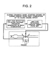
- control apparatus comprises at least a unit for retarding the ignition timing from the MBT (Minimum advance for Best Torque) to reduce exhaust emissions in an extremely early stage in startup from a time point of the first combustion up to a start of an idling of engine.
- MBT Minimum advance for Best Torque
- control apparatus further comprising:
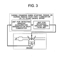
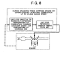
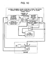
- the control apparatus comprises a unit for directly or indirectly detecting a cylinder internal pressure (combustion pressure) generated in each combustion, and for correcting (optimizing) the retard amount for each combustion in order to detect the stability limit to optimize the retard amount also during cranking when starting an engine or during a period from the first combustion up to the idling engine speed.
- control apparatus further comprising:
- the control apparatus comprises a unit for directly or indirectly detecting an angular acceleration of the engine generated in each combustion, and for correcting (optimizing) the retard amount for each combustion in order to detect the stability limit to optimize the retard amount also during cranking when starting an engine or during a period from the first combustion up to the idling engine speed. It is used the fact that from laws of motion, a correlation is present between the combustion pressure and the angular acceleration.
- control apparatus further comprising:
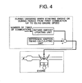
- a reference ignition timing is set to a value near the MBT and then, the retard amount is gradually increased according to the increase of the accumulated number of times of combustion strokes as times goes by. Specifically, the retard amount is relatively reduced from the first combustion up to one cycle in consideration of a start performance of the engine. Then, as the engine speed more increases to some extent and the stability of engine running is more established after engine start, the retard amount is more increased.
- control apparatus further comprising:
- a reference ignition timing is set to a value near the MBT and then the retard amount is gradually increased according to the increase of the accumulated number of times of combustion strokes.
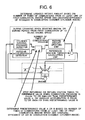
- the combustion pressure or angular acceleration of the engine generated in each combustion is detected and the next retard amount is determined based on the above value.
- the next retard amount is relatively increased.
- the combustion pressure or the angular acceleration relatively decreases, it is determined that there is no margin in the combustion and, therefore, it is considered that the next retard amount is relatively reduced, or the ignition timing is returned to the advance side.
- control apparatus further comprising:
- the combustion pressure or the angular acceleration is smaller than a predetermined value, the combustion is determined to be unstable and, therefore, the next retard amount is set to be the same as this retard amount. Alternatively, the next retard amount is returned to the reference value to definitely secure the stability.
- control apparatus further comprising:
- the combustion pressure (predetermined value A) or the angular acceleration (predetermined value B) in which the combustion is determined to be unstable is determined based on the frequency of combustions from at least one of the first combustion, the engine speed, and the charging efficiency of intake air in the combustion chamber (cylinder inside).
- the reason that the combustion pressure or angular acceleration is determined based on the number of times of combustions from the first combustion is as described above. That is, at the first combustion or in a period from the first combustion up to one cycle of engine, a level of the stability limit is relatively set to a stability side and the retardable amount is set to be reduced in consideration of the startablity of the engine. As the engine speed more increases to some extent and the stability of engine running is more established, a level of the stability limit is relatively set to an unstable side and the retardable amount is more increased.
- the reason that the combustion pressure or angular acceleration is determined based on the engine speed is also pursuant to the above-described. As described later, in the case of using the angular acceleration, as the engine speed more increases, an effect of inertia force more increases and the detection S/N ratio (sensitivity) of combustion state is more reduced. Therefore, the predetermined value B is corrected based on the engine speed.
- combustion pressure or angular acceleration is determined based on the charging efficiency is as described below. That is, since the generated combustion pressure (angular acceleration) varies due to the charging efficiency, the stability limit equivalent value, the predetermined value A, and the predetermined value B are determined in consideration of the charging efficiency.
- control apparatus further comprising:
- the stability limit equivalent value is determined based on the frequency of combustions from the first combustion or/and an engine speed or/and the charging efficiency of air in the combustion chamber (cylinder inside).
- the retard amount may be determined based on the charging efficiency.
- control apparatus further comprising:
- the control apparatus comprises a unit for determining the combustion pressure from the angular acceleration by using the fact that there is a correlation between the combustion pressure and the angular acceleration from laws of motion.
- control apparatus further comprising:
- the combustion pressure can be theoretically calculated from the angular acceleration based on the laws of motion.
- the inertia torque amount or/and friction torque amount of the engine can be considered as physical factors connecting the angular acceleration and the cylinder internal pressure.
- the inertia torque may be calculated from the engine speed.
- the friction torque may be calculated from a coolant temperature and the engine speed.
- control apparatus further comprising:
- the present invention is made in consideration of the fact that combustion robustness against the retarding of ignition timing is depending on a temperature of the working gas.
- a temperature in the combustion chamber (cylinder inside) or a temperature of the working gas is directly or indirectly detected. It is determined as to whether the retarding is performed or not based on the detected temperature values, or the retarding amount is determined based on the detected temperature values. Accordingly, more accurately making the decision, the temperature in the combustion chamber (cylinder inside) or the temperature of the working gas is preferably to be measured immediately before the spark ignition to the cylinder.
- the temperature in the combustion chamber (cylinder inside) or the temperature of the working gas may be directly detected, or indirectly detected from detection of an engine coolant temperature and an intake temperature.
- the estimation of the temperature may be performed using a model.
- control apparatus further comprising:
- the combustion robustness agaist to the retarding depends on the temperature of the working gas.
- the temperature in the combustion chamber rapidly increases from a room temperature due to heat caused by combustion. Accordingly, the retarding is not performed at least in a first cycle, because the heat caused by combustion is not sufficiently obtained and the temperature in the combustion chamber is close to the room temperature. Therefore, the retarding is performed in and after a second cycle.
- the retarding since the temperature of the working gas may not be high even in the second cycle, the retarding may preferably be performed in and after a third cycle.
- control apparatus further comprising:
- control apparatus further comprising:
- the combustion speed varies depending on the fuel property (components containing hydrocarbons).
- the combustion pressure or the angular acceleration also varies according to the combustion speed. Sensitivity to the combustion speed depending on the fuel property increases by performing the retarding. Accordingly, the fuel property can be detected by observing a relationship between the "ignition timing or retard amount", and the "combustion pressure or angular acceleration”.
- the ignition timing is retarded in an extremely early stage in startup from a time point of the first combustion up to a start of the idling of engine.
- the retard amount is determined based on the combustion pressure or the angular acceleration for each combustion.
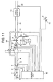
- FIG. 11 is a system chart showing the present embodiment.
- air from the outside passes through an air cleaner 1 and flows in a cylinder via an intake manifold 4 and a collector 5.
- a intake air quantity is adjusted by an electronic control throttle 3.
- An airflow sensor 2 detects the intake air quantity.
- a crank angle sensor 15 outputs by the degree a signal of a rotation angle of the crankshaft for each combustion period.
- a coolant temperature sensor 14 detects a coolant temperature of the engine.
- An accelerator pedal sensor 13 detects a depressing amount of an accelerator 6 to thereby detect a torque required by a driver.
- Each signal outputted from the accelerator pedal sensor 13, the airflow sensor 2, a throttle valve opening sensor 17 attached to the electronic throttle 3, the crank angle sensor 15, and the coolant temperature sensor 14 is transmitted to a control unit 16.
- An operation condition of the engine is obtained from signals outputted from these sensors, and a main operation amount of the engine such as an air quantity, a fuel injection amount and an ignition timing are optimally calculated.
- the fuel injection amount calculated within the control unit 16 is converted to a valve opening pulse signal and the signal is transmitted to a fuel injection valve 7. Further, a drive signal is transmitted to an ignition plug 8 such that the plug 8 is ignited at the ignition timing that is calculated by the control unit 16.
- Injected fuel is mixed with air from the intake manifold 4 and flown into the cylinder of the engine 9 to thereby form an air-fuel mixture.
- An intake valve 31 is a variable valve, and a valve opening timing and a valve closing timing can be controlled, respectively.
- the air-fuel mixture is exploded by a spark generated by the ignition plug 8 at the predetermined ignition timing and a piston is depressed by the combustion pressure, thereby obtaining motive power of the engine.
- An exhaust gas after the explosion is sent to a 3-way catalyst 11 via an exhaust manifold 10. A part of the exhaust gas is circulated to an intake side via an EGR pipe 18. A circulation amount is controlled by a valve 19.
- An A/F (air/fuel ratio) sensor 12 is attached between the engine 9 and the 3-way catalyst 11 and has linear output characteristics to an oxygen concentration contained in the exhaust gas.
- a relationship between the oxygen concentration and air/fuel ratio in the exhaust gas is almost linear and, therefore, the air/fuel ratio can be calculated based on the signal from the A/F sensor 12 that detects the oxygen concentration.
- the control unit 16 calculates the air/fuel ratio in an upstream of the 3-way catalyst 11 based on the signal outputted from the A/F sensor 12. Simultaneously, based on the signal outputted from the O 2 sensor 20, the control unit 16 calculates the oxygen concentration in a downstream of the 3-way catalyst 11, or determines whether the air/fuel ratio falls in rich or lean side relative to the stoichiometric air fuel ratio.
- the control unit 16 performs F/B (feedback) control for sequentially correcting a fuel injection amount and an intake air amount so as to optimize a purification efficiency of the 3-way catalyst using signals outputted from both the sensors. Further, an intake temperature sensor 29 detects an intake temperature and a cylinder internal pressure (combustion pressure) sensor 30 detects a cylinder internal pressure (combustion pressure), respectively.
- FIG. 12 shows an internal structure of the control unit 16.
- various sensor signals outputted from the A/F sensor 12, the throttle valve opening sensor 17, the airflow sensor 2, the crank angle sensor 15, the coolant temperature sensor 14, the accelerator pedal sensor 13, the O 2 sensor 20, an intake temperature sensor 29, and the cylinder internal pressure sensor 30 are inputted.
- an input circuit 24 subjects the signals to a signal processing such as noise reduction, and transmits the signals to an input-output port 25.
- the signals inputted to the input port are stored in a RAM 23 and subjected to an arithmetic processing in a CPU 21.
- a control program in which contents of the arithmetic processing are described is previously stored in a ROM 22.
- Signals representing the values of operating amount for the actuators, which are calculated according to the control program are stored in the RAM 23 and transmitted to the input-output port 25.
- an actuator signal supplied to an ignition plug is turned ON, whereas when no current flows therethrough, the signal is turned OFF.
- These ON/OFF signals are set.
- the ignition timing is at a time when the switching circuit is switched from ON to OFF.
- a signal for the ignition plug set in the output port is amplified in the ignition output circuit 26 to provide energy necessary and sufficient for the combustion and is transmitted to the ignition plug. Further, the ON/OFF signals for driving the fuel injection valve are set.
- a drive signal to the fuel injection valve is ON state to open the fuel injection valve, and OFF state to close the fuel injection valve.
- the drive signal is amplified in a fuel injection valve drive circuit 27 to energy sufficient for opening the fuel injection valve and is transmitted to the fuel injection valve 7.
- a drive signal for realizing a target throttle opening of the electronic throttle 3 is transmitted to the electronic throttle 3 via the electronic throttle drive circuit 28.
- the control program that is written in the ROM 22 will be described below.
- FIG. 13 is a block diagram showing the entire control system, and the system includes the following operation sections, such as "Reference ignition timing operation section” and “Retard amount operation section” ( FIG. 14 ).
- the “reference ignition timing operation section” calculates the reference ignition timing (Adv0).
- the value of Adv0 is set to be near the MBT and the calculating method is conventionally and generally used; therefore, the brief explanation will be made here.
- the reference ignition timing is calculated from the engine speed and the charging efficiency.
- the “retard amount operation section” calculates the retard amount (Rtd).
- the stability of the combustion is detected from output signals (P) from the cylinder internal pressure sensor 30, and the retard amount is gradually increased up to the stability limit.
- This operation section calculates the retard amount (Rtd) as illustrated in FIG. 14 .
- An indicated mean effective pressure (Pi) is calculated from values detected by the cylinder internal pressure sensor 30. From the charging efficiency (Ita_c) and the engine speed (Ne), a stability limit equivalent indicated mean effective pressure (Pi_us) is calculated in reference to tables.
- the charging efficiency (Ita_c) is calculated from the air amount (Qa) obtained from the airflow sensor 2 and the engine speed (Ne). Since the calculating method of the charging efficiency is the conventional technology, the detailed explanation will not be made here.
- the value of Pi is compared to the value of Pi_us. If Pi>Pi_us holds true, the combustion pressure is sufficiently high and the combustion does not reach the stability limit.
- the correction amount (dRtd) for updating retard amount is added to a previous retard correction value to obtain the latest retard amount (Rtd).
- An correction amount (dAdv) for updating retard amount is added to the previous retard correction value to obtain the latest retard amount (Rtd).
- the dRtd and the dAdv are determined from the engine speed Ne. In addition, the dAdv has a negative value. The retard amount is set to zero until the second cycle.
- the reason that the dRtd and the dAdv are determined from the Ne is as described above. That is, when the engine speed is relatively low, the retard amount is relatively small also in consideration of start performance of the engine. As the engine speed more increases to some extent and the startability is more established, the retard amount is more increased.
- the reason that the retard amount is set to zero in the first cycle is as described above. That is, the combustion robustness to the retarding depends on a temperature of the working gas. In startup, a temperature in the combustion chamber rapidly increases from the room temperature due to heat caused by the combustion. Accordingly, the retarding is not performed at least in the first cycle in which the heat caused by the combustion is not obtained and the temperature in the combustion chamber is equivalent to the room temperature. Then, the retarding is performed in and after the second cycle. In addition, since the temperature of the working gas may not be elevated also in the second cycle, the retarding may be performed in and after the third cycle.
- the stability limit due to the retarding is detected from the cylinder internal pressure (combustion pressure).
- the stability limit is detected using the crank angle signal of the engine.
- FIG. 11 is a system chart showing the present embodiment of the invention.
- a system in the present embodiment is the same as that described in the first embodiment and, therefore, the detailed descriptions will not be repeated.
- FIG. 12 shows an internal structure of the control unit 16.
- the control unit 16 in the present embodiment is the same as that described in the first embodiment and, therefore, the detailed descriptions will not be repeated.
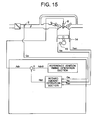
- FIG. 15 is a block diagram showing the entire control system, and the system has the operation sections including:
- the “reference ignition timing operation section” calculates the reference ignition timing (Adv0).
- the Adv0 is set to be near the MBT and the calculating method is conventionally and generally used; therefore, the detailed descriptions will not be repeated here.
- the “retard amount operation section” calculates the retard amount (Rtd).
- the angular acceleration is calculated from signals outputted from the crank angle sensor 15 and further, the cylinder internal pressure (combustion pressure) is estimated from the angular acceleration.
- the stability of the combustion is detected from the estimated cylinder internal pressure (combustion pressure), and the retard amount is gradually increased until the stability limit.
- This operation section calculates the retard amount (Rtd). Specifically, FIG. 16 shows the calculation.
- the angular acceleration (dNe) is calculated from the engine speed (Ne) calculated from signals outputted from the crank angle sensor 15.
- the angular acceleration equivalent torque (combustion pressure) is calculated by multiplying the dNe by a constant K. Then, the inertia torque amount (P_I) is subtracted from the angular acceleration equivalent torque amount and the friction torque amount (P_f) is added to the above difference to thereby obtain the indicated mean effective pressure estimate value (Pi_est).
- the P_I is calculated from the Ne in reference to tables.
- the P_f is calculated from the Ne and the Twn in reference to tables.
- the charging efficiency (Ita_c) is calculated from the air amount (Qa) obtained from the airflow sensor 2 and the engine speed (Ne). Since the calculating method of the charging efficiency is disclosed as the conventional technology, the detailed descriptions will not be repeated here.
- the Pi_est is compared to the Pi_us. If Pi_est>Pi_us holds true, the combustion pressure is sufficiently high and does not reach the stability limit. A correction updated retard amount (dRtd) is added to a previous retard correction value to obtain the latest retard amount (Rtd). On the other hand, if Pi_est ⁇ Pi_us holds true, the combustion pressure is low and reaches the stability limit. An correction advance amount (dAdv) is added to the previous retard correction value to obtain the latest retard amount (Rtd). The dRtd and the dAdv are determined from the Ne. In addition, the dAdv has a negative value. The retard amount is set to zero until the second cycle.
- the reason that the dRtd and the dAdv are determined from the Ne is as described above. That is, when the engine speed is relatively low, the retard amount is relatively small also in consideration of start performance of the engine. As the engine speed more increases to some extent and the startability is more established, the retard amount is more increased.
- the reason that the retard amount is set to zero in the first cycle is as described above. That is, the combustion robustness against to the retarding depends on a temperature of the working gas. In startup, a temperature in the combustion chamber rapidly increases from the room temperature due to heat caused by the combustion. Accordingly, the retarding is not performed at least in the first cycle in which the heat caused by the combustion is not obtained and the temperature in the combustion chamber is equivalent to the room temperature. Then, the retarding is performed in and after the second cycle. In addition, since the temperature of the working gas may not be elevated also in the second cycle, the retarding may be performed in and after the third cycle.
- the retarding is performed in and after the second cycle.
- the retarding is determined based on the temperature in the combustion chamber.
- the stability limit is detected using the crank angle signal of the engine in the same manner as in the second embodiment.
- FIG. 11 is a system chart showing the present embodiment of the invention.
- a system in the present embodiment is the same as that described in the first embodiment and, therefore, the detailed descriptions will not be repeated.
- FIG. 12 shows an internal structure of the control unit 16.
- the control unit 16 in the present embodiment is the same as that described in the first embodiment and, therefore, the detailed descriptions will not be repeated.
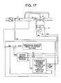
- FIG. 17 is a block diagram showing the entire control system, and the system has the operation sections including: reference ignition timing operation section; combustion chamber internal temperature estimate value operation section ( FIG. 18 ); and retard amount operation section ( FIG. 19 ).
- the “reference ignition timing operation section” calculates the reference ignition timing (Adv0).
- the Adv0 is set to be near the MBT and the calculating method is conventionally and generally used; therefore, the detailed descriptions will not be repeated here.
- the "combustion chamber internal temperature estimate value operation section” calculates the combustion chamber internal temperature estimate value (Tcyl).
- the “retard amount operation section” calculates the retard amount (Rtd).
- the angular acceleration is calculated from signals outputted from the crank angle sensor 15 and further, the cylinder internal pressure (combustion pressure) is estimated from the angular acceleration.
- the stability of the combustion is detected from the estimated cylinder internal pressure (combustion pressure), and the retard amount is gradually increased until the stability limit. However, note that whether the retarding is performed is determined based on the combustion chamber internal temperature (Tcyl).
- This operation section calculates the combustion chamber internal temperature (Tcyl). Specifically, FIG. 18 shows the calculation. Using as an argument the fuel injection amount (Ti), the basic heating value is calculated in reference to maps. The basic heating value is multiplied by the combustion air/fuel ratio correction value and the ignition timing correction value and further, the obtained product is multiplied by the heat capacity coefficient (C) and the heat conductivity coefficient (K) to thereby obtain a heating value to be supplied. Using as an argument the target air/fuel ratio (Tg_AF), a combustion air/fuel ratio correction coefficient is calculated in reference to maps. The calculating method of the Tg_AF is conventionally and generally used and, therefore, the detailed descriptions will not be repeated here.
- the above coefficient is calculated from parameters typifying operation conditions such as the engine speed and the charging efficiency (or target torque).
- the ignition timing Using as an argument the ignition timing (Adv), the ignition timing correction coefficient is calculated in reference to maps.
- the coolant temperature (Twn) Using as an argument the coolant temperature (Twn), a heating value to be radiated is calculated in reference to maps.
- the intake temperature in startup (Ths) is used as an initial value of the combustion chamber internal temperature estimate value. Then, a heat balance calculation between the heating value to be supplied and the heating value to be radiated is performed for each combustion occurrence to update the combustion chamber internal temperature estimate value.
- Each of the map values may be determined through experiments.
- This operation section calculates the retard amount (Rtd). Specifically, FIG. 19 shows the calculation.
- the angular acceleration (dNe) is calculated from the engine speed (Ne) calculated from signals outputted from the crank angle sensor 15.
- the angular acceleration equivalent torque (combustion pressure) is calculated by multiplying the dNe by a constant K. Then, the inertia torque amount (P_I) is subtracted from the angular acceleration equivalent torque amount and the friction torque amount (P_f) is added to the above difference to thereby obtain the indicated mean effective pressure estimate value (Pi_est).
- the P_I is calculated from the Ne in reference to tables.
- the P_f is calculated from the Ne and the Twn in reference to tables.
- the charging efficiency (Ita_c) is calculated from the air amount (Qa) obtained from the airflow sensor 2 and the engine speed (Ne). Since the calculating method of the charging efficiency is disclosed as the conventional technology, the detailed descriptions will not be repeated here.
- the Pi_est is compared to the Pi_us. If Pi_est>Pi_us holds true, the combustion pressure is sufficiently high and does not reach the stability limit. A correction retard amount (dRtd) is added to a previous retard correction value to obtain the latest retard amount (Rtd). On the other hand, if Pi_est ⁇ Pi_us holds true, the combustion pressure is low and reaches the stability limit. A correction advance amount (dAdv) is added to the previous retard correction value to obtain the latest retard amount (Rtd). The dRtd and the dAdv are determined from the Ne. In addition, the dAdv has a negative value.
- the reason that the dRtd and the dAdv are determined from the Ne is as described above. That is, when the engine speed is relatively low, the retard amount is relatively small also in consideration of start performance of the engine. As the engine speed more increases to some extent and the startability is more established, the retard amount is more increased.
- the reason that when Tcyl>Tcyl_rtd holds true, the retarding of the ignition timing is started is as described above. That is, the combustion robustness to the retarding depends on a temperature of the working gas. In startup, a temperature in the combustion chamber rapidly increases from the room temperature due to heat caused by the combustion. Accordingly, when Tcyl>Tcyl_rtd that represents a state where the temperature in the combustion chamber reaches a temperature at which the combustion robustness to the retarding is secured holds true, the retarding of the ignition timing is performed.
- the Tcyl_rtd may be determined through experiments.
- FIG. 11 is a system chart showing the present embodiment of the invention.
- a system in the present embodiment is the same as that described in the first embodiment and, therefore, detailed descriptions will not be repeated.
- FIG. 12 shows an internal structure of the control unit 16.
- the control unit 16 in the present embodiment is the same as that described in the first embodiment and, therefore, detailed descriptions will not be repeated.
- FIG. 20 is a block diagram showing the entire control system, and the system has the operation sections including:
- the “reference ignition timing operation section” calculates the reference ignition timing (Adv0).
- the Adv0 is set to be near the MBT and the calculating method is conventionally and generally used; therefore, the detailed descriptions will not be repeated here.
- the “retard amount operation section” calculates the retard amount (Rtd) and the stability limit arrival flag (F_us).
- This operation section calculates the retard amount (Rtd). Specifically, FIG. 21 shows the calculation.
- the indicated mean effective pressure (Pi) is calculated from values detected by the cylinder internal pressure sensor 30.
- the charging efficiency (Ita_c) is calculated from the air amount (Qa) obtained from the airflow sensor 2 and the engine speed (Ne). Since the calculating method of the charging efficiency is disclosed as the conventional technology, the detailed descriptions will not be repeated here.
- the Pi is compared to the Pi_us. If Pi>Pi_us holds true, the combustion pressure is sufficiently high and does not reach the stability limit. A correction retard amount (dRtd) is added to a previous retard correction value to obtain the latest retard amount (Rtd). On the other hand, if Pi ⁇ Pi_us holds true, the combustion pressure is low and reaches the stability limit.
- the stability limit arrival flag (F_us) is set to one and a correction updated advance amount (dAdv) is added to the previous retard correction value to obtain the latest retard amount (Rtd).
- the dRtd and the dAdv are determined from the Ne. In addition, the dAdv has a negative value. The retard amount is set to zero until the second cycle.
- the reason that the dRtd and the dAdv are determined from the Ne is as described above. That is, when the engine speed is relatively low, the retard amount is relatively small also in consideration of start performance of the engine. As the engine speed more increases to some extent and the startability is more established, the retard amount is more increased.
- the reason that the retard amount is set to zero in the first cycle is as described above. That is, the combustion robustness to the retarding depends on a temperature of the working gas. In startup, a temperature in the combustion chamber rapidly increases from the room temperature due to heat caused by the combustion. Accordingly, the retarding is not performed at least in the first cycle in which the heat caused by the combustion is not obtained and the temperature in the combustion chamber is equivalent to the room temperature. Then, the retarding is performed in and after the second cycle. In addition, since the temperature of the working gas may not be elevated also in the second cycle, the retarding may be performed in and after the third cycle.
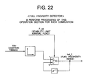
- This operation section calculates a fuel property index (Ind_f). Specifically, FIG. 22 shows the calculation.
- the fuel property index (Ind_f) is calculated in reference to tables from the ignition timing (Adv) when the stability limit arrival flag (F_us) is set to one.
- the combustion speed varies depending on the fuel property. Accordingly, the ignition timing as the stability limit varies depending on the fuel property. As described above, using this principle, the fuel property is detected in an extremely early stage in startup. The detailed descriptions will not be repeated here, but the engine may be optimally controlled according to the detected fuel property.
Landscapes
- Engineering & Computer Science (AREA)
- Theoretical Computer Science (AREA)
- Signal Processing (AREA)
- Chemical & Material Sciences (AREA)
- Combustion & Propulsion (AREA)
- Mechanical Engineering (AREA)
- General Engineering & Computer Science (AREA)
- Electrical Control Of Ignition Timing (AREA)
- Combined Controls Of Internal Combustion Engines (AREA)
Applications Claiming Priority (1)
| Application Number | Priority Date | Filing Date | Title |
|---|---|---|---|
| JP2007331313A JP5011086B2 (ja) | 2007-12-25 | 2007-12-25 | エンジンの制御装置 |
Publications (2)
| Publication Number | Publication Date |
|---|---|
| EP2075458A2 true EP2075458A2 (de) | 2009-07-01 |
| EP2075458A3 EP2075458A3 (de) | 2010-08-25 |
Family
ID=40379643
Family Applications (1)
| Application Number | Title | Priority Date | Filing Date |
|---|---|---|---|
| EP08022339A Withdrawn EP2075458A3 (de) | 2007-12-25 | 2008-12-23 | Motorsteuerungsvorrichtung |
Country Status (3)
| Country | Link |
|---|---|
| US (1) | US8033267B2 (de) |
| EP (1) | EP2075458A3 (de) |
| JP (1) | JP5011086B2 (de) |
Cited By (1)
| Publication number | Priority date | Publication date | Assignee | Title |
|---|---|---|---|---|
| WO2014155175A1 (en) * | 2013-03-27 | 2014-10-02 | Toyota Jidosha Kabushiki Kaisha | Control apparatus for internal combustion engine |
Families Citing this family (8)
| Publication number | Priority date | Publication date | Assignee | Title |
|---|---|---|---|---|
| JP4664395B2 (ja) * | 2008-05-23 | 2011-04-06 | 日立オートモティブシステムズ株式会社 | エンジンの制御装置 |
| US9115655B2 (en) | 2011-04-26 | 2015-08-25 | Allen B. Rayl | Cylinder pressure parameter correction systems and methods |
| US8983753B2 (en) | 2011-04-29 | 2015-03-17 | GM Global Technology Operations LLC | Combustion setpoint control systems and methods |
| US8600644B2 (en) * | 2011-05-23 | 2013-12-03 | GM Global Technology Operations LLC | Cylinder pressure sensor compensation systems and methods |
| US9127601B2 (en) | 2012-08-07 | 2015-09-08 | Joel Cowgill | Cylinder to cylinder balancing using fully flexible valve actuation and cylinder pressure feedback |
| JP5962463B2 (ja) * | 2012-11-27 | 2016-08-03 | 三菱自動車工業株式会社 | エンジン始動判定装置 |
| JP6208461B2 (ja) * | 2013-04-22 | 2017-10-04 | 株式会社ケーヒン | 燃料噴射弁 |
| DE102017206301B3 (de) | 2017-04-12 | 2018-06-14 | Continental Automotive Gmbh | Verfahren und Vorrichtung zum Starten einer Brennkraftmaschine mit hohem Alkoholanteil im Kraftstoff |
Citations (7)
| Publication number | Priority date | Publication date | Assignee | Title |
|---|---|---|---|---|
| JPH0264252A (ja) | 1988-08-30 | 1990-03-05 | Nissan Motor Co Ltd | 内燃機関の燃焼制御装置 |
| JPH0812209A (ja) | 1994-06-28 | 1996-01-16 | Hitachi Building Syst Eng & Service Co Ltd | エレベータの保守運転装置 |
| JPH09100741A (ja) | 1995-10-06 | 1997-04-15 | Nissan Motor Co Ltd | 内燃機関の制御装置 |
| JPH10110638A (ja) | 1996-10-04 | 1998-04-28 | Fuji Heavy Ind Ltd | エンジンの燃焼制御装置 |
| DE19918664A1 (de) | 1999-04-24 | 2000-11-02 | Bayerische Motoren Werke Ag | Verfahren zur Zündsynchronisation |
| JP2001153014A (ja) | 1999-11-24 | 2001-06-05 | Nissan Motor Co Ltd | 内燃機関の排気浄化装置 |
| JP2007001425A (ja) | 2005-06-23 | 2007-01-11 | Toyota Motor Corp | 車両およびその制御方法並びに動力出力装置 |
Family Cites Families (8)
| Publication number | Priority date | Publication date | Assignee | Title |
|---|---|---|---|---|
| JPS5578168A (en) * | 1978-12-07 | 1980-06-12 | Nippon Soken Inc | Feedback type ignition time control device for internal combustion engine |
| JP3060277B2 (ja) * | 1994-10-20 | 2000-07-10 | 株式会社ユニシアジェックス | 内燃機関の点火時期制御装置 |
| JP3326658B2 (ja) | 1994-10-27 | 2002-09-24 | 株式会社ニコン | アブソリュートエンコーダ |
| JP3965703B2 (ja) * | 1994-12-28 | 2007-08-29 | マツダ株式会社 | エンジンの排気ガス浄化装置及び排気ガス浄化方法 |
| JP3838006B2 (ja) * | 2000-09-01 | 2006-10-25 | 日産自動車株式会社 | 内燃機関の点火時期制御装置 |
| US6491024B1 (en) * | 2000-10-11 | 2002-12-10 | Ford Global Technologies, Inc. | System and method for cold start control of internal combustion engines |
| JP4560978B2 (ja) * | 2001-03-30 | 2010-10-13 | マツダ株式会社 | ターボ過給機付火花点火式直噴エンジン |
| DE10222703B4 (de) * | 2001-05-23 | 2015-06-18 | Denso Corporation | Steuergerät für eine Brennkraftmaschine |
-
2007
- 2007-12-25 JP JP2007331313A patent/JP5011086B2/ja not_active Expired - Fee Related
-
2008
- 2008-12-19 US US12/339,401 patent/US8033267B2/en not_active Expired - Fee Related
- 2008-12-23 EP EP08022339A patent/EP2075458A3/de not_active Withdrawn
Patent Citations (7)
| Publication number | Priority date | Publication date | Assignee | Title |
|---|---|---|---|---|
| JPH0264252A (ja) | 1988-08-30 | 1990-03-05 | Nissan Motor Co Ltd | 内燃機関の燃焼制御装置 |
| JPH0812209A (ja) | 1994-06-28 | 1996-01-16 | Hitachi Building Syst Eng & Service Co Ltd | エレベータの保守運転装置 |
| JPH09100741A (ja) | 1995-10-06 | 1997-04-15 | Nissan Motor Co Ltd | 内燃機関の制御装置 |
| JPH10110638A (ja) | 1996-10-04 | 1998-04-28 | Fuji Heavy Ind Ltd | エンジンの燃焼制御装置 |
| DE19918664A1 (de) | 1999-04-24 | 2000-11-02 | Bayerische Motoren Werke Ag | Verfahren zur Zündsynchronisation |
| JP2001153014A (ja) | 1999-11-24 | 2001-06-05 | Nissan Motor Co Ltd | 内燃機関の排気浄化装置 |
| JP2007001425A (ja) | 2005-06-23 | 2007-01-11 | Toyota Motor Corp | 車両およびその制御方法並びに動力出力装置 |
Non-Patent Citations (1)
| Title |
|---|
| FRANCIS T. CONNOLLY: "Modeling and identification of the combustion pressure", MECHANICAL SYSTEMS AND SIGNAL PROCESSING, 15 January 1992 (1992-01-15), University of Michigan, pages 1 - 19, XP055123163, Retrieved from the Internet <URL:http://deepblue.lib.umich.edu/bitstream/handle/2027.42/31839/0000786.pdf?sequence=1> [retrieved on 20140613] * |
Cited By (1)
| Publication number | Priority date | Publication date | Assignee | Title |
|---|---|---|---|---|
| WO2014155175A1 (en) * | 2013-03-27 | 2014-10-02 | Toyota Jidosha Kabushiki Kaisha | Control apparatus for internal combustion engine |
Also Published As
| Publication number | Publication date |
|---|---|
| US20090159042A1 (en) | 2009-06-25 |
| JP5011086B2 (ja) | 2012-08-29 |
| US8033267B2 (en) | 2011-10-11 |
| JP2009150371A (ja) | 2009-07-09 |
| EP2075458A3 (de) | 2010-08-25 |
Similar Documents
| Publication | Publication Date | Title |
|---|---|---|
| US8033267B2 (en) | Control apparatus for an engine | |
| JP5587838B2 (ja) | 内燃機関の制御装置 | |
| JP4664395B2 (ja) | エンジンの制御装置 | |
| KR101060532B1 (ko) | 내연 기관의 시동 제어 장치 | |
| US9926873B2 (en) | Internal combustion engine control apparatus | |
| CN101144435B (zh) | 发动机的控制装置 | |
| JPH11294228A (ja) | ディーゼルエンジンの燃料噴射制御装置 | |
| JP5357852B2 (ja) | 内燃機関の制御装置 | |
| JPH09287507A (ja) | 内燃機関のスロットル弁制御装置 | |
| JP3838006B2 (ja) | 内燃機関の点火時期制御装置 | |
| JP5381733B2 (ja) | 内燃機関の制御装置 | |
| JP2017223138A (ja) | 内燃機関の排気温度推定装置 | |
| JP3994465B2 (ja) | 燃料噴射時期制御装置 | |
| JPH11270386A (ja) | 内燃機関の燃料噴射制御装置 | |
| JP4415803B2 (ja) | 内燃機関の制御装置 | |
| JP2017020417A (ja) | 内燃機関の制御装置 | |
| JP7307760B2 (ja) | 推定装置 | |
| JP2000073927A (ja) | 内燃機関の燃焼状態検出装置 | |
| JP2000257476A (ja) | 筒内噴射式内燃機関の制御装置 | |
| JP2008057380A (ja) | エンジンの始動制御装置及び始動制御方法 | |
| JP2008038732A (ja) | 内燃機関の燃料制御装置 | |
| JP2005069045A (ja) | 内燃機関の燃料噴射制御装置 | |
| JP2002349408A (ja) | 内燃機関の点火時期制御装置 | |
| JP2589193B2 (ja) | 内燃機関の点火時期制御装置 | |
| JP6456273B2 (ja) | 内燃機関の制御装置 |
Legal Events
| Date | Code | Title | Description |
|---|---|---|---|
| PUAI | Public reference made under article 153(3) epc to a published international application that has entered the european phase |
Free format text: ORIGINAL CODE: 0009012 |
|
| AK | Designated contracting states |
Kind code of ref document: A2 Designated state(s): AT BE BG CH CY CZ DE DK EE ES FI FR GB GR HR HU IE IS IT LI LT LU LV MC MT NL NO PL PT RO SE SI SK TR |
|
| AX | Request for extension of the european patent |
Extension state: AL BA MK RS |
|
| PUAL | Search report despatched |
Free format text: ORIGINAL CODE: 0009013 |
|
| AK | Designated contracting states |
Kind code of ref document: A3 Designated state(s): AT BE BG CH CY CZ DE DK EE ES FI FR GB GR HR HU IE IS IT LI LT LU LV MC MT NL NO PL PT RO SE SI SK TR |
|
| AX | Request for extension of the european patent |
Extension state: AL BA MK RS |
|
| 17P | Request for examination filed |
Effective date: 20110225 |
|
| AKX | Designation fees paid |
Designated state(s): DE FR GB IT |
|
| 17Q | First examination report despatched |
Effective date: 20140624 |
|
| GRAP | Despatch of communication of intention to grant a patent |
Free format text: ORIGINAL CODE: EPIDOSNIGR1 |
|
| INTG | Intention to grant announced |
Effective date: 20160203 |
|
| STAA | Information on the status of an ep patent application or granted ep patent |
Free format text: STATUS: THE APPLICATION IS DEEMED TO BE WITHDRAWN |
|
| 18D | Application deemed to be withdrawn |
Effective date: 20160614 |