EP2075490A2 - Fahrzeugsteuerungssystem - Google Patents
Fahrzeugsteuerungssystem Download PDFInfo
- Publication number
- EP2075490A2 EP2075490A2 EP08020259A EP08020259A EP2075490A2 EP 2075490 A2 EP2075490 A2 EP 2075490A2 EP 08020259 A EP08020259 A EP 08020259A EP 08020259 A EP08020259 A EP 08020259A EP 2075490 A2 EP2075490 A2 EP 2075490A2
- Authority
- EP
- European Patent Office
- Prior art keywords
- range
- instruction signal
- shift
- instruction
- signal
- Prior art date
- Legal status (The legal status is an assumption and is not a legal conclusion. Google has not performed a legal analysis and makes no representation as to the accuracy of the status listed.)
- Granted
Links
Images







Classifications
-
- F—MECHANICAL ENGINEERING; LIGHTING; HEATING; WEAPONS; BLASTING
- F16—ENGINEERING ELEMENTS AND UNITS; GENERAL MEASURES FOR PRODUCING AND MAINTAINING EFFECTIVE FUNCTIONING OF MACHINES OR INSTALLATIONS; THERMAL INSULATION IN GENERAL
- F16H—GEARING
- F16H61/00—Control functions within control units of change-speed- or reversing-gearings for conveying rotary motion ; Control of exclusively fluid gearing, friction gearing, gearings with endless flexible members or other particular types of gearing
- F16H61/12—Detecting malfunction or potential malfunction, e.g. fail safe ; Circumventing or fixing failures
-
- F—MECHANICAL ENGINEERING; LIGHTING; HEATING; WEAPONS; BLASTING
- F16—ENGINEERING ELEMENTS AND UNITS; GENERAL MEASURES FOR PRODUCING AND MAINTAINING EFFECTIVE FUNCTIONING OF MACHINES OR INSTALLATIONS; THERMAL INSULATION IN GENERAL
- F16H—GEARING
- F16H59/00—Control inputs to control units of change-speed- or reversing-gearings for conveying rotary motion
- F16H59/02—Selector apparatus
- F16H59/0204—Selector apparatus for automatic transmissions with means for range selection and manual shifting, e.g. range selector with tiptronic
-
- F—MECHANICAL ENGINEERING; LIGHTING; HEATING; WEAPONS; BLASTING
- F16—ENGINEERING ELEMENTS AND UNITS; GENERAL MEASURES FOR PRODUCING AND MAINTAINING EFFECTIVE FUNCTIONING OF MACHINES OR INSTALLATIONS; THERMAL INSULATION IN GENERAL
- F16H—GEARING
- F16H59/00—Control inputs to control units of change-speed- or reversing-gearings for conveying rotary motion
- F16H59/02—Selector apparatus
- F16H59/08—Range selector apparatus
- F16H59/12—Range selector apparatus comprising push button devices
-
- F—MECHANICAL ENGINEERING; LIGHTING; HEATING; WEAPONS; BLASTING
- F16—ENGINEERING ELEMENTS AND UNITS; GENERAL MEASURES FOR PRODUCING AND MAINTAINING EFFECTIVE FUNCTIONING OF MACHINES OR INSTALLATIONS; THERMAL INSULATION IN GENERAL
- F16H—GEARING
- F16H61/00—Control functions within control units of change-speed- or reversing-gearings for conveying rotary motion ; Control of exclusively fluid gearing, friction gearing, gearings with endless flexible members or other particular types of gearing
- F16H61/26—Generation or transmission of movements for final actuating mechanisms
- F16H61/28—Generation or transmission of movements for final actuating mechanisms with at least one movement of the final actuating mechanism being caused by a non-mechanical force, e.g. power-assisted
- F16H61/32—Electric motors , actuators or related electrical control means therefor
-
- F—MECHANICAL ENGINEERING; LIGHTING; HEATING; WEAPONS; BLASTING
- F16—ENGINEERING ELEMENTS AND UNITS; GENERAL MEASURES FOR PRODUCING AND MAINTAINING EFFECTIVE FUNCTIONING OF MACHINES OR INSTALLATIONS; THERMAL INSULATION IN GENERAL
- F16H—GEARING
- F16H61/00—Control functions within control units of change-speed- or reversing-gearings for conveying rotary motion ; Control of exclusively fluid gearing, friction gearing, gearings with endless flexible members or other particular types of gearing
- F16H61/26—Generation or transmission of movements for final actuating mechanisms
- F16H61/28—Generation or transmission of movements for final actuating mechanisms with at least one movement of the final actuating mechanism being caused by a non-mechanical force, e.g. power-assisted
- F16H61/32—Electric motors , actuators or related electrical control means therefor
- F16H2061/326—Actuators for range selection, i.e. actuators for controlling the range selector or the manual range valve in the transmission
Definitions
- This invention relates to a vehicle control system for controlling an automatic transmission of a vehicle.
- a conventional vehicle control system changes over a shift range of an automatic transmission of a vehicle through by-wire control in response to an output signal from an operation unit operated by a vehicle driver.
- the output signal instructs the shift range to the automatic transmission of the vehicle.
- abnormal signals are input to a by-wire control part from the operation unit due to defective operation of the operation unit or defective communication between the operation unit and the by-wire control part. Such abnormal signals will cause an unnecessary change over to a shift range different from the one instructed by the driver or make it difficult to change over the shift range as instructed.
- JP-B-5-43904 proposes enhancing fail-safe performance by using an emergency switch attached to an operation unit in case the operation unit becomes defective.
- this emergency switch is operated only in case a trouble has occurred.
- This is additionally incorporated in the operation unit and raises the cost.
- this technology can cope with the trouble in the operation unit but cannot cope with the defective communication between the operation unit and the by-wire control part, and is not still satisfactory from the standpoint of fail-safe performance. Addition of a function for dealing with the defective communication further raises the cost.
- a vehicle control system for an automatic transmission of a vehicle comprises a first operation part, a second operation part and a by-wire control part.
- the first operation part is operable for issuing an instruction for shifting a range of an automatic transmission of a vehicle, and outputting a first instruction signal representing an instruction for shifting the range.
- the second operation part is operable separately from the first operation part for issuing an instruction concerning an additional function added to essential functions that are essential for driving the vehicle, and outputting a second instruction signal representing an instruction related to the additional function.
- the by-wire control part controls the change-over of the shift range according to a reference signal which is the first instruction signal input from the first operation part.
- the by-wire control part monitors the first instruction signal input from the first operation part, and uses the second instruction signal input from the second operation unit as the reference signal if the first instruction signal is determined to be abnormal.
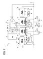
- a vehicle control system 1 is mounted on a vehicle (not shown) together with an engine 5 and an automatic transmission 2.
- the vehicle control system 1 is provided with a shift control device 10, a range control device 20, a meter device 30 and an engine control device 50.
- the engine control device 50 includes an engine switch 52, engine sensors 54 and an engine control circuit 58.
- the engine switch 52 is an ignition switch for instructing the on/off of the engine 5, and provided in front of a driver's seat in the vehicle. This engine switch 52 is manually operable by the driver or can be remotely operated by using an electronic key.
- the engine switch 52 outputs an on-signal when it is turned on and outputs an off-signal when it is turned off. Therefore, depending on its operation, the engine switch 52 outputs a switch instruction signal representing an on instruction or an off instruction for the engine 5.
- the engine sensors 54 detect the operating conditions of the engine 5 based on the opening degree of an intake throttle, and operation timings of fuel injectors and an igniter.
- the engine control circuit 58 is an electronic circuit including a microcomputer, and is directly connected to the engine switch 52 and to the engine sensors 54 to communicate therewith. Upon receipt of a switch instruction signal representing the on-instruction from the engine switch 52, the engine control circuit 58 starts the engine 5 and, thereafter, controls the engine 5 based on the input signals from the engine sensors 54. Upon receipt of a switch instruction signal representing the off-instruction from the engine switch 52, on the other hand, the engine control circuit 58 stops the engine 5 and stands ready for the next start.
- the shift control device 10 includes a hydraulic circuit 12, a range shifter 16 and a shift control circuit 18.
- the hydraulic circuit 12 is constructed with a manual valve 13 and a plurality of electromagnetic valves 14.
- the manual valve 13 is a spool valve and works to change over the shift range of the automatic transmission 2 based on the output hydraulic pressure that varies depending on the moving position of the spool (not shown) that reciprocally moves.
- the automatic transmission 2 provides two kinds of traveling ranges, i.e., a forward drive range (D) and a reverse drive range (R) as shift ranges for transmitting the rotational output of the engine 5 to the drive wheels of the vehicle.
- the automatic transmission 2 further, provides two kinds of non-traveling ranges, i.e., a parking range (P) and a neutral range (N) as shift ranges for not transmitting the rotational output of the engine 5 to the drive wheels of the vehicle.
- the electromagnetic valves 14 drive the corresponding shift moving elements (not shown) in the automatic transmission 2 depending on the hydraulic output.
- the automatic transmission 2 is a stepped shift system, in which friction elements such as clutches and brakes which are shift moving elements are tightened or released by the corresponding electromagnetic valves 14, so that the transmission gear ratio in the D-range changes over stepwise.
- the range shifter 16 is constructed by a shift-up switch 16U for instructing the automatic transmission 2 to change the transmission gear ratio up and a shift-down switch 16D for instucting the automatic transmission 2 to change the transmission gear ratio down.
- the shift switches 16U and 16D are button switches as illustrated in Fig. 1 or arm switches that are provided on a steering wheel 4 in front of the driver's seat in the vehicle and independently and manually operable by the driver, and produces on-signals when turned on and produces off-signals in other cases. When operated, therefore, the shift switches 16U and 16D output the shift instruction signals representing an up-instruction or a down-instruction concerning the transmission gear ratio.
- the shift control circuit 18 is an electronic circuit including a microcomputer and has a memory 18a.
- the shift control circuit 18 is directly connected to the electromagnetic valves 14 of the hydraulic circuit 12 and to the shift switches 16U and 16D so as to be communicable therewith, and is connected to the engine control circuit 58 and to a vehicle speed sensor 3 through an in-vehicle LAN 6 to be communicable therewith.
- the vehicle speed sensor 3 detects the speed of the vehicle based on the rotational speed of a transmission shaft of the automatic transmission 2.
- the shift control circuit 18 selectively realizes an automatic shift mode for automatically changing over the transmission gear ratio of the automatic transmission 2 as a function essential for the vehicle and a manual shift mode for manually changing over the transmission gear ratio of the automatic transmission 2 as an additional function of the vehicle added to the essential function.
- the transmission gear ratio of the automatic transmission 2 is so changed over as to comply with a shift map stored in the memory 18a based on the engine operating condition represented by an input signal from the engine sensors 54 through the engine control circuit 58 and upon a vehicle speed represented by an input signal from the vehicle speed sensor 3.
- the transmission gear ratio of the automatic transmission 2 is changed over depending on the up-instruction or the down-instruction represented by the shift instruction signal input from the shift switch 16U or 16D.
- the shift mode is selected by operating a predetermined operation member provided near the driver's seat in the vehicle.
- the range control device 20 includes a range selector 22, a shift actuator 26, a motion conversion mechanism 27, a rotational position sensor 29 and a range control circuit 28.
- the range selector 22 is constructed by a selector lever 23, range switches 24P, 24R, 24N, 24D, and a range output device 25.
- the selector lever 23 is provided in front of or by the side of the driver's seat in the vehicle, and is manually operable by the driver to select a shift range.
- Four shift positions P, R, N and D corresponding to the P-, R-, N- and D-shift ranges are set for the selector lever 23 as operation positions for instructing a shift range for the automatic transmission 2.
- the range switches 24P, 24R, 24N and 24D are contact switches or non-contact switches provided near the selector lever 23, and output an on-signal upon detecting the selector lever 23 operated to the shift position P, R, N or D, and output an off-signal in other cases.
- the range output device 25 is directly connected to the range switches 24P, 24R, 24N and 24D so as to be communicable therewith. Based on the signals input from the range switches 24P, 24R, 24N and 24D, the range output device 25 so forms an output signal as to identify the present shift position of the selector lever 23 among the shift positions P, R, N and D depending on the duty ratio. Therefore, the range output device 25 outputs a range instruction signal representing a selected range (instructed range) instructed by the operation of the selector lever 23 among the shift ranges P, R, N and D.
- the shift actuator 26 is an electric actuator constructed by an electric motor and a reduction mechanism, and produces a rotational output to a rotary shaft 26a upon being fed with an electric current.
- a motion conversion mechanism 27 converts the rotational output produced on the rotary shaft 26a into a linear output of the spool of the manual valve 13. Therefore, the shift range of the automatic transmission 2 is changed over depending on the rotational position of the rotary shaft 26a. Therefore, the shift actuator 26 is provided with a rotational position sensor 29 for detecting the shift range (actual range) which is now being realized in the automatic transmission 2 based on the rotational position of the rotary shaft 26a.
- the range control circuit 28 is an electronic circuit including a microcomputer, and has a memory 28a.
- the range control circuit 28 is directly connected to the range output device 25, shift actuator 26, rotational position sensor 29 and shift control circuit 18 so as to be communicable therewith.
- the range control circuit 28 is, further, connected to the engine control circuit 58, vehicle speed sensor 3, foot brake sensor 7, parking brake sensor 8 and accelerator sensor 9 through the in-vehicle LAN 6 to be communicable therewith.
- the foot brake sensor 7 is provided near a brake pedal 7a in front of the driver's seat in the vehicle, and detects if the foot brake of the vehicle is in the state of on or off accompanying the operation of the pedal 7a.
- the parking brake sensor 8 is provided near a brake lever 8a by the side or in front of the driver's seat in the vehicle, and detects if the parking brake of the vehicle is in the state of on or off accompanying the operation of the lever 8a.
- the accelerator sensor 9 is provided near an accelerator pedal 9a in front of the driver's seat in the vehicle, and detects if the accelerator of the vehicle is in the state of on or off accompanying the operation of the pedal 9a.
- the range control circuit 28 controls the shift actuator 26 so that the actual range represented by the signal input from the rotational position sensor 29 is brought into agreement with the instructed range represented by the range instruction signal. Therefore, in case the instructed range represented by a normal range instruction signal varies, the rotary shaft 26a rotates to a position corresponding to the instructed range after being varied, and the actual range is changed over to the instructed range. That is, the shift range change-over control of this embodiment is based on a shift-by-wire system which uses the range instruction signal as a reference signal and is realized electrically responsive to the reference signal.
- the range control circuit 28 controls the shift actuator 26 based on the input signals from the shift switches 16U, 16D and the engine switch 52 and upon the input signals from the sensors 3, 7, 8 and 9 through the shift control circuit 18 and the engine control circuit 58 as will be described later in detail.
- the meter device 30 includes a meter part (display part) 32, an acoustic part 34 and a meter control circuit 38.
- the meter part 32 is an analog meter or a digital meter provided in front of the driver's seat in the vehicle, and displays the status information, such as the speed of the vehicle, shift range of the automatic transmission 2, etc.
- the acoustic part 34 shown in Fig. 1 is constructed by a speaker and provided in front of the driver's seat in the vehicle, so that it produces an acoustic output of predetermined information in the vehicle.
- the meter control circuit 38 is an electronic circuit including a microcomputer and is directly connected to the meter part 32 and to the acoustic part 34 to be communicable therewith.
- the meter control circuit 38 is further connected to the vehicle speed sensor 3 and to the range control circuit 28 via the in-vehicle LAN 6 to be communicable therewith.
- the meter control circuit 38 controls the operations of the meter part 32 and the acoustic part 34 based on the input signals and the like from the vehicle speed sensor 3 and the range control circuit 28.
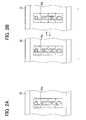
- a shift range which the meter control circuit 38 indicates on the meter part 32 according to the input signal from the range control circuit 28 is provided by an indicator 32a that continuously lights to indicate the actual range among the shift ranges P, R, N and D as shown in Fig. 2A provided the range instruction signal is normal.
- the shift range is indicated by the flashing (intermittent lighting) of the indicator 32a as shown in Fig. 2B .
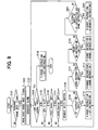
- the range control circuit 28 is programmed to execute fail-safe control according to a computer program stored in the memory 28a.
- the fail-safe control commences when a switch instruction signal representing an on-instruction is input from the engine switch 52 to the range control circuit 28 through the engine control circuit 58.
- a range instruction signal input from the range output device 25 is monitored to check if the range instruction signal is abnormal.
- the range instruction signal is determined to be normal if its duty ratio is a value representing a shift range of any one of P, R, N and D as an instruction range, and is determined to be abnormal in other cases.
- the duty ratios are, desirably, so set as to represent the shift ranges with discrete vaiues which are not smaller than 0% for discriminating breakage of wire or short circuit but which are not larger than 100%.
- the shift ranges may be represented by physical quantities such as signal frequencies or signal potentials other than the duty ratios of range instruction signals. In this case, the normal or abnormal condition may be determined based on the physical quantities.
- step S101 If determined to be normal at step S101, the shift actuator 26 executes the change-over control according to the above range instruction signal and the indicator 32a lights on according to the control signal input to the meter control circuit 38. If determined to be abnormal at step S101, the routine proceeds to step S102.
- the range instruction signal input from the range output apparatus 25 is invalidated.
- the control signal is input to the meter control circuit 38 to control the meter part 32 and the acoustic part 34 to thereby alarm an abnormal range instruction signal to the driver and passengers.
- the actual range indicated by the indicator 32a of the meter part 32 is switched to a flashing indication which is different from the normal continuous indication, the fact of abnormal condition is produced as a voice guidance from the acoustic part 34, and an alarm is generated to alarm abnormality.
- the abnormal condition may be alarmed only by either switching the indication by the indicator 32a or by the voice guidance by the acoustic part 34.
- the abnormal condition may be alarmed by changing the color or shape of indicating the actual range by the indicator 32a from the normal ones.
- the abnormal condition may be alarmed by outputting a buzzer sound or a tune from the acoustic part 34.
- step S104 it is checked whether a switch instruction signal representing the off-instruction for the engine 5 is input from the engine switch 52 through the engine control circuit 58. If the determination is negative, the routine proceeds to step S105.
- a vehicle speed SPD represented by the detection signal input from the vehicle speed sensor 3 is monitored to check if the vehicle speed is lower than a preset threshold value Sth.
- a preset threshold value Sth a preset threshold value
- step S106 further, on or off of the foot brake represented by the detection signal input from the foot brake sensor 7 is monitored to check if the foot brake is in the on state.
- step S107 further, on or off of the accelerator represented by the detection signal input from the accelerator sensor 9 is monitored to check if the accelerator is in the off state.
- step S104 If the determination is negative at any of steps S105 to S107 indicating that the vehicle is traveling normally, the routine returns to step S104. On the other hand, if the determinations are all affirmative at steps S105 to S107, i.e., the vehicle speed is lower than the preset threshold value, the foot brake is on and the accelerator is off, then the routine proceeds to step S108.
- the preset threshold value Sth of the vehicle speed is a speed at which the shift range can be safely changed over, e.g., a very low value such as 10 km/h.
- the vehicle condition in which the vehicle speed can be determined to be lower than the preset threshold value includes not only a very low-speed traveling condition of a speed of lower than the preset threshold value but also a travel-halting condition of zero speed.
- step S108 to which the routine has proceeded after the determinations are all affirmative at steps S105 to S107, the shift control circuit 18 is requested to respond.
- step S109 it is checked whether a shift instruction signal representing an up-instruction for the transmission gear ratio is input from the shift-up switch 16U through the shift control circuit 18 in response to the request at step S108.
- step S109 of this embodiment so determines that the shift instruction signal of up-instruction is input if the shift instruction signals from the shift-up switch 16U continues to be on-signals discretely more than a preset number of times or continuously for longer than a preset period of time.
- the preset number of times and the preset period of times that serve as references for determination are, for example, 5 times and 3 seconds, respectively.
- step S109 If the determination is affirmative at step S109, i.e., if the shift instruction signal representing the up-instruction is input due to the on operation of the shift-up switch 16U, the routine proceeds to step S110.
- the on operation of the shift-up switch 16U is assigned to instructing the D-range; i.e., the shift instruction signal of the up-instruction is used, instead, as a range instruction signal for D-range instruction.
- the shift actuator 26 is so controlled that the actual range represented by the input signal from the rotational position sensor 29 becomes the D-range and, therefore, the actual range is changed over to the D-range.
- the control signal is input to the meter control circuit 38 accompanying the change-over of the actual range to thereby control the meter part 32 and to change the indicator 32a over to flashing indication of the D-range.
- step S111 it is checked whether the shift instruction signal representing the down-instruction for the transmission gear ratio is input from the shift-down switch 16D through the shift control circuit 18 in response to the request at step S108. Specifically, step S111 of this embodiment so determines that the shift instruction signal of down-instruction is input if the shift instruction signals from the shift-down switch 16D continues to be on-signals discretely more than a preset number of times or continuously for longer than a preset period of time. The preset number of times and the preset period of times that serve as references for determination are as described for the case of step S109 above.
- step S111 determines whether the shift instruction signal representing the down-instruction is input due to the on operation of the shift-down switch 16D.
- the routine proceeds to step S112.
- the on operation of the shift-down switch 16D is assigned to instructing the R-range; i.e., the shift instruction signal of the down-instruction is used, instead, as the range instruction signal for R-range instruction.
- the shift actuator 26 is so controlled that the actual range represented by the input signal from the rotational position sensor 29 becomes the R-range and, therefore, the actual range is changed over to the R-range.
- the control signal is input to the meter control circuit 38 accompanying the change-over of the actual range to thereby control the meter part 32 and to change the indicator 32a over to flashing indication of the R-range.
- step S113 it is checked whether the output signal representing the change from the on state to the off state of the parking brake is input from the parking brake sensor 8, i.e., if the brake instruction signal for instructing the on of parking brake is input by the operation of the brake lever 8a.
- step S114 the on operation of the parking brake is assigned to instructing the P-range; i.e., the brake instruction signal of the on-instruction is used, instead, as the range instruction signal for P-range instruction.
- the shift actuator 26 is so controlled that the actual range represented by the input signal from the rotational position sensor 29 becomes the P-range and, therefore, the actual range is changed over to the P-range.
- the control signal is input to the meter control circuit 38 accompanying the change-over of the actual range to thereby control the meter part 32 and to change the indicator 32a over to the flashing indication of the P-range.
- step S113 determines whether the determination is negative at step S113 and after steps S110, S112 and S114 are executed. If the determination is negative at step S113 and after steps S110, S112 and S114 are executed, the routine returns to step S104 to wait for the next change-over of range.
- step S104 determines whether the switch instruction signal representing the off-instruction is input from the engine switch 52. If the determination at step S104 is affirmative, i.e., if the switch instruction signal representing the off-instruction is input from the engine switch 52, the routine proceeds to step S115.
- step S115 the off operation of the engine switch 52 is assigned to instructing the P-range, and the switch instruction signal of off-instruction is used, instead, as the range instruction signal for instructing the P-range. Namely, the shift actuator 26 is so controlled that the actual range represented by the input signal from the rotational position sensor 29 becomes the P-range and, therefore, the actual range is changed over to the P-range. Thereafter, the fail-safe control ends.
- the range shifter 16 is used instead, making it possible to instruct the D-range and the R-range that are particularly necessary for driving the vehicle.
- the automatic transmission operation can be reliably continued by controlling the automatic transmission 2 by the shift control circuit 18. It is allowed to continuously travel the vehicle by automatically changing the automatic transmission to the D-range or the R-range.
- the shift switches 16U and 16D in the range shifter 16 are operated separately from the selector lever 23 that instructs the D-range and the R-range, and are provided on the steering wheel 4 for easy operation from the standpoint of their function for instructing the shift-up and shift-down of the transmission gear ratio.
- the shift switches 16U and 16D are independent from each other, and are likely to be seldom operated erroneously. Therefore, even in case abnormal condition may occur, the transmission can be properly changed over to the D-range or the R-range maintaining operability comparable to that of when the selector lever 23 is operated, and the vehicle can be safely driven forward or reverse.
- the P-range can be instructed by using the brake lever 8a for the parking brake, instead, that is operated separately from the selector lever 23.
- the parking brake is turned on at the time of parking upon operating the brake lever 8a. Therefore, the P-range can be instructed simultaneously with the parking by using the lever 8a, instead. Even in case abnormal condition occurs, therefore, the transmission can be properly changed over to the P-range maintaining operability more reliable than that of operating the selector lever 23, and the vehicle can be safely parked.
- the instruction of range by using the substitute elements 16, 8a is permitted only in the case of a low-speed traveling state in which the vehicle speed is lower than the preset threshold value or a travel-halting state in which the foot brake is on and the accelerator pedal is off, i.e., only in the case where the safety of the vehicle is maintained. Therefore, even in case the shift range is changed over due to erroneous operation of the substitute elements 16U, 16D, 8a, the driver is allowed to cope with the erroneous operation in a state where the safety of the vehicle is maintained to a sufficient degree.
- the P-range can be automatically instructed accompanying the off operation of the engine switch 52 that is operated separately from the selector lever 23. Therefore, the P-range is realized simultaneously with the turning off of the engine switch 52. This ovoids such an occurrence that it is not allowed to start the engine 5 next time since the shift range is other than the P-range.
- the operation of the vehicle can be continued despite abnormal range instruction signal owing to the reliable fail-safe countermeasure minimizing an increase in the cost for the fail-safe countermeasure.
- the continued operation of the vehicle is achieved by the change-over to the shift range of D, R or P and by the automatic shift of the automatic transmission 2. In case abnormal condition has occurred, therefore, the passenger is allowed to drive the vehicle to a workshop or to a safe place to repair the vehicle.
- the range selector 22 corresponds to a first operation part
- the range instruction signal output from the range output device 25 of the range selector 22 corresponds to a first instruction signal
- the range shifter 16 corresponds to a second operation part
- the shift-up switch 16U of the range shifter 16 corresponds to an up-operation member
- the shift-down switch 16D of the range shifter 16 corresponds to a down-operation member
- shift instruction signals output from the shift switches 16U, 16D of the range shifter 16 correspond to a second instruction signal.
- the range control circuit 28 for executing step S101 corresponds to signal monitoring means
- the range control circuit 28 for executing steps S101, S102 and S104 to S115 corresponds to substitute processing means
- the brake lever 8a and the parking brake sensor 8 corresponds to parking brake operation part
- the engine switch 52 corresponds to a switch operation part.
- the vehicle speed sensor 3 and the range control circuit 28 for executing step S105 correspond to speed monitoring means.
- the brake pedal 7a, the foot brake sensor 7 and the range control circuit 28 for executing step S106 correspond to foot brake-monitoring means.
- the accelerator pedal 9a, the accelerator sensor 9 and the range control circuit 28 for executing step S107 correspond to accelerator-monitoring means.
- the meter device 30 and the range control circuit 28 for executing steps S101 and S103 correspond to alarm means. Further, the range control circuit 28, shift actuator 26, motion conversion mechanism 27, meter device 30, pedals 7a and 9a, and sensors 3, 7 and 9 correspond to a by-wire control part.
- a second embodiment is a modification of the first embodiment.
- the range selector 22 of the range control device 20 is not provided with the range output device 25, but the range switches 24P, 24R, 24N and24D are directly and independently connected to the range control circuit 28. Therefore, the range control circuit 28 recognizes the signals individually input thereto from the range switches 24P, 24R, 24N and 24D as range instruction signals for instructing the shift ranges of P, R, N and D.
- the fail-safe control at step S101 determines that the range instruction signal is normal if the on-signal is input from any one of the range switch 24P, 24R, 24N or 24D. In case the on-signals are simultaneously input from two or more of the range switches 24P, 24R, 24N and 24D or in case the off-signals are input from all of these range switches, the range instruction signal is determined to be abnormal.
- step S102 After determined to be abnormal, the routine proceeds to step S102. Therefore, the same operation and effect as those of the first embodiment can be enjoyed despite a fault in the range switches 24P, 24R, 24N and 24D or a defective communication between these switches and the control circuit 28.
- the range selector 22 corresponds to a first operation part, and a range instruction signal output from the range switch 24P, 24R, 24N or 24D of the range selector 22 corresponds to a first instruction signal.
- a third embodiment is a modification of the first embodiment.
- the routine proceeds to step S301 after having executed step S103 that alarms abnormal condition.
- the shift instruction signals input from the shift switches 16U and 16D are monitored and are checked to be normal or not. Specifically, at step S301, the shift instruction signal is determined to be normal if the on-signal is input from either one of the shift switch 16U or 16D only. On the other hand, the shift instruction signal is determined to be abnormal if the on-signals are simultaneously input from both of the shift switches 16U and 16D or if the off-signals are input from both of them.
- the abnormal shift instruction signal is alarmed to the driver at step S302 in the similar manner as step S103 and, thereafter, the fail-safe control ends. Therefore, in case the shift instruction becomes abnormal due to a fault in the shift switches 16U, 16D or due to a defective communication between these switches and the control circuit 28, the shift range is prohibited from being changed over and safety of the vehicle is maintained primarily.
- step S301 if the determination is rendered to be normal at step S301, it means that the shift range can be properly changed over by the shift switches 16U and 16D, and the routine proceeds to step S104 making it possible to effect a proper fail-safe countermeasure.
- the range control circuit 28 for executing steps S101 and S301 corresponds to signal monitoring means.
- a fourth embodiment is a modification of the first embodiment.
- the routine proceeds to step S401 if the determination is negative at step S113.
- step S401 it is checked whether shift instruction signals of up-instruction and down-instruction are simultaneously input for longer than a predetermined period of time from the shift switches 16U and 16D in response to the request given to the shift control circuit 18 at step S108. It is checked whether the shift instruction signals of the up-instruction and the down-instruction are simultaneously input as signals representing simultaneous receipt from the shift switches 16U and 16D that have simultaneously received the on-operation.
- the time for simultaneously inputting the shift instruction signals of up-instruction and down-instruction that serves as a reference of determination is set to be, for example, 3 seconds.
- step S401 the routine proceeds to step S402, where the on-operations simultaneously received by the shift switches 16U and 16D are assigned to instructing the N-range; i.e., the shift instruction signal representing the simultaneous receipt is used, instead, as the range instruction signal for instructing the N-range. Therefore, the shift actuator 26 is so controlled that the actual range represented by the input signal from the rotational position sensor 29 becomes the N-range and, therefore, the actual range is changed over to the N-range.
- step S402 the control signal is input to the meter control circuit 38 accompanying the change-over of the actual range to thereby control the meter part 32 and to change the indicator 32a over to the flashing indication of the N-range.
- the routine returns to step S104 and waits for the next change-over of the range in case the determination is negative at step S401 and after steps S402, S110, S112 and S114 have been executed.
- the transmission can be safely changed over to the N-range by simultaneously operating the shift switches 16U and 16D that are provided independently of each other. Therefore, even if the range instruction signal becomes abnormal, change-over to all of the shift ranges P, R, N and D can be realized guaranteeing a sufficient degree of fail-safe countermeasure at a low cost.
- the range control circuit 28 for executing steps S101, S102, S104 to S115, S401 and S402 corresponds to substitute processing means.
- a fifth embodiment is a modification of the fourth embodiment.
- a range shifter 16 is constructed by a shift switch 16UD.
- the shift switch 16UD is an arm switch that is provided on the steering wheel 4 of the vehicle and can be manually operated by the driver.
- the shift switch 16UD produces an on-signal on the positive potential side when it is tilted up as shown in Fig. 8A for shifting up the transmission gear ratio, produces an on-signal on the negative potential side when it is tilted down as shown in Fig. 8B for shifting down the transmission gear ratio, and produces an off-signal in other cases. Therefore, depending on its operation, the shift switch 16UD produces the shift instruction signal representing the up-instruction or the down-instruction for the transmission gear ratio.
- the fail-safe control at step S501 that substitutes for step S401 checks whether the shift instruction signals of up-instruction and down-instruction are alternately input each by a predetermined number of times from the shift switch 16UD responsive to a request given to the shift control circuit 18 at step S108. It is checked whether the shift instruction signals of up-instruction and down-instruction are alternately input as signals representing alternate receipts from the shift switch 16UD that has alternately received the tilt-up operation and the tilt-down operation.
- the number of times of inputting the shift instruction signals of up-instruction and down-instruction that serves as a reference of determination is set to be, for example, 3 times.
- step S501 the routine proceeds to step S502 that substitutes for step S402.
- step S502 the tilt-up operation and the tilt-down operation alternately received by the shift switch 16UD are assigned to instructing the N-range; i.e., the shift instruction signal representing the alternate receipt is used, instead, as the range instruction signal for instructing the N-range. Therefore, the actual range is changed over to the N-range, and the indicator 32a is changed over to the flashing indication of the N-range.
- the fifth embodiment even when the operation for up-instruction and the operation for down-instruction cannot be simultaneously received by the shift switch 16UD, these operations are alternately received and used to safely change the transmission over to the N-range. Therefore, the fifth embodiment, too, guarantees a sufficient degree of fail-safe countermeasure at a low cost.
- the range shifter 16 corresponds to a second operation part
- the shift instruction signal output from the shift switch 16UD of the range shifter 16 corresponds to a second instruction signal
- the range control circuit 28 for executing steps S101, S102, S104 to S115, S501 and S502 corresponds to substitute processing means.
- a sixth embodiment is a modification of the first embodiment.
- the routine proceeds to step S601 after having executed step S108 that requests a response to the shift control circuit 18.
- step S601 it is checked whether the shift instruction signal representing the down-instruction is input from the shift-down switch 16D. Specifically, if the shift instruction signal from the shift-down switch 16D is the on-signai, step S601 so determines that the shift instruction signal representing the down-instruction is input.
- step S601 If the determination is negative at step S601, the routine returns to step S104. If the determination is affirmative at step S601, however, the routine proceeds to step S602. At step S602, a response is requested to the meter control circuit 38. At next step S603, further, it is checked whether the present shift range for which the indicator 32a of the meter part 32 is selectively flashing differently from that of the normal condition (selectively indicated range) is the P-range based on the input signal from the meter control circuit 38 responsive to the request of response at step S602.
- step S603 the routine proceeds to step S604.
- step S604 the control signal is input to the meter control circuit 38 to control the meter part 32, and the range selectively indicated by the indicator 32a is changed from the P-range over to the R-range. If the determination is negative at step S603, on the other hand, the routine proceeds to step S605.
- step S605 it is checked whether the range selectively indicated by the indicator 32a is the N-range based on the input signal from the meter control circuit 38 responsive to the request of response at step S602.
- step S605 the routine proceeds to step S606.
- step S606 the control signal is input to the meter control circuit 38 to control the meter part 32, and the range selectively indicated by the indicator 32a is changed from the N-range over to the D-range. If the determination is negative at step S605, on the other hand, the routine proceeds to step S607.
- step S607 it is checked whether the range selectively indicated by the indicator 32a is the D-range based on the input signal from the meter control circuit 38 responsive to the request of response at step S602.
- step S607 the routine proceeds to step S608.
- step S608 the control signal is input to the meter control circuit 38 to control the meter part 32, and the range selectively indicated by the indicator 32a is changed from the D-range over to the P-range. If the determination is negative at step S607, on the other hand, it is so regarded that the range selectively indicated by the indicator 32a is the remaining R-range, and the routine proceeds to step S609.
- the control signal is input to the meter control circuit 38 to control the meter part 32, and the range selectively indicated by the indicator 32a is changed from the R-range over to the N-range.
- step S610 it is checked whether the shift instruction signal representing the up-instruction is input from the shift-up switch 16U within a limited period of time from a moment of change-over under a condition of indicating a range that is selected upon being changed over by the immediately preceding step among steps S604, S606, S608 and S609. Specifically, at step S610, it is so determined that the shift instruction signal of up-instruction is input if shift instruction signals from the shift-up switch 16U are on-signals consecutively for more than a preset period of time.
- the limit period of time and the preset period of time that serve as references for determination are set to be, for example, 10 seconds and 3 seconds, respectively.
- step S611 the shift instruction signal of up-instruction input from the shift-up switch 16U is used, instead, as the range instruction signal for instructing a range which is selectively indicated upon being changed over by the immediately preceding step among steps S604, S606, S608 and S609. Therefore, the shift actuator 26 is so controlled that the actual range represented by the input signal from the rotational position sensor 29 comes into agreement with the range that is selectively indicated by the indicator 32a and, therefore, the actual range is changed over to the range that is now being selectively indicated. In this embodiment, therefore, after step S611 is executed, the routine returns to step S104 under a condition where the range that is in agreement with the actual range is selectively indicated by the indicator 32a.
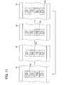
- step S610 the routine returns to step S602 where the selectively indicated range is changed over again to wait for the input of the shift instruction signal from the shift-up switch 16U. Therefore, the indication of the shift range desired by the passenger to be instructed changes over in order as shown in Fig. 11 until it is indicated by the indicator 32a. Therefore, the shift range can be instructed for all of the ranges P, R, N and D.
- the switch instruction signal representing the off-instruction for the engine 5 is input while waiting for the input of the signal from the shift-up switch 16U upon returning to step S602
- the actual range is changed over to the P-range in correspondence to step S115, and the fail-safe control is forcibly terminated.
- the transmission can be changed over to all of the shift ranges P, R, N and D by using the range shifter 16 and the meter part 32 guaranteeing a sufficient degree of fail-safe countermeasure at a low cost.
- the range control circuit 28 for executing steps S101, S102, S108 and S601 to S609 corresponds to indication change-over means
- the range control circuit 28 for executing steps S101, S102, S104 to S107, S115, S610 and S611 correspond to substitute processing means.
- a seventh embodiment is a modification of the first embodiment.
- a navigation device 700 is added.
- the navigation device 700 provides additional functions for operating the vehicle and is used being installed in front of the driver's seat in the vehicle to offer a travel-assisting function.
- the navigation device 700 includes a position detector part 702, a database part 703, a monitor part 704, a speaker part 705 and a navigation control circuit 708.
- the position detector part 702 is constructed by, for example, a receiver, a terrestrial magnetism sensor, a gyro sensor and the like sensors, and detects the present position of the vehicle based on position data signals received from GPS satellites or beacons such as of the DSRC type.
- the database part 703 readably stores in a predetermined storage medium the data, such as map data, character data, voice guidance data, etc. as travel-assisting data for assisting the driving of the vehicle.
- the monitor part 704 displays map data and character data among the travel-assisting data.
- the monitor part 704 of this embodiment is a touch panel type liquid crystal display (LCD) that can be operated upon touching the screen for instructing the operation of the navigation device 700, and outputs a navigation instruction signal representing the content instructed by tough operation to the navigation control circuit 708.
- the speaker part 705 acoustically outputs voice guidance information into the vehicle out of the travel-assisting information.
- the navigation control circuit 708 is an electronic circuit including a microcomputer, and is directly connected to the parts 702 to 705 of the navigation device 700 to be communicable therewith and is, further, connected to the range control circuit 28 through the in-vehicle LAN 6 to be communicable therewith.
- the navigation control circuit 708 receives a detection signal representing the present position from the position detector part 702, reads, from the database part 703, the travel-assisting data best suited for driving the vehicle with the present position as a base point, and offers the data that are read out through the monitor part 704 and the speaker part 705.
- the travel-assisting data are read out and offered according to the navigation instruction signal input through the monitor part 704.
- the navigation control circuit 708 controls the operations of the parts 702 to 705 of the navigation device 700.
- step S102 is executed to invalidate the range instruction signal that has become abnormal and, therefore, the routine proceeds to step S701.
- the control signal is input to the navigation control circuit 708 to control the monitor part 704 and the speaker part 705, and the alarm is generated so that the abnormal range instruction signal is alarmed to the driver.
- step S701 the display on the monitor part 704 is changed from the display of travel-assisting navigation data shown in Fig. 14A over to the display of alarming abnormal condition as shown in Fig. 14B .
- the abnormal condition is displayed and, besides, displays a display change-over button 710 as shown in Fig. 14B for confirming the abnormal condition upon the touch operation and for changing over the display on the screen.
- step S701 alarms the abnormal condition by producing a voice from the speaker part 705 and requests the display change-over button 710 to be touch-operated.
- step S701 may effect neither alarming the abnormal condition by the speaker part 705 nor requesting the operation of the display change-over button 710.
- the abnormal condition may be simply alarmed by outputting a buzzer sound or a tune from the speaker part 705.
- the indicator 32a may be flashed to alarm the abnormal condition as described in the first embodiment or may be simply maintained illuminated.
- step S702 it is checked at step S702 whether the navigation instruction signal responsive to the touch-operation of the display change-over button 710 is input from the monitor part 704 through the navigation control circuit 708. That is, at step S702, it is checked whether the navigation instruction signal representing the operation of the display change-over button 710 responsive to the alarming of abnormal condition at step S701, is input from the monitor part 704. As a result, so far as the determination is negative, step S702 is executed repetitively and the request for operating the display change-over button 710 continues. If the determination is affirmative, the routine proceeds to step S703.
- step S702 In case the switch instruction signal representing the off-instruction for the engine 5 is input while the request is continuing for operating the display change-over button 710 due to the repetition of step S702, the actual range is changed over to the P-range in correspondence to step S115, and the fail-safe control is forcibly terminated.
- the control signal is input to the navigation control circuit 708 to control the monitor part 704 and the speaker part 705 to guide the driver how to operate or handle the vehicle at the time of abnormal condition.
- the display on the monitor part 704 is changed over to a display that guides how to operate the monitor part 704 to instruct the shift ranges as shown in Fig. 14C .
- the embodiment displays how to operate and, further, displays a display change-over button 712 as shown in Fig. 14C for changing over the display on the screen while confirming the method of operation upon receipt of touch-operation.
- step S703 guides the operation method on the monitor part 704 by voice output from the speaker part 705, and requests to touch the display change-over button 712.
- step S703 may effect only one of guiding the operation method by the speaker part 705 and requesting the operation of the display change-over button 712.
- step S704 it is checked at step S704 whether the navigation instruction signal responsive to the touch-operation of the display change-over button 712 is input from the monitor part 704 through the navigation control circuit 708. That is, at step S704, it is checked whether the navigation instruction signal representing the operation of the display change-over button 712 responsive to the guidance of the operation method at step S703, is input from the monitor part 704. As a result, so far as the determination is negative, step S704 is executed repetitively and the request for operating the display change-over button 712 continues. If the determination is affirmative, the routine proceeds to step S104.
- step S704 In case the switch instruction signal representing the off-instruction for the engine 5 is input while the request is continuing for operating the display change-over button 712 due to the repetition of step S704, the actual range is changed over to the P-range in correspondence to step S115, and the fail-safe control is forcibly terminated.
- step S705 the control signal is input to the navigation control circuit 708 to control the monitor part 704, and the display on the monitor part 704 is changed over as shown in Fig. 14D . That is, at step S705 as shown in Fig. 14D , the monitor part 704 displays range selector buttons 714P, 714R, 714N and 714D corresponding to the shift ranges P, R, N and D, as well as a return button 716 for confirming the instruction to return to displaying the travel-assisting data upon receipt of touch-operation. In addition to these displays, step S705 may, further, offer voice guidance for selecting any one of the range selector buttons 714P, 714R, 714N and 714D upon controlling the speaker part 705.
- step S706 it is checked at step S706 whether the navigation instruction signal responsive to the touch-operation of any one of the range selector buttons 714P, 714R, 714N and 174D is input from the monitor part 704 through the navigation control circuit 708. That is, at step S706, it is checked whether the navigation instruction signal representing the range selected from the shift ranges P, R,N and D by operating the monitor part 704 is input from the monitor part 704.
- step S706 the routine proceeds to step S707.
- the navigation instruction signal input from the monitor part 704 is used, instead, as the range instruction signal for instructing the range that is to be selected. Therefore, the shift actuator 26 is so controlled that the actual range represented by the input signal from the rotational position sensor 29 comes in agreement with the selected range and, accordingly, the actual range is changed over to the selected range.
- the control signal is input to the meter control circuit 38 accompanying the change-over of the actual range to control the meter part 32, and the actual range after changed over is indicated by the indicator 32a.
- step S708 the vehicle speed represented by the detection signal input from the vehicle speed sensor 3 is monitored to check whether the vehicle speed SPD is higher than the preset threshold value Sth.
- the preset threshold value of the vehicle speed that serves as a reference for determination may be the same as that of the case of step S105. If the determination is affirmative, therefore, the routine proceeds to step S709 presuming that the vehicle is in a traveling state where the probability of changing over the range is low.
- step S709 the control signal is input to the navigation control circuit 708 to control the monitor part 704, and the display on the monitor part 704 is returned to the display of travel-assisting data.
- the display of travel-assisting data at step S709 adds the display change-over button 712 that corresponds to step S703 as shown in Fig. 14E .
- the routine returns to step S704 to wait for the operation of the display change-over button 712.
- step S710 it is checked whether the navigation instruction signal responsive to the touch-operation of the return button 716 is input from the monitor part 704 through the navigation control circuit 708. That is, it is checked whether the navigation instruction signal for instructing the return to the display of travel-assisting data is input from the monitor part 704.
- step S710 If the determination is affirmative at step S710, the routine proceeds to step S709 assuming that the passenger is hoping to return the display to the display of travel-assisting data. Namely, the display on the monitor part 704 is returned to the display of travel-assisting data, and the routine returns to step S704.
- step S710 If the determination is negative at step S710, on the other hand, the routine returns to step S104 while letting the buttons 714P, 714R, 714N and 714D displayed on the monitor part 704 assuming that the driver is not hoping to return the display to the display of travel-assisting data.
- the navigation device 700 in case the range instruction signal becomes abnormal, the navigation device 700 is used instead to instruct all of the shift ranges P, R, N and D.
- the navigation device 700 instructs the range
- the displayed content of travel-assisting data on the monitor part 704 loses the function for instruction.
- driving the vehicle is not substantially affected.
- the embodiment permits the automatic transmission 2 to be either automatically shifted or manually shifted.
- the monitor part 704 that is operated for instructing the ranges employs the touch panel and is installed in front of the driver's seat for easy operation because of its function for instructing the displayed content of travel-assisting data. Even in case an abnormal condition has occurred, therefore, the shift range can be freely and properly changed over by operating the monitor part 704, and the driving of the vehicle can be continued like when in normal condition featuring high fail-safe performance and cost performance.
- the monitor part 704 further, it is allowed to instruct the range by the monitor part 704 only after the passenger has determined the abnormal condition in response to the alarm. Until the range is instructed, the monitor part 704 guides the method of operation. This offers the effect for suppressing erroneous operation on the monitor part 704 to maintain safety of the vehicle.
- the traveling state may be assumed where the vehicle speed is higher than the preset threshold value, and the display of buttons is returned to displaying the travel-assisting data. Even when the display return button 716 is selected together with the range selector button 714P, 714R, 714N or 714D, similarly, the display is returned to displaying the travel-assisting data.
- the travel-assisting function inherent in the navigation device 700 is resumed when the vehicle is traveling in a state of small probability of changing over the range or when the passenger hopes to display the travel-assisting data again, minimizing the effect upon the travel-assisting function.
- the navigation device 700 corresponds to a travel-assisting device
- the monitor part 704 of the touch panel type corresponds to a second operation part
- the navigation instruction signal output from the monitor part 704 corresponds to a second instruction signal.
- the range control circuit 28 that executes steps S101, S102, S705 and S708 to S710 corresponds to display control means
- the range control circuit 28 that executes steps S101, S102, S104 to S107, S115, S701, S702, S706 and S707 corresponds to substitute processing means.
- the vehicle speed sensor 3 and the range control circuit 28 that executes steps S105 and S708 correspond to speed monitoring means
- the navigation device 700 and the range control circuit 28 that executes steps S101 and S701 correspond to alarm means
- the navigation device 700 and the range control circuit 28 that executes steps S101, S703 and S704 correspond to guide means.
- the range control circuit 28, shift actuator 26, motion conversion mechanism 27, navigation device 700, pedals 7a and 9a, and sensors 3, 7 and 9 correspond to a by-wire control part.
- the shift instruction signal of up-instruction may be used instead of the range instruction signal for instructing the R-range at step S110 and the shift instruction of down-instruction may be used instead of the range instruction signal for instructing the D-range at step S112.
- the response to alarm of the abnormal condition may be determined by inputting a predetermined signal such as a shift instruction signal in correspondence to step S702 of the seventh embodiment after having executed step S103 but before executing step S104.
- a predetermined signal such as a shift instruction signal
- the method of operating the vehicle at the time of abnormal condition may be guided by the meter device 30 or the like equipped with the meter part 32 of the digital meter type, such as a liquid crystal monitor, in correspondence to step S703 of the seventh embodiment after having executed step S103 but before executing step S104.
- steps S301 and S302 may be executed in correspondence to the third embodiment after having executed step S103 but before executing step S104.
- the navigation instruction signal may be determined to be normal or not in correspondence to steps S701 and S702 of the third embodiment after having executed step S702 but before executing step S703. In case the determination is rendered to be abnormal, an abnormal condition may be alarmed to prohibit the change-over of the shift range.
- the third to seventh embodiments may employ the range selector 22 and steps S101 and S102 of the fail-safe control in correspondence to the second embodiment.
- the brake instruction signal may be monitored and may be determined to be normal or not instead of, or in addition to, monitoring the shift instruction signal and determining it to be normal or not.
- the navigation instruction signal input from the monitor part 704 may be determined to be normal or not after having executed step S701 in correspondence to the third embodiment, and the routine may be shifted to step S702 only if the navigation instruction signal is determined to be normal.
- alternate inputs may be determined in correspondence to step S501 of the fifth embodiment instead of, or in addition to, determining the shift instruction signals of up-instruction and down-instruction simultaneously input from the shift switches 16U and 16D.
- input of a shift instruction signal from the shift-up switch 16U may be determined at step S601
- input of a shift instruction signal from the shift-down switch 16D may be determined at step S610
- a shift instruction signal input from the shift-down switch 16D may be used, instead, as the range instruction signal at step S611.
- a device for displaying, for example, an image outside of the vehicle on the monitor part to assist the reverse parking or the traveling at night may be employed as the travel-assisting device.
- a device using, for example, at least one switch provided outside the screen of the monitor part and a remote operation device as the second operation part may be employed as the travel-assisting device.
- the display change-over button 710 may not be displayed at step S701, and step S702 may not be executed to omit the confirmation of abnormal condition.
- step S703 nor step S704 may be executed to omit the explanation of the method of operation and the confirmation of the method of operation.
- step S708 and subsequent step S709 may not be executed to omit the return of the display in case the vehicle speed has exceeded the preset threshold value.
- the return button 716 may not be displayed at step S705, and step S710 and subsequent step S709 may not be executed to omit the return of display that follows the instruction.
Landscapes
- Engineering & Computer Science (AREA)
- General Engineering & Computer Science (AREA)
- Mechanical Engineering (AREA)
- Control Of Transmission Device (AREA)
- Arrangement Or Mounting Of Control Devices For Change-Speed Gearing (AREA)
Applications Claiming Priority (1)
| Application Number | Priority Date | Filing Date | Title |
|---|---|---|---|
| JP2007335907A JP4483943B2 (ja) | 2007-12-27 | 2007-12-27 | 車両制御システム |
Publications (3)
| Publication Number | Publication Date |
|---|---|
| EP2075490A2 true EP2075490A2 (de) | 2009-07-01 |
| EP2075490A3 EP2075490A3 (de) | 2011-03-23 |
| EP2075490B1 EP2075490B1 (de) | 2017-06-07 |
Family
ID=40456487
Family Applications (1)
| Application Number | Title | Priority Date | Filing Date |
|---|---|---|---|
| EP08020259.1A Ceased EP2075490B1 (de) | 2007-12-27 | 2008-11-20 | Fahrzeugsteuerungssystem |
Country Status (3)
| Country | Link |
|---|---|
| US (1) | US8386141B2 (de) |
| EP (1) | EP2075490B1 (de) |
| JP (1) | JP4483943B2 (de) |
Cited By (5)
| Publication number | Priority date | Publication date | Assignee | Title |
|---|---|---|---|---|
| CN103047401A (zh) * | 2012-12-18 | 2013-04-17 | 天津清源电动车辆有限责任公司 | 一种用于电动汽车的电子换挡装置 |
| CN103523020B (zh) * | 2012-07-02 | 2015-10-28 | 福特全球技术公司 | 混合动力车辆及关联的控制方法 |
| US9481351B2 (en) | 2012-07-02 | 2016-11-01 | Ford Global Technologies, Llc | Hybrid vehicle and associated engine start and stop control method |
| DE102011108951B4 (de) * | 2011-07-29 | 2017-08-24 | Audi Ag | Verfahren zur Bedienung eines Shift-by-Wire-Automatikgetriebes |
| WO2017129301A3 (en) * | 2016-01-05 | 2017-09-08 | Zf Friedrichshafen Ag | Operating device for a shift by wire assembly |
Families Citing this family (26)
| Publication number | Priority date | Publication date | Assignee | Title |
|---|---|---|---|---|
| JP4630355B2 (ja) * | 2008-06-19 | 2011-02-09 | ジヤトコ株式会社 | 自動変速機の変速制御装置 |
| JP5515446B2 (ja) * | 2009-06-19 | 2014-06-11 | トヨタ自動車株式会社 | 車両用制御装置および車両用制御方法 |
| US8725368B2 (en) * | 2010-10-13 | 2014-05-13 | GM Global Technology Operations LLC | Rocking enabled shift-by-wire system |
| US8972130B2 (en) * | 2011-02-14 | 2015-03-03 | Toyota Jidosha Kabushiki Kaisha | Control device for vehicle |
| WO2012133808A1 (ja) * | 2011-03-31 | 2012-10-04 | アイシン・エィ・ダブリュ株式会社 | 変速装置の制御装置および制御方法 |
| KR101349404B1 (ko) | 2011-11-28 | 2014-01-15 | 현대자동차주식회사 | 자동변속기의 변속레버용 시프트/틸트 록킹 장치 및 방법 |
| KR20130063159A (ko) * | 2011-12-06 | 2013-06-14 | 현대자동차주식회사 | 시프트 바이 와이어용 자동변속장치 |
| KR20130128988A (ko) * | 2012-05-18 | 2013-11-27 | 현대모비스 주식회사 | 주차 차량의 이동 제어장치 및 그 방법 |
| US8998770B2 (en) | 2012-07-02 | 2015-04-07 | Ford Global Technologies, Llc | Hybrid vehicle and associated engine speed control method |
| DE102013109333A1 (de) * | 2013-08-28 | 2015-03-05 | Dr. Ing. H.C. F. Porsche Aktiengesellschaft | Betätigungsvorrichtung |
| US9169923B2 (en) | 2013-09-05 | 2015-10-27 | Honda Motor Co., Ltd. | Methods and systems for shifting a transmission gear |
| KR101565027B1 (ko) * | 2013-12-13 | 2015-11-02 | 현대자동차주식회사 | 2버튼으로 구성된 통합형 컨트롤러를 이용한 시프트 바이 와이어 오토레버 제어 구조 |
| US9381807B2 (en) * | 2014-05-12 | 2016-07-05 | Fca Us Llc | Electronic shifter limp-home techniques |
| US10054225B2 (en) * | 2015-04-30 | 2018-08-21 | Cnh Industrial America Llc | Self-propelled off-road agricultural vehicle with a dynamically reconfiguring speed control and display system |
| US11371606B2 (en) * | 2016-09-15 | 2022-06-28 | Kongsberg Automotive Ab | Arrangement for reading off predetermined positions of a gear lever in a gear selector in a vehicle |
| KR20200007039A (ko) * | 2017-06-28 | 2020-01-21 | 쟈트코 가부시키가이샤 | 시프터의 이상 진단 장치 및 시프터의 이상 진단 방법 |
| JP2019070394A (ja) * | 2017-10-06 | 2019-05-09 | スズキ株式会社 | 車両の制御装置 |
| JP7069735B2 (ja) | 2018-01-15 | 2022-05-18 | トヨタ自動車株式会社 | 自動車 |
| JP6950545B2 (ja) * | 2018-01-19 | 2021-10-13 | 株式会社デンソー | シフトレンジ制御装置 |
| JP7070441B2 (ja) * | 2019-01-11 | 2022-05-18 | 株式会社デンソー | シフトバイワイヤ制御装置 |
| JP2022034482A (ja) * | 2020-08-18 | 2022-03-03 | 株式会社東海理化電機製作所 | シフト装置 |
| JP2022073446A (ja) * | 2020-11-02 | 2022-05-17 | 株式会社デンソー | センサ装置 |
| CN112594371A (zh) * | 2020-12-15 | 2021-04-02 | 大运汽车股份有限公司 | 对机动车的换挡控制方法、装置、终端及介质 |
| CN114087355B (zh) * | 2021-01-26 | 2022-10-25 | 长城汽车股份有限公司 | 车辆档位切换方法、装置以及车辆 |
| US12560077B2 (en) * | 2021-06-15 | 2026-02-24 | Intelligent Wellhead Systems Inc. | Apparatus, system, and method for indicating a position of an actuator of wellsite equipment |
| CN114439915A (zh) * | 2021-11-18 | 2022-05-06 | 广西宁达汽车科技有限公司 | 一种换挡系统、方法、存储介质和电动汽车 |
Citations (2)
| Publication number | Priority date | Publication date | Assignee | Title |
|---|---|---|---|---|
| EP1146257A2 (de) | 2000-04-14 | 2001-10-17 | Siemens Aktiengesellschaft | Vorrichtung zur Auswahl einer Fahrstufe oder Gangstufe eines Kraftfahrzeuggetriebes |
| DE102006010909A1 (de) | 2006-03-09 | 2007-09-13 | Audi Ag | Kraftfahrzeug |
Family Cites Families (15)
| Publication number | Priority date | Publication date | Assignee | Title |
|---|---|---|---|---|
| JPH0543904A (ja) | 1991-07-16 | 1993-02-23 | Inter Metallics Kk | 永久磁石圧粉体の製造方法 |
| JPH05203042A (ja) | 1992-01-24 | 1993-08-10 | Toyota Motor Corp | 自動変速機用レンジ切換弁の制御装置 |
| JP3451378B2 (ja) | 1993-08-09 | 2003-09-29 | 本田技研工業株式会社 | オートマチック車の変速ギア制御装置 |
| JP3746343B2 (ja) | 1996-12-19 | 2006-02-15 | トヨタ自動車株式会社 | 自動変速機制御装置 |
| JP4543444B2 (ja) | 1999-02-24 | 2010-09-15 | 株式会社エクォス・リサーチ | 車両制御装置 |
| JP3582431B2 (ja) | 1999-11-25 | 2004-10-27 | 日産自動車株式会社 | 自動変速機の選択レンジ切り換え制御装置 |
| DE19957151B4 (de) * | 1999-11-27 | 2006-06-01 | Daimlerchrysler Ag | Schaltvorrichtung |
| IT1320577B1 (it) * | 2000-08-01 | 2003-12-10 | Magneti Marelli Spa | Dispositivo selettore di marce per cambio automatizzato. |
| JP2002139143A (ja) * | 2000-11-06 | 2002-05-17 | Tokai Rika Co Ltd | 車両用変速機制御装置 |
| US6848332B2 (en) * | 2001-03-01 | 2005-02-01 | Kabushiki Kaisha Tokai Rika Denki Seisakusho | Shift device and switch device thereof for vehicle |
| DE10222665A1 (de) * | 2002-05-22 | 2003-12-11 | Bosch Gmbh Robert | Verfahren zur Konfiguration einer Getriebesteuerung für Kraftfahrzeuge |
| JP3873890B2 (ja) | 2003-01-20 | 2007-01-31 | トヨタ自動車株式会社 | 車両用自動変速機の制御装置 |
| JP2004353827A (ja) | 2003-05-30 | 2004-12-16 | Suzuki Motor Corp | 車両用自動変速機のシフト装置 |
| JP4624857B2 (ja) | 2005-05-31 | 2011-02-02 | 株式会社デンソー | 車両制御システム |
| US7640104B2 (en) * | 2006-02-27 | 2009-12-29 | Xanavi Informatics Corporation | Vehicle navigation system and method for displaying waypoint information |
-
2007
- 2007-12-27 JP JP2007335907A patent/JP4483943B2/ja not_active Expired - Fee Related
-
2008
- 2008-11-20 EP EP08020259.1A patent/EP2075490B1/de not_active Ceased
- 2008-12-23 US US12/342,290 patent/US8386141B2/en not_active Expired - Fee Related
Patent Citations (2)
| Publication number | Priority date | Publication date | Assignee | Title |
|---|---|---|---|---|
| EP1146257A2 (de) | 2000-04-14 | 2001-10-17 | Siemens Aktiengesellschaft | Vorrichtung zur Auswahl einer Fahrstufe oder Gangstufe eines Kraftfahrzeuggetriebes |
| DE102006010909A1 (de) | 2006-03-09 | 2007-09-13 | Audi Ag | Kraftfahrzeug |
Cited By (6)
| Publication number | Priority date | Publication date | Assignee | Title |
|---|---|---|---|---|
| DE102011108951B4 (de) * | 2011-07-29 | 2017-08-24 | Audi Ag | Verfahren zur Bedienung eines Shift-by-Wire-Automatikgetriebes |
| CN103523020B (zh) * | 2012-07-02 | 2015-10-28 | 福特全球技术公司 | 混合动力车辆及关联的控制方法 |
| US9409566B2 (en) | 2012-07-02 | 2016-08-09 | Ford Global Technologies, Llc | Hybrid vehicle and associated control method |
| US9481351B2 (en) | 2012-07-02 | 2016-11-01 | Ford Global Technologies, Llc | Hybrid vehicle and associated engine start and stop control method |
| CN103047401A (zh) * | 2012-12-18 | 2013-04-17 | 天津清源电动车辆有限责任公司 | 一种用于电动汽车的电子换挡装置 |
| WO2017129301A3 (en) * | 2016-01-05 | 2017-09-08 | Zf Friedrichshafen Ag | Operating device for a shift by wire assembly |
Also Published As
| Publication number | Publication date |
|---|---|
| EP2075490B1 (de) | 2017-06-07 |
| US20090171544A1 (en) | 2009-07-02 |
| EP2075490A3 (de) | 2011-03-23 |
| JP2009154738A (ja) | 2009-07-16 |
| JP4483943B2 (ja) | 2010-06-16 |
| US8386141B2 (en) | 2013-02-26 |
Similar Documents
| Publication | Publication Date | Title |
|---|---|---|
| EP2075490B1 (de) | Fahrzeugsteuerungssystem | |
| US6699155B2 (en) | Vehicle transmission controller | |
| US4598374A (en) | Gearshift selection system for a power-assisted transmission | |
| US10920878B2 (en) | Shift-by-wire selector control system for a motor vehicle transmission and method therefor | |
| EP1180618B1 (de) | Kraftfahrzeugschalthebel für ein Automatik-Getriebe | |
| US20020166399A1 (en) | Apparatus for controlling vehicle transmission | |
| GB2228980A (en) | Gearshift control with automatic control of clutch | |
| EP2112408B1 (de) | Shift-by-Wire-Schaltanordnung | |
| EP1610037B1 (de) | Automatische drehzahländerungssteuervorrichtung | |
| EP1628047B1 (de) | Wähleinrichtung für ein Kraftfahrzeuggetriebe | |
| JP4397045B2 (ja) | 車両制御システム | |
| JP2001301483A (ja) | シフトレバー装置及び移動体位置検出装置 | |
| JP5234309B2 (ja) | 変速制御装置 | |
| JP4953088B2 (ja) | 自動変速機のシフト操作装置 | |
| JP2007224949A (ja) | 自動変速機の制御装置 | |
| KR20180061465A (ko) | Sbw 시스템의 변속제어 오류 진단 장치 및 방법 | |
| JP2558501Y2 (ja) | オートチェンジ | |
| JPH0718064U (ja) | 電動オートチェンジ | |
| KR100217101B1 (ko) | 자동 변속기 차량의 엔진 브레이킹 시스템 및 그 제어 방법 | |
| KR20010039249A (ko) | 보조 변속 시스템 | |
| KR19980045491A (ko) | 변속 쇼크 방지장치 | |
| KR19980060167A (ko) | 자동 변속기 오일량 자동 점검 시스템 | |
| KR19980045003U (ko) | 자동차용 자동변속기 제어시스템 |
Legal Events
| Date | Code | Title | Description |
|---|---|---|---|
| PUAI | Public reference made under article 153(3) epc to a published international application that has entered the european phase |
Free format text: ORIGINAL CODE: 0009012 |
|
| AK | Designated contracting states |
Kind code of ref document: A2 Designated state(s): AT BE BG CH CY CZ DE DK EE ES FI FR GB GR HR HU IE IS IT LI LT LU LV MC MT NL NO PL PT RO SE SI SK TR |
|
| AX | Request for extension of the european patent |
Extension state: AL BA MK RS |
|
| PUAL | Search report despatched |
Free format text: ORIGINAL CODE: 0009013 |
|
| AK | Designated contracting states |
Kind code of ref document: A3 Designated state(s): AT BE BG CH CY CZ DE DK EE ES FI FR GB GR HR HU IE IS IT LI LT LU LV MC MT NL NO PL PT RO SE SI SK TR |
|
| AX | Request for extension of the european patent |
Extension state: AL BA MK RS |
|
| RIC1 | Information provided on ipc code assigned before grant |
Ipc: F16H 61/32 20060101ALI20110216BHEP Ipc: F16H 61/12 20100101AFI20090327BHEP Ipc: F16H 59/12 20060101ALI20110216BHEP Ipc: F16H 59/02 20060101ALI20110216BHEP |
|
| 17P | Request for examination filed |
Effective date: 20110921 |
|
| AKX | Designation fees paid |
Designated state(s): DE FR |
|
| 17Q | First examination report despatched |
Effective date: 20120503 |
|
| GRAP | Despatch of communication of intention to grant a patent |
Free format text: ORIGINAL CODE: EPIDOSNIGR1 |
|
| STAA | Information on the status of an ep patent application or granted ep patent |
Free format text: STATUS: GRANT OF PATENT IS INTENDED |
|
| INTG | Intention to grant announced |
Effective date: 20161222 |
|
| GRAS | Grant fee paid |
Free format text: ORIGINAL CODE: EPIDOSNIGR3 |
|
| GRAA | (expected) grant |
Free format text: ORIGINAL CODE: 0009210 |
|
| STAA | Information on the status of an ep patent application or granted ep patent |
Free format text: STATUS: THE PATENT HAS BEEN GRANTED |
|
| AK | Designated contracting states |
Kind code of ref document: B1 Designated state(s): DE FR |
|
| GRAA | (expected) grant |
Free format text: ORIGINAL CODE: 0009210 |
|
| REG | Reference to a national code |
Ref country code: DE Ref legal event code: R096 Ref document number: 602008050546 Country of ref document: DE |
|
| REG | Reference to a national code |
Ref country code: DE Ref legal event code: R084 Ref document number: 602008050546 Country of ref document: DE |
|
| REG | Reference to a national code |
Ref country code: FR Ref legal event code: PLFP Year of fee payment: 10 |
|
| REG | Reference to a national code |
Ref country code: DE Ref legal event code: R097 Ref document number: 602008050546 Country of ref document: DE |
|
| PLBE | No opposition filed within time limit |
Free format text: ORIGINAL CODE: 0009261 |
|
| STAA | Information on the status of an ep patent application or granted ep patent |
Free format text: STATUS: NO OPPOSITION FILED WITHIN TIME LIMIT |
|
| 26N | No opposition filed |
Effective date: 20180308 |
|
| PGFP | Annual fee paid to national office [announced via postgrant information from national office to epo] |
Ref country code: FR Payment date: 20181123 Year of fee payment: 11 |
|
| PG25 | Lapsed in a contracting state [announced via postgrant information from national office to epo] |
Ref country code: FR Free format text: LAPSE BECAUSE OF NON-PAYMENT OF DUE FEES Effective date: 20191130 |
|
| PGFP | Annual fee paid to national office [announced via postgrant information from national office to epo] |
Ref country code: DE Payment date: 20221123 Year of fee payment: 15 |
|
| REG | Reference to a national code |
Ref country code: DE Ref legal event code: R119 Ref document number: 602008050546 Country of ref document: DE |
|
| PG25 | Lapsed in a contracting state [announced via postgrant information from national office to epo] |
Ref country code: DE Free format text: LAPSE BECAUSE OF NON-PAYMENT OF DUE FEES Effective date: 20240601 |
|
| PG25 | Lapsed in a contracting state [announced via postgrant information from national office to epo] |
Ref country code: DE Free format text: LAPSE BECAUSE OF NON-PAYMENT OF DUE FEES Effective date: 20240601 |