EP2075975A1 - Serveur relais et système de communication à relais - Google Patents
Serveur relais et système de communication à relais Download PDFInfo
- Publication number
- EP2075975A1 EP2075975A1 EP08019680A EP08019680A EP2075975A1 EP 2075975 A1 EP2075975 A1 EP 2075975A1 EP 08019680 A EP08019680 A EP 08019680A EP 08019680 A EP08019680 A EP 08019680A EP 2075975 A1 EP2075975 A1 EP 2075975A1
- Authority
- EP
- European Patent Office
- Prior art keywords
- resource
- information
- relay
- relay server
- resource information
- Prior art date
- Legal status (The legal status is an assumption and is not a legal conclusion. Google has not performed a legal analysis and makes no representation as to the accuracy of the status listed.)
- Granted
Links
Images




Classifications
-
- H—ELECTRICITY
- H04—ELECTRIC COMMUNICATION TECHNIQUE
- H04L—TRANSMISSION OF DIGITAL INFORMATION, e.g. TELEGRAPHIC COMMUNICATION
- H04L67/00—Network arrangements or protocols for supporting network services or applications
- H04L67/01—Protocols
- H04L67/10—Protocols in which an application is distributed across nodes in the network
- H04L67/104—Peer-to-peer [P2P] networks
-
- H—ELECTRICITY
- H04—ELECTRIC COMMUNICATION TECHNIQUE
- H04L—TRANSMISSION OF DIGITAL INFORMATION, e.g. TELEGRAPHIC COMMUNICATION
- H04L67/00—Network arrangements or protocols for supporting network services or applications
- H04L67/01—Protocols
- H04L67/10—Protocols in which an application is distributed across nodes in the network
- H04L67/104—Peer-to-peer [P2P] networks
- H04L67/1059—Inter-group management mechanisms, e.g. splitting, merging or interconnection of groups
-
- H—ELECTRICITY
- H04—ELECTRIC COMMUNICATION TECHNIQUE
- H04L—TRANSMISSION OF DIGITAL INFORMATION, e.g. TELEGRAPHIC COMMUNICATION
- H04L67/00—Network arrangements or protocols for supporting network services or applications
- H04L67/01—Protocols
- H04L67/10—Protocols in which an application is distributed across nodes in the network
- H04L67/104—Peer-to-peer [P2P] networks
- H04L67/1061—Peer-to-peer [P2P] networks using node-based peer discovery mechanisms
- H04L67/1065—Discovery involving distributed pre-established resource-based relationships among peers, e.g. based on distributed hash tables [DHT]
-
- H—ELECTRICITY
- H04—ELECTRIC COMMUNICATION TECHNIQUE
- H04L—TRANSMISSION OF DIGITAL INFORMATION, e.g. TELEGRAPHIC COMMUNICATION
- H04L67/00—Network arrangements or protocols for supporting network services or applications
- H04L67/50—Network services
- H04L67/56—Provisioning of proxy services
-
- G—PHYSICS
- G06—COMPUTING OR CALCULATING; COUNTING
- G06F—ELECTRIC DIGITAL DATA PROCESSING
- G06F16/00—Information retrieval; Database structures therefor; File system structures therefor
- G06F16/10—File systems; File servers
- G06F16/18—File system types
- G06F16/182—Distributed file systems
-
- H—ELECTRICITY
- H04—ELECTRIC COMMUNICATION TECHNIQUE
- H04L—TRANSMISSION OF DIGITAL INFORMATION, e.g. TELEGRAPHIC COMMUNICATION
- H04L12/00—Data switching networks
- H04L12/66—Arrangements for connecting between networks having differing types of switching systems, e.g. gateways
-
- H—ELECTRICITY
- H04—ELECTRIC COMMUNICATION TECHNIQUE
- H04L—TRANSMISSION OF DIGITAL INFORMATION, e.g. TELEGRAPHIC COMMUNICATION
- H04L41/00—Arrangements for maintenance, administration or management of data switching networks, e.g. of packet switching networks
- H04L41/08—Configuration management of networks or network elements
- H04L41/0894—Policy-based network configuration management
-
- H—ELECTRICITY
- H04—ELECTRIC COMMUNICATION TECHNIQUE
- H04L—TRANSMISSION OF DIGITAL INFORMATION, e.g. TELEGRAPHIC COMMUNICATION
- H04L67/00—Network arrangements or protocols for supporting network services or applications
- H04L67/01—Protocols
- H04L67/10—Protocols in which an application is distributed across nodes in the network
- H04L67/104—Peer-to-peer [P2P] networks
- H04L67/1061—Peer-to-peer [P2P] networks using node-based peer discovery mechanisms
- H04L67/1063—Discovery through centralising entities
-
- H—ELECTRICITY
- H04—ELECTRIC COMMUNICATION TECHNIQUE
- H04L—TRANSMISSION OF DIGITAL INFORMATION, e.g. TELEGRAPHIC COMMUNICATION
- H04L67/00—Network arrangements or protocols for supporting network services or applications
- H04L67/01—Protocols
- H04L67/10—Protocols in which an application is distributed across nodes in the network
- H04L67/1095—Replication or mirroring of data, e.g. scheduling or transport for data synchronisation between network nodes
Definitions
- Fig. 9 illustrates the family resource information having the content updated by a synchronization instruction according to a preferred embodiment of the present invention.
- Fig. 10 is a sequence chart illustrating a communication process that creates a relay group according to a preferred embodiment of the present invention.
- Fig. 15 is a flowchart of a process in which a server that has received the synchronization instruction transmits a synchronization command to a sharing member terminal according to a preferred embodiment of the present invention.
- FIG. 1 illustrates an overall configuration of a relay communication system according to a preferred embodiment of the present invention.
- the WAN is a network that connects different LANs to each other,
- the Internet is preferably used as the WAN, for example.
- Fig. 2 is a functional block diagram of the external server 2.
- the external server 2 is a device that facilitates the communication performed between the relay servers 1 each arranged in the respective LANs, and the Internet.
- the external server 2 preferably includes a WAN interface 201, a control unit 202, and a relay server account information database 203 as a primary configuration.
- the control unit 202 is a processing unit that controls various communications performed through the WAN interface 201, and controls communication processes complying with protocols such as Transmission Control Protocol/Internet Protocol (TCP/IP), User Datagram Protocol (UDP) and SIP.
- TCP/IP Transmission Control Protocol/Internet Protocol
- UDP User Datagram Protocol
- SIP Session Initiation Protocol
- the control unit 202 performs, for example, a process of receiving the account of the relay server 1 from each relay server 1 and a process of registering the received account in the relay server account information database 203.
- the control unit 202 performs, for example, a process of relaying communication data, such as various SIP methods and responses transmitted from the relay server 1, to other relay servers 1.
- Fig. 3 is a functional block diagram of the client terminal 5.
- the client terminal 5 is a terminal that can be directly operated by a user, and includes a Personal Computer (PC) or other similar devices used by the user, for example, on a daily basis. Accordingly, a great number of client terminals 5 typically exist in the LAN.
- client terminals 11, 12 are connected to the LAN 91
- client terminals 21, 22 are connected to the LAN 92
- client terminals 31, 32 are connected to the LAN 93
- client terminals 41, 42 are connected to the LAN 94.
- a private IP address uniquely managed in the same LAN is provided for each client terminal 5.
- the client terminal 5 preferably includes a LAN interface 601, a control unit 602, a resource storage unit 603, and a shared resource information database 604 as a primary configuration.
- the LAN interface 601 is an interface arranged to communicate with each apparatus, such as the relay server 1 and the file server 6 connected to the same LAN, by using the private IP address.
- the control unit 602 is a processing unit that controls various communications performed through the LAN interface 601.
- the control unit 602 controls communication processes complying with protocols such as TCP/IP, UDP, and SIP.
- the control unit 602 performs, for example, a process of controlling the handling such as movement (transfer), change, deletion, etc., of the resources stored in the resource storage unit 603.
- the control unit 602 also performs a process of updating the shared resource information stored in the shared resource information database 604 when a change notification of the shared resource information is received from the relay server 1.
- a relay server 1 is arranged in each LAN. Specifically, a relay server R1 is arranged in the LAN 91, a relay server R2 is arranged in the LAN 92, a relay server R3 is arranged in the LAN 93, and a relay server R4 is arranged in the LAN 94.
- the relay server 1 is connected to the LAN, and can communicate with each client terminal 5 that is connected to the same LAN.
- the relay server 1 is also connected to the Internet, and can communicate with the relay servers 1 that are connected to the other LANs (through the external server 2).
- each relay server 1 is provided with both a private IP address and a global IP address.
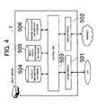
- the LAN interface 501 is an interface arranged to communicate with the client terminal 5 connected to the same LAN (i.e., the LAN to which the relay server 1 is connected), by using the private IP address.
- the relay server R1 can communicate with each of the client terminals 11, 12 in the LAN 91 by using the LAN interface 501.
- the WAN interface 502 is an interface arranged to communicate with each apparatus such as the external server 2 connected to the Internet, by using the global IP address.
- Each relay server 1 includes a function of an SIP registrar server, and communicates with each client terminal 5 by using a SIP.
- the relay server R2 functions as a SIP registrar server, receives an account of each client terminal 21, 22 connected to the LAN 92, and registers the received accounts in the account information database 504.
- the account information database 504 of Fig. 4 is a database that manages, in association with the private IP address, the account of the client terminal 5 that has made a registration request.
- the shared resource information database 506 is preferably a database that manages the shared resource information related to the client terminal 5 registered in the account information database 504.
- the control unit 503 is preferably a processing unit that controls various communications performed through the LAN interface 501 and the WAN interface 502, and controls various communication processes complying with protocols such as TCP/IP, UDP, SIP, etc.
- control unit 503 performs a process of transmitting an account thereof to the external server 2 and requesting registration of the account, and a process of creating the relay group information to store in the relay group information database 505.
- the control unit 503 also performs a process of creating the shared resource information to store in the shared resource information database 506.
- the file server 6 will now be described. As illustrated in Fig. 1 , the file server 6 is connected to the LAN, and can communicate with each client terminal 5 connected to the same LAN.
- the file server 6 can store resources such as files, folders, etc., and functions as a resource storage unit alternative to the resource storage unit 603 (shown in Fig. 3 ) of each client terminal 5.
- the resource that can be handled by each client terminal 5 may be stored in a local disc of the client terminal 5, and/or may be stored in the file server 6 provided as a network drive.
- the file server 6 is not necessarily required in each LAN, and the installation thereof is omitted in the LANs 92 and 94 (shown in Fig.1 ).
- the relay group information and the shared resource information which are information handled in the relay communication system of the present preferred embodiment, will now be described.
- Fig. 6 illustrates an example of content of the relay group information.
- the relay group information 100a and 100b includes group identification information 101, information (relay account information) 102 of the relay server 1 that forms a relay group by enabling connection with one another, and resource sharable terminal information 110.
- the relay account information 102 includes information about the account of each relay server 1 that forms a relay group by enabling the connection with one another.
- the relay group information 100a illustrated on an upper side of Fig. 6 the accounts of the relay servers R1, R2, and R3 that form a relay group are described.
- the relay group information 100b illustrated on a lower side of Fig. 6 the account of the relay server R3 that forms another relay group is described.
- the relay group information 100a and 100b are created such that they can be uniquely identified with respect to each relay group.
- the relay group information 100a and 100b include the account (relay account information 102) of each relay server that forms a group (relay group) by enabling the connection with one another. Accordingly, by referring to the relay group information 100a and 100b, the operator or the user can recognize which LANs form a group.
- the resource sharable terminal information 110 is registered in association with each piece of relay group information 100.
- resource sharable terminal information 110a is registered in association with the relay group information 100a
- resource sharable terminal information 110b is registered in association with the relay group information 100b.
- the relay group information 100a corresponding to the resource sharable terminal information 110a illustrated on the upper side of Fig. 6 defines the relay group that is formed by the relay servers R1, R2, and R3.
- the client terminals 11 and 12 are arranged in the LAN 91 to which the relay server R1 is connected.
- the two client terminals 11 and 12 are selected as the terminals that can share the resource in the relay group, and account information thereof is registered as the individual terminal information 111.
- the client terminals 21 and 22 are selected as the resource sharable terminals in the LAN 92 to which the relay server R2 is connected.
- the client terminals 31 and 32 are arranged in the LAN 93 to which the relay server R3 is connected, in the example of the resource sharable terminal information 110a, only the client terminal 31 is selected as the resource sharable terminal, and account information thereof is registered as the individual terminal information 111.
- the relay group information 100b corresponding to the resource sharable terminal information 110b illustrated on the lower side of Fig. 6 defines the relay group formed by only the relay server R3.
- the two client terminals 31 and 32 are selected as the resource sharable terminals in the LAN 93 to which the relay server R3 is connected, and account information thereof is registered as the individual terminal information 111.
- each individual terminal information 111 is described in association with the relay account information 102 of the relay server connected to the LAN to which the resource sharable terminals are connected.
- the individual terminal information 111 related to the client terminal 11 is described in association with the relay account information 102a of the relay server R1.
- the account identification information 121 is used to identify the created shared resource information 120.
- the shared resource identification information 123 is used to identify the individual shared resource information 122 thereof, and can be uniquely identified by being given a different ID each time the individual shared resource information 122 is created.
- the shared resource identification information 123 includes (1) an ID that is associated with the client terminal 5 that has made a request for creating the shared resource information 120 and (2) a name that is used to identify the ID easily.
- the ID may be "20071001150032client11@relay-server1" or the like, and the name for easily performing the identification may be "workspacel", or the like.
- the family account information 124 of Fig. 7 includes collections of information of accounts (for example, client11@relay-server1.net) of the client terminals 5 that share the resource indicated in the family resource information 125.
- Each sharing member terminal stores, in the shared resource information database 604, the shared resource information 120 including the individual shared resource information 122 having the above-described content.
- the family resource information 125a of Fig. 9 illustrates an example in which a file (i.e., the resource located in "//network/z://folderZ/estimate.xls") that is named "file00ZX.xls" at the time of sharing is updated when the user operates the client terminal 11. More specifically, since the content of the file is updated, a portion (indicating the time stamp and file size information) surrounded by a rectangle of the family resource information 125a is updated from the state of Fig. 8 in response to the synchronization with the file.
- the family resource information 125e of Fig. 9 illustrates an example of a file (i.e., the resource located in "c:/temp/document1.pdf") that is named "file100.pdf" at the time of sharing is deleted when the user operates the client terminal 31.
- sequence numbers 11 through 19 of Fig. 10 generation steps and registration steps of the relay group will be described. Processes of sequence numbers 11 through 19 of Fig. 10 are performed as initial settings of the network by the user and operator.
- the relay server R2 transmits a "request-server-info message" to the relay server R1 (sequence number 13), and the relay server R1 returns information (server-info) related thereto to the relay server R2.
- both the information related to the relay server R1 and the information related to the relay server R2 are described in the relay account information 102 of the relay group information 100, and are stored in the relay group information database 505 of each relay server R1 and R2.
- the relay group information 100 (i.e., information having the content of relay group information 100a of Fig. 6 ) indicating that the relay servers R1, R2, and R3 form the relay group is stored in the relay group information database 505 of each relay server R1, R2, and R3.
- the relay server R1 searches the relay group information database 505 thereof. Then, the relay server R1 adds the individual terminal information 111 of the client terminal 11 to the resource sharable terminal information 110 that corresponds to the relay group information of the specified identification ID.
- the relay server R2 searches the relay group information database 505 thereof, and adds the individual terminal information 111 of the client terminal 21 to the resource sharable terminal information 110 that corresponds to the relay group information specified by using the identification ID.
- the relay server R2 transmits, to the relay server R1, an "add-group-info message" requesting for addition of the resource sharable terminal to the relay group (sequence number 24).
- the message includes an account of the client terminal 21 to be added and the identification ID of the registration destination relay group, or the like.
- the relay server R2 also transmits, to the relay server R3, the "add-group-info message" requesting for addition of the resource sharable terminal to the relay group (sequence number 26). Having received the message, the relay server R3 adds the individual terminal information 111 of the client terminal 21 to the resource sharable terminal information 110 stored in the relay group information database 505, and then returns an "OK" response.
- a method (addTerminal method) in which the identification ID of the relay group is specified and the client terminal 31 is registered as the resource sharable terminal is executed by the operator.
- the individual terminal information 111 of each client terminal 11, 21, 31 as the resource sharable terminal is registered in the resource sharable terminal information 110 of the relay group information 100 stored in the relay group information database 505 of each relay server R1, R2, and R3.
- the relay servers R2 and R3 check the family account information 124 of the shared resource information 120 stored in the respective resource information databases 506. Then, the relay servers R2 and R3 find the client terminals (in the present example, the terminals 21, 22, and 31), which belong to the relay server R2 or R3 and are the user client terminals. Accordingly, the relay servers R2 and R3 transmit the synchronization instruction to the client terminals. These processes correspond to the sequence numbers 41.1.1, 41.1.2, and 41.2.1.
- the synchronization instruction includes information that indicates which shared resource information is to be synchronized.
- the relay group formed by the client terminals 11, 12, 21, 22, and 31 and the relay group formed by the client terminals 31 and 32 are registered (relay group information 100a and 100b of Fig. 6 ).
- the "file100.pdf" which is shared by the former relay group and is detected to be non-existent by the synchronization instruction, is also shared by the client terminals 31 and 32 in the latter relay group.
- the illustration of a specific content of the shared resource information of the relay group formed by the client terminals 31 and 32 is omitted.
- the relay server R1 can distribute a synchronization instruction with respect to a certain resource (such as "folderB") of the shared resource information 120 (sequence numbers 51. 1 and 52, etc.)
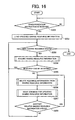
- the client terminal 5 acquires the corresponding shared resource information (S204), and checks whether or not the resource can be accessed (S205). If the resource can be accessed, the terminal 5 returns to the checking of other shared resources. If the resource cannot be accessed, the client terminal 5 performs a process of deleting the corresponding resource information from the shared resource information (S206), and transmits a shared resource information update command to the relay server 1 (S207). Then, the client terminal 5 checks whether or not there is other shared resource information that includes the deleted shared resource (S208).
Landscapes
- Engineering & Computer Science (AREA)
- Computer Networks & Wireless Communication (AREA)
- Signal Processing (AREA)
- Information Transfer Between Computers (AREA)
- Data Exchanges In Wide-Area Networks (AREA)
- Information Retrieval, Db Structures And Fs Structures Therefor (AREA)
- Small-Scale Networks (AREA)
- Computer And Data Communications (AREA)
Applications Claiming Priority (1)
| Application Number | Priority Date | Filing Date | Title |
|---|---|---|---|
| JP2007333156A JP4591875B2 (ja) | 2007-12-25 | 2007-12-25 | 中継サーバ及び中継通信システム |
Publications (2)
| Publication Number | Publication Date |
|---|---|
| EP2075975A1 true EP2075975A1 (fr) | 2009-07-01 |
| EP2075975B1 EP2075975B1 (fr) | 2014-02-19 |
Family
ID=40566316
Family Applications (1)
| Application Number | Title | Priority Date | Filing Date |
|---|---|---|---|
| EP08019680.1A Ceased EP2075975B1 (fr) | 2007-12-25 | 2008-11-11 | Serveur relais et système de communication à relais |
Country Status (4)
| Country | Link |
|---|---|
| US (1) | US8949419B2 (fr) |
| EP (1) | EP2075975B1 (fr) |
| JP (1) | JP4591875B2 (fr) |
| CN (1) | CN101471843B (fr) |
Cited By (1)
| Publication number | Priority date | Publication date | Assignee | Title |
|---|---|---|---|---|
| EP2960803A4 (fr) * | 2013-02-22 | 2016-10-12 | Nec Corp | Système de partage de données |
Families Citing this family (7)
| Publication number | Priority date | Publication date | Assignee | Title |
|---|---|---|---|---|
| EP1990975B1 (fr) * | 2007-05-09 | 2013-02-20 | Murata Machinery, Ltd. | Serveur relais et système de communication à relais |
| JP5636941B2 (ja) * | 2010-12-16 | 2014-12-10 | 村田機械株式会社 | 中継通信システムおよび中継サーバ |
| WO2013171858A1 (fr) * | 2012-05-16 | 2013-11-21 | 株式会社Synclogue | Programme de synchronisation et procédé de synchronisation |
| US10963431B2 (en) * | 2013-06-11 | 2021-03-30 | Red Hat, Inc. | Storing an object in a distributed storage system |
| CN103401896B (zh) * | 2013-07-15 | 2016-06-22 | 四川公用信息产业有限责任公司 | 一种多Android客户端服务共享方法及系统 |
| CN105847366A (zh) * | 2016-03-29 | 2016-08-10 | 乐视控股(北京)有限公司 | 一种共享推送服务的方法和装置 |
| US11177974B2 (en) * | 2020-01-27 | 2021-11-16 | International Business Machines Corporation | Consistent provision of member node group information on virtual overlay network |
Citations (5)
| Publication number | Priority date | Publication date | Assignee | Title |
|---|---|---|---|---|
| US20020143956A1 (en) * | 2001-04-03 | 2002-10-03 | Murata Kikai Kabushiki Kaisha | Relay server |
| US20020143855A1 (en) * | 2001-01-22 | 2002-10-03 | Traversat Bernard A. | Relay peers for extending peer availability in a peer-to-peer networking environment |
| JP2007333156A (ja) | 2006-05-19 | 2007-12-27 | Inoue Sudare Kk | 管継手 |
| EP1940126A2 (fr) * | 2006-12-19 | 2008-07-02 | Murata Machinery Ltd. | Serveur de relais et terminal de client |
| EP1942634A1 (fr) * | 2006-11-24 | 2008-07-09 | Murata Machinery, Ltd. | Serveur relais, système de communication à relais et dispositif de communication |
Family Cites Families (81)
| Publication number | Priority date | Publication date | Assignee | Title |
|---|---|---|---|---|
| JPH04105143A (ja) | 1990-08-24 | 1992-04-07 | Nec Corp | ファイル共有方式 |
| JPH09168055A (ja) | 1995-12-18 | 1997-06-24 | Fujitsu Ltd | セキュリティ制御装置 |
| JPH09282216A (ja) | 1996-04-18 | 1997-10-31 | Kobe Nippon Denki Software Kk | クライアントサーバシステム |
| US7136903B1 (en) * | 1996-11-22 | 2006-11-14 | Mangosoft Intellectual Property, Inc. | Internet-based shared file service with native PC client access and semantics and distributed access control |
| JP2000059465A (ja) | 1998-08-07 | 2000-02-25 | Hitachi Ltd | 障害監視管理方式 |
| JP3415456B2 (ja) | 1998-10-19 | 2003-06-09 | 日本電気株式会社 | ネットワークシステム及びコマンド使用権限制御方法ならびに制御プログラムを格納した記憶媒体 |
| JP2001092702A (ja) | 1999-09-20 | 2001-04-06 | Fujitsu Ltd | 情報処理システム、サーバ装置、クライアント装置、及び記録媒体 |
| JP2001292167A (ja) | 2000-04-10 | 2001-10-19 | Fujitsu Ltd | ネットワーク中継システムおよび中継装置 |
| JP2001306382A (ja) | 2000-04-24 | 2001-11-02 | Hitachi Ltd | 共用ファイルアクセス方法及びその実施装置並びにその処理プログラムを記録した記録媒体 |
| JP2002007182A (ja) | 2000-06-20 | 2002-01-11 | Nec Corp | 外部記憶装置の共有ファイル管理方式 |
| US7958251B2 (en) * | 2000-08-04 | 2011-06-07 | Goldman Sachs & Co. | Method and system for processing raw financial data streams to produce and distribute structured and validated product offering data to subscribing clients |
| JP4092388B2 (ja) | 2000-11-10 | 2008-05-28 | 富士通株式会社 | ネットワークを用いたサービス提供方法及びそれを用いたサービス提供システム |
| JP3489562B2 (ja) | 2000-12-26 | 2004-01-19 | 村田機械株式会社 | インターネットファクシミリ通信システム及びインターネットファクシミリ装置 |
| US7206088B2 (en) * | 2001-01-15 | 2007-04-17 | Murata Kikai Kabushiki Kaisha | Relay server, communication system and facsimile system |
| JP4231984B2 (ja) | 2001-01-15 | 2009-03-04 | 村田機械株式会社 | 中継サーバおよび通信システム |
| JP2002247036A (ja) | 2001-02-21 | 2002-08-30 | Nec Corp | ネットワーク管理システム及びネットワーク管理方法並びに同方法のプログラムを記録した記憶媒体 |
| JP2002288415A (ja) | 2001-03-28 | 2002-10-04 | Sanyo Electric Co Ltd | エージェント支援装置 |
| JP3743507B2 (ja) | 2001-07-16 | 2006-02-08 | 村田機械株式会社 | 中継サーバ |
| JP3784269B2 (ja) | 2001-04-10 | 2006-06-07 | アライドテレシスホールディングス株式会社 | ネットワーク管理装置、ネットワーク管理プログラム、ネットワーク管理方法、及びコンピュータネットワークシステム |
| JP2003223521A (ja) | 2002-01-29 | 2003-08-08 | Mitsubishi Electric Corp | 設備管理システム及び設備管理方法 |
| US6978627B2 (en) | 2002-01-31 | 2005-12-27 | Mitsubishi Denki Kabushiki Kaisha | Air conditioner control system, central remote controller, and facility controller |
| JP4202378B2 (ja) | 2002-01-31 | 2008-12-24 | 三菱電機株式会社 | 空気調和システム |
| US6938042B2 (en) * | 2002-04-03 | 2005-08-30 | Laplink Software Inc. | Peer-to-peer file sharing |
| JP2004139291A (ja) | 2002-10-17 | 2004-05-13 | Hitachi Ltd | データ通信中継装置 |
| US7508798B2 (en) * | 2002-12-16 | 2009-03-24 | Nortel Networks Limited | Virtual mimo communication system |
| JP3990272B2 (ja) | 2002-12-20 | 2007-10-10 | 富士通株式会社 | メーリングリスト管理システムおよび電子メール送受信装置 |
| JP2004213533A (ja) | 2003-01-08 | 2004-07-29 | Seiko Epson Corp | 画面受信装置、画面配信装置、画面情報送受信システム、画面受信方法、画面配信方法並びにそのプログラム |
| US7366188B2 (en) | 2003-01-21 | 2008-04-29 | Samsung Electronics Co., Ltd. | Gateway for supporting communications between network devices of different private networks |
| JP4349365B2 (ja) | 2003-02-19 | 2009-10-21 | 日本ビクター株式会社 | 制御情報の伝送方法、中継サーバ、及び被制御装置 |
| US8706760B2 (en) | 2003-02-28 | 2014-04-22 | Microsoft Corporation | Method to delay locking of server files on edit |
| JP2004310371A (ja) | 2003-04-04 | 2004-11-04 | Nippon Telegr & Teleph Corp <Ntt> | ファイル共有システム及び方法、ファイル共有サーバ、ファイル共有サービスのクライアント端末、ファイル共有プログラム、ファイル共有プログラムを記録した記録媒体 |
| US7406499B2 (en) * | 2003-05-09 | 2008-07-29 | Microsoft Corporation | Architecture for partition computation and propagation of changes in data replication |
| JP2005027040A (ja) | 2003-07-02 | 2005-01-27 | Ricoh Co Ltd | 監視方法、監視プログラム及び集中監視プログラム |
| JP3941763B2 (ja) | 2003-09-09 | 2007-07-04 | 日本電信電話株式会社 | クライアントサーバ型サービスにおける輻輳制御システム |
| US7467190B2 (en) | 2003-10-06 | 2008-12-16 | Hitachi, Ltd. | Method and apparatus for alert distribution and archive sharing |
| JP4310174B2 (ja) | 2003-11-26 | 2009-08-05 | 株式会社日立製作所 | 大型ディスプレイシステム |
| US8065418B1 (en) | 2004-02-02 | 2011-11-22 | Apple Inc. | NAT traversal for media conferencing |
| JP2005276094A (ja) | 2004-03-26 | 2005-10-06 | Hitachi Ltd | 分散ストレージ装置のファイル管理方法及び分散ストレージシステム並びにプログラム |
| JP3940135B2 (ja) | 2004-05-13 | 2007-07-04 | 日本電信電話株式会社 | リソース管理システム及び方法並びにプログラム及びプログラムを記録した記録媒体 |
| JP2006033105A (ja) | 2004-07-13 | 2006-02-02 | Aruze Corp | メディア通信装置及びメディア通信プログラム |
| US20060101064A1 (en) * | 2004-11-08 | 2006-05-11 | Sharpcast, Inc. | Method and apparatus for a file sharing and synchronization system |
| JP2006202218A (ja) | 2005-01-24 | 2006-08-03 | Nippon Telegr & Teleph Corp <Ntt> | 配信サービスにおける品質情報提供方法及びシステム |
| JP4980882B2 (ja) | 2005-02-24 | 2012-07-18 | 富士通株式会社 | 接続支援装置 |
| JP2006268138A (ja) | 2005-03-22 | 2006-10-05 | Fuji Xerox Co Ltd | 画像形成装置、情報処理方法、情報処理プログラム、及びピアツーピアシステム |
| JP4379379B2 (ja) | 2005-04-27 | 2009-12-09 | 株式会社日立製作所 | ネットワークシステム |
| US7313134B2 (en) | 2005-05-12 | 2007-12-25 | Yahoo! Inc. | Proxy server for relaying VOIP messages |
| JP2006343943A (ja) | 2005-06-08 | 2006-12-21 | Murata Mach Ltd | ファイルサーバ装置及び通信管理サーバ装置 |
| JP2007104440A (ja) | 2005-10-05 | 2007-04-19 | Dit:Kk | パケット伝送システム、トンネリング装置およびパケット伝送方法 |
| JP2007265135A (ja) | 2006-03-29 | 2007-10-11 | Murata Mach Ltd | データ管理サーバおよび通信システム |
| US20070233844A1 (en) | 2006-03-29 | 2007-10-04 | Murata Kikai Kabushiki Kaisha | Relay device and communication system |
| JP4492575B2 (ja) | 2006-03-29 | 2010-06-30 | 村田機械株式会社 | 中継装置および通信システム |
| JP2007310508A (ja) | 2006-05-16 | 2007-11-29 | Nippon Telegraph & Telephone East Corp | シンクライアントシステムおよびシンクライアント端末用プログラム |
| US7953785B2 (en) * | 2006-06-30 | 2011-05-31 | Microsoft Corporation | Content synchronization in a file sharing environment |
| US20080005195A1 (en) * | 2006-06-30 | 2008-01-03 | Microsoft Corporation | Versioning synchronization for mass p2p file sharing |
| JP4636617B2 (ja) | 2006-07-20 | 2011-02-23 | 日本電信電話株式会社 | ゲートウェイ装置、接続制御装置及びネットワーク接続システム |
| JP5101852B2 (ja) | 2006-10-05 | 2012-12-19 | 日本電信電話株式会社 | 接続制御システム、接続制御方法およびデータ中継装置 |
| JP4294673B2 (ja) | 2006-10-05 | 2009-07-15 | 日本電信電話株式会社 | パケット品質評価システムおよび方法 |
| JP2008098888A (ja) | 2006-10-11 | 2008-04-24 | Murata Mach Ltd | 中継サーバ |
| EP1926285B1 (fr) | 2006-10-11 | 2011-07-13 | Murata Machinery, Ltd. | Serveur relais |
| JP4957225B2 (ja) | 2006-12-11 | 2012-06-20 | 村田機械株式会社 | 中継サーバおよび中継通信システム |
| US8010647B2 (en) | 2006-12-11 | 2011-08-30 | Murata Machinery, Ltd. | Relay server and relay communication system arranged to share resources between networks |
| JP5125087B2 (ja) | 2006-12-13 | 2013-01-23 | 村田機械株式会社 | 中継サーバ |
| JP4661774B2 (ja) | 2006-12-12 | 2011-03-30 | 村田機械株式会社 | 中継サーバ |
| JP4453698B2 (ja) | 2006-12-19 | 2010-04-21 | 村田機械株式会社 | 中継サーバ |
| US9209995B2 (en) * | 2006-12-29 | 2015-12-08 | Prodea Systems, Inc. | Presence status notification from digital endpoint devices through a multi-services gateway device at the user premises |
| JP4656536B2 (ja) | 2007-05-09 | 2011-03-23 | 村田機械株式会社 | 中継サーバ及び中継通信システム |
| JP4816572B2 (ja) | 2007-05-30 | 2011-11-16 | 富士ゼロックス株式会社 | 仮想ネットワーク接続システム及び装置 |
| JP4750761B2 (ja) | 2007-07-23 | 2011-08-17 | 日本電信電話株式会社 | 接続制御システム、接続制御方法、接続制御プログラムおよび中継装置 |
| JP5257968B2 (ja) * | 2007-07-24 | 2013-08-07 | 日本電信電話株式会社 | 情報共有方法、情報共有ネットワークシステム、情報共有サーバおよびプログラム |
| JP4784598B2 (ja) | 2007-12-28 | 2011-10-05 | 村田機械株式会社 | 中継サーバ及び中継通信システム |
| JP4753165B2 (ja) | 2007-12-28 | 2011-08-24 | 村田機械株式会社 | 中継サーバ及び中継通信システム |
| JP2009252159A (ja) | 2008-04-10 | 2009-10-29 | Murata Mach Ltd | ファイル共有システム |
| JP2009265919A (ja) | 2008-04-24 | 2009-11-12 | Murata Mach Ltd | ファイル共有システムおよび中継サーバ |
| JP2010178089A (ja) | 2009-01-29 | 2010-08-12 | Daikin Ind Ltd | 遠隔管理システム、遠隔管理装置及び接続装置 |
| JP2010256989A (ja) | 2009-04-21 | 2010-11-11 | Murata Machinery Ltd | 通信装置および遠隔操作システム |
| JP2010267084A (ja) | 2009-05-14 | 2010-11-25 | Murata Machinery Ltd | 通信装置および遠隔操作システム |
| JP5439036B2 (ja) | 2009-05-27 | 2014-03-12 | エヌ・ティ・ティ・コムウェア株式会社 | 通信システム、通信管理装置、通信管理方法、及び通信管理プログラム |
| JP4941846B2 (ja) | 2009-09-04 | 2012-05-30 | 村田機械株式会社 | 中継サーバ及び中継通信システム |
| JP4998526B2 (ja) | 2009-09-04 | 2012-08-15 | 村田機械株式会社 | 中継サーバ及び中継通信システム |
| JP2011055453A (ja) | 2009-09-04 | 2011-03-17 | Murata Machinery Ltd | 中継サーバ及び中継通信システム |
| JP2011160103A (ja) | 2010-01-29 | 2011-08-18 | Oki Networks Co Ltd | ゲートウェイ装置及びプログラム、並びに、通信システム |
-
2007
- 2007-12-25 JP JP2007333156A patent/JP4591875B2/ja active Active
-
2008
- 2008-11-11 EP EP08019680.1A patent/EP2075975B1/fr not_active Ceased
- 2008-11-14 US US12/270,883 patent/US8949419B2/en not_active Expired - Fee Related
- 2008-12-23 CN CN200810187906.3A patent/CN101471843B/zh not_active Expired - Fee Related
Patent Citations (5)
| Publication number | Priority date | Publication date | Assignee | Title |
|---|---|---|---|---|
| US20020143855A1 (en) * | 2001-01-22 | 2002-10-03 | Traversat Bernard A. | Relay peers for extending peer availability in a peer-to-peer networking environment |
| US20020143956A1 (en) * | 2001-04-03 | 2002-10-03 | Murata Kikai Kabushiki Kaisha | Relay server |
| JP2007333156A (ja) | 2006-05-19 | 2007-12-27 | Inoue Sudare Kk | 管継手 |
| EP1942634A1 (fr) * | 2006-11-24 | 2008-07-09 | Murata Machinery, Ltd. | Serveur relais, système de communication à relais et dispositif de communication |
| EP1940126A2 (fr) * | 2006-12-19 | 2008-07-02 | Murata Machinery Ltd. | Serveur de relais et terminal de client |
Non-Patent Citations (1)
| Title |
|---|
| BERNARD TRAVERSAT ET AL: "Project JXTA 2.0 Super-Peer Virtual Network", INTERNET CITATION, pages 1 - 20, XP002481407, Retrieved from the Internet <URL:http://research.sun.com/spotlight/misc/jxta.pdf> [retrieved on 20030525] * |
Cited By (1)
| Publication number | Priority date | Publication date | Assignee | Title |
|---|---|---|---|---|
| EP2960803A4 (fr) * | 2013-02-22 | 2016-10-12 | Nec Corp | Système de partage de données |
Also Published As
| Publication number | Publication date |
|---|---|
| CN101471843A (zh) | 2009-07-01 |
| US8949419B2 (en) | 2015-02-03 |
| CN101471843B (zh) | 2014-06-18 |
| JP2009159127A (ja) | 2009-07-16 |
| US20090164636A1 (en) | 2009-06-25 |
| JP4591875B2 (ja) | 2010-12-01 |
| EP2075975B1 (fr) | 2014-02-19 |
Similar Documents
| Publication | Publication Date | Title |
|---|---|---|
| US8069246B2 (en) | Relay server and relay communication system including a relay group information registration unit, a shared resource information registration unit, and a control unit | |
| EP2075975B1 (fr) | Serveur relais et système de communication à relais | |
| US8005961B2 (en) | Relay server, relay communication system, and communication device | |
| JP4784598B2 (ja) | 中継サーバ及び中継通信システム | |
| US8533330B2 (en) | Relay server and relay communication system arranged to share resources between networks | |
| CN103155522B (zh) | 在交通工具和远程应用服务器之间进行通信的方法和系统 | |
| US20100005157A1 (en) | System and method for using a global translator to synchronize workspace elements across a network | |
| JP2001511611A (ja) | ネットワーク全体にわたって電子メールを同期させるシステムおよび方法 | |
| JP4661774B2 (ja) | 中継サーバ | |
| US8321575B2 (en) | Relay server and relay communication system | |
| JP4453698B2 (ja) | 中継サーバ | |
| CN115130040A (zh) | 混合应用页面跳转方法、装置、电子设备及存储介质 | |
| US8307100B2 (en) | Relay server and relay communication system | |
| US8606941B2 (en) | Relay server and relay communication system | |
| JP4304540B2 (ja) | 中継サーバ及び中継通信システム | |
| JP4888103B2 (ja) | 中継サーバ | |
| KR100492379B1 (ko) | 무선단말기를 이용한 데이터의 관리방법 및데이터관리시스템 | |
| JP2008140254A (ja) | 通信装置および中継通信システム |
Legal Events
| Date | Code | Title | Description |
|---|---|---|---|
| PUAI | Public reference made under article 153(3) epc to a published international application that has entered the european phase |
Free format text: ORIGINAL CODE: 0009012 |
|
| AK | Designated contracting states |
Kind code of ref document: A1 Designated state(s): AT BE BG CH CY CZ DE DK EE ES FI FR GB GR HR HU IE IS IT LI LT LU LV MC MT NL NO PL PT RO SE SI SK TR |
|
| AX | Request for extension of the european patent |
Extension state: AL BA MK RS |
|
| 17P | Request for examination filed |
Effective date: 20091126 |
|
| AKX | Designation fees paid |
Designated state(s): DE GB |
|
| 17Q | First examination report despatched |
Effective date: 20100818 |
|
| GRAP | Despatch of communication of intention to grant a patent |
Free format text: ORIGINAL CODE: EPIDOSNIGR1 |
|
| INTG | Intention to grant announced |
Effective date: 20130823 |
|
| GRAS | Grant fee paid |
Free format text: ORIGINAL CODE: EPIDOSNIGR3 |
|
| GRAA | (expected) grant |
Free format text: ORIGINAL CODE: 0009210 |
|
| AK | Designated contracting states |
Kind code of ref document: B1 Designated state(s): DE GB |
|
| REG | Reference to a national code |
Ref country code: GB Ref legal event code: FG4D |
|
| REG | Reference to a national code |
Ref country code: DE Ref legal event code: R096 Ref document number: 602008030336 Country of ref document: DE Effective date: 20140403 |
|
| REG | Reference to a national code |
Ref country code: DE Ref legal event code: R097 Ref document number: 602008030336 Country of ref document: DE |
|
| PLBE | No opposition filed within time limit |
Free format text: ORIGINAL CODE: 0009261 |
|
| STAA | Information on the status of an ep patent application or granted ep patent |
Free format text: STATUS: NO OPPOSITION FILED WITHIN TIME LIMIT |
|
| 26N | No opposition filed |
Effective date: 20141120 |
|
| REG | Reference to a national code |
Ref country code: DE Ref legal event code: R097 Ref document number: 602008030336 Country of ref document: DE Effective date: 20141120 |
|
| PGFP | Annual fee paid to national office [announced via postgrant information from national office to epo] |
Ref country code: GB Payment date: 20201120 Year of fee payment: 13 Ref country code: DE Payment date: 20201119 Year of fee payment: 13 |
|
| REG | Reference to a national code |
Ref country code: DE Ref legal event code: R079 Ref document number: 602008030336 Country of ref document: DE Free format text: PREVIOUS MAIN CLASS: H04L0029060000 Ipc: H04L0065000000 |
|
| REG | Reference to a national code |
Ref country code: DE Ref legal event code: R119 Ref document number: 602008030336 Country of ref document: DE |
|
| GBPC | Gb: european patent ceased through non-payment of renewal fee |
Effective date: 20211111 |
|
| PG25 | Lapsed in a contracting state [announced via postgrant information from national office to epo] |
Ref country code: GB Free format text: LAPSE BECAUSE OF NON-PAYMENT OF DUE FEES Effective date: 20211111 Ref country code: DE Free format text: LAPSE BECAUSE OF NON-PAYMENT OF DUE FEES Effective date: 20220601 |