EP2077560A2 - Élément combustible, ensemble de combustible et procédé d'utilisation d'un ensemble de combustible - Google Patents
Élément combustible, ensemble de combustible et procédé d'utilisation d'un ensemble de combustible Download PDFInfo
- Publication number
- EP2077560A2 EP2077560A2 EP08172834A EP08172834A EP2077560A2 EP 2077560 A2 EP2077560 A2 EP 2077560A2 EP 08172834 A EP08172834 A EP 08172834A EP 08172834 A EP08172834 A EP 08172834A EP 2077560 A2 EP2077560 A2 EP 2077560A2
- Authority
- EP
- European Patent Office
- Prior art keywords
- fuel
- seed
- subassembly
- blanket
- fuel element
- Prior art date
- Legal status (The legal status is an assumption and is not a legal conclusion. Google has not performed a legal analysis and makes no representation as to the accuracy of the status listed.)
- Granted
Links
Images


Classifications
-
- G—PHYSICS
- G21—NUCLEAR PHYSICS; NUCLEAR ENGINEERING
- G21C—NUCLEAR REACTORS
- G21C3/00—Reactor fuel elements and their assemblies; Selection of substances for use as reactor fuel elements
- G21C3/42—Selection of substances for use as reactor fuel
- G21C3/58—Solid reactor fuel Pellets made of fissile material
-
- G—PHYSICS
- G21—NUCLEAR PHYSICS; NUCLEAR ENGINEERING
- G21C—NUCLEAR REACTORS
- G21C3/00—Reactor fuel elements and their assemblies; Selection of substances for use as reactor fuel elements
- G21C3/02—Fuel elements
- G21C3/04—Constructional details
- G21C3/06—Casings; Jackets
- G21C3/08—Casings; Jackets provided with external means to promote heat-transfer, e.g. fins, baffles
-
- G—PHYSICS
- G21—NUCLEAR PHYSICS; NUCLEAR ENGINEERING
- G21C—NUCLEAR REACTORS
- G21C3/00—Reactor fuel elements and their assemblies; Selection of substances for use as reactor fuel elements
- G21C3/02—Fuel elements
- G21C3/28—Fuel elements with fissile or breeder material in solid form within a non-active casing
-
- G—PHYSICS
- G21—NUCLEAR PHYSICS; NUCLEAR ENGINEERING
- G21C—NUCLEAR REACTORS
- G21C5/00—Moderator or core structure; Selection of materials for use as moderator
- G21C5/18—Moderator or core structure; Selection of materials for use as moderator characterised by the provision of more than one active zone
- G21C5/20—Moderator or core structure; Selection of materials for use as moderator characterised by the provision of more than one active zone wherein one zone contains fissile material and another zone contains breeder material
-
- Y—GENERAL TAGGING OF NEW TECHNOLOGICAL DEVELOPMENTS; GENERAL TAGGING OF CROSS-SECTIONAL TECHNOLOGIES SPANNING OVER SEVERAL SECTIONS OF THE IPC; TECHNICAL SUBJECTS COVERED BY FORMER USPC CROSS-REFERENCE ART COLLECTIONS [XRACs] AND DIGESTS
- Y02—TECHNOLOGIES OR APPLICATIONS FOR MITIGATION OR ADAPTATION AGAINST CLIMATE CHANGE
- Y02E—REDUCTION OF GREENHOUSE GAS [GHG] EMISSIONS, RELATED TO ENERGY GENERATION, TRANSMISSION OR DISTRIBUTION
- Y02E30/00—Energy generation of nuclear origin
- Y02E30/30—Nuclear fission reactors
Definitions
- the present invention relates to a fuel element, a fuel assembly and a method of using a fuel assembly.
- the invention relates in general to light water reactor designs in which thorium is used as fuel and in particular to designs of jacketless fuel assemblies, which make up the cores of pressurized water reactors (PWRs) such as the VVER-1000.
- PWRs pressurized water reactors
- Nuclear power remains an important energy resource throughout the world. Many countries that lack adequate indigenous fossil fuel resources rely primarily on nuclear power to produce electricity. In many other countries, nuclear power is used as a competitive source of electricity which also increases the diversity of the types of energy used. In addition, nuclear power also makes a very important contribution to the achievement of such goals as controlling fossil fuel pollution (such as acid rain and global warming) and conserving fossil fuel for future generations.
- reactor-grade plutonium All current nuclear reactors create large amounts of material customarily referred to as reactor-grade plutonium.
- a typical 1000 MW reactor, for example, creates about 200 - 300 kg per year of reactor-grade plutonium, which can be suitable for producing nuclear weapons.
- the fuel discharged from the cores of conventional reactors is highly proliferative material, and security measures are required to prevent the discharged fuel from falling into the hands of unauthorized individuals.
- security measures are required to prevent the discharged fuel from falling into the hands of unauthorized individuals.
- thorium as nuclear reactor fuel is attractive because worldwide thorium reserves are considerably larger than uranium reserves.
- both of the aforementioned reactors are "nonproliferative" in the sense that neither the initial fuel loaded nor the fuel discharged at the end of each fuel cycle is suitable for producing nuclear weapons.
- This result is achieved by using only nonproliferative enriched uranium as seed fuel, selecting moderator/fuel volume ratios to minimize plutonium production, and adding a small amount of nonproliferative enriched uranium to the blanket zone, where the U-238 component is evenly mixed with the residual U-233 at the end of the blanket cycle and "denatures" (changes the natural properties of) the U-233, as a result of which it becomes unsuitable for making nuclear weapons.
- the previous reactor core designs also are not especially effective in consuming nonproliferative enriched uranium in the seed fuel elements. As a result, the fuel rods discharged at the end of each seed fuel cycle contained so much residual uranium that they had to be reprocessed for reuse in another reactor core.
- the reactor disclosed in application WO-A-93/16477 also requires a complex mechanical reactor control system which makes it unsuitable for refitting a conventional reactor core.
- the reactor core disclosed in application WO-A-85/01826 cannot easily be transferred into a conventional core, because its design parameters are not compatible with the conventional core parameters.
- Each of the seed fuel elements is made of uranium-zirconium alloy, and the seed zone makes up 25-40% of the total volume of each seed-blanket module.
- the known reactor provides optimum operation from the standpoint of economy and is not "proliferative.” This reactor can be used to consume large amounts of plutonium with the thorium without generating proliferative wastes. The reactor produces substantially smaller amounts of hot waste, which significantly reduces the need for long-term waste storage sites.
- the seed-blanket assemblies used in the reactor are not suitable for use in existing light water reactors such as the VVER-1000.
- a fuel assembly for a light water reactor similar to the reactor described above, which, specifically, has a hexagonal cross-sectional form, which makes it possible to install the fuel assembly from the seed-blanket modules in a conventional light water reactor, is known from the description for patent RU 2222837 .
- a fuel assembly for a light water reactor including a bundle of fuel elements and guide channels in spacer grids, a tailpiece and a head, wherein the spacer grids are connected to each other and to the tailpiece by elements arranged along the length of the fuel assembly, and the head is made up of upper and lower tieplates, cladding situated between the plates, and a spring unit, and wherein outer ribs on the head shell are connected to each other along projections of the rim and along the lower parts by perforated plates, is known according to patent RU 2294570 .
- the known fuel assembly is classified as a design for jacketless fuel assemblies, which make up the cores of pressurized water reactors (PWRs) such as the VVER-1000, and has enhanced operating properties due to increased rigidity, reduced head length and increased free space between the fuel rod bundle and the head, with a simultaneous increase in the length of the fuel rods.
- PWRs pressurized water reactors
- This design makes it possible to increase the fuel load in the fuel assembly with greater depletion depth and thereby to increase the reactor core power and the life cycle of the fuel assembly.
- One object of one or more embodiments of the invention is the creation of a fuel assembly which, on the one hand, generates a substantial percentage of its power in a thorium-fueled blanket region and does not create proliferative wastes and, on the other hand, can be installed in an existing light water reactor such as the VVER-1000 without requiring substantial modifications.
- a fuel assembly for a light water reactor having in plan the form of a regular hexagon contains a seed subassembly, a blanket subassembly surrounding it, a head, a tailpiece and a frame structure, wherein the seed subassembly contains a bundle of fuel elements, each of which has a kernel comprised of enriched uranium or reactor-grade plutonium, with the said kernel being enclosed by a cladding made of zirconium alloy and having a three-lobed profile forming spiral spacer ribs; the tailpiece of the seed subassembly with a support grid attached to it to hold the fuel elements of the seed subassembly; a channel connected to the tailpiece of the seed subassembly having in plan the form of a regular hexagon, with channel placed around the fuel rod bundle; a guide grid attached to the upper part of the channel for placing fuel elements so as to allow their free axial movement; a central tube
- the head can be equipped with a pressure element that is in contact with the channel of the seed subassembly.
- a fuel assembly having in plan the form of a regular hexagon contains a seed subassembly, a blanket subassembly surrounding it, a head, a tailpiece that can be coupled with the support tube of the light water reactor and a frame structure, wherein the seed subassembly contains a bundle of fuel elements, each of which has a kernel comprised of enriched uranium or reactor-grade plutonium, with the said kernel being enclosed by a cladding made of zirconium alloy and having a three-lobed profile forming spiral spacer ribs; the tailpiece of the seed subassembly with a support grid attached to it to hold the fuel elements of the seed subassembly; a channel connected to the tailpiece of the seed subassembly having in plan the form of a regular hexagon, with the channel placed around the fuel rod bundle; a guide grid attached to the upper part of the channel for placing fuel elements so as to allow their free
- Displacer of zirconium or zirconium alloy having the cross-sectional form of a regular triangle is situated primarily along the longitudinal axis of the kernel in at least one of the embodiments of the invention to promote more uniform temperature distribution in the kernel volume.
- the axial coiling pitch of the spiral spacer ribs also ranges from 5% to 20% of the fuel rod length in at least one of the embodiments of the invention.
- the fuel rods of the seed subassembly in at least one embodiment of the invention have a circumferential orientation such that the three-lobed profiles of any two adjacent fuel rods have a common plane of symmetry which passes through the axes of the two adjacent fuel elements in at least one cross section of the fuel rod bundle.
- the kernel preferably is comprised of U-Zr alloy with up to 30% by volume uranium, with up to 20% enrichment with the U-235 isotope, and the kernel is comprised of Pu-Zr alloy with up to 30% by volume reactor-grade plutonium.
- a light water reactor containing a set of fuel assemblies, at least one of which is construction according to one of the aspects described above. Either some or all of the fuel assemblies placed in the reactor may conform to the alternatives described above.
- the fuel element for use in a fuel assembly of a nuclear reactor.
- the fuel element includes a kernel comprising fissionable material.
- the fuel element has a multi-lobed profile that forms spiral ribs. There may be three ribs.
- the fuel element may include a cladding enclosing the kernel, and the cladding may include a zirconium alloy.
- the fuel element may include a displacer with a cross sectional shape in the form of a regular triangle, the displacer extending along a longitudinal axis of the kernel.
- the displacer may comprise zirconium or a zirconium alloy.
- the fuel element for use in a fuel assembly of a nuclear reactor.
- the fuel element includes a central displacer extending along a longitudinal axis of the fuel element.
- the displacer includes projections that extend laterally outward.
- the fuel element also includes a kernel extending laterally outwardly from the displacer.
- the kernel includes fissionable material and includes a plurality of ribs that extend laterally outward.
- the projections are aligned with respective ribs.
- the projections and their respective ribs may have matching twists along their longitudinal axes.
- the kernel may surround the displacer.
- the plurality of ribs may include circumferentially equally-spaced ribs, wherein a cross sectional shape of the displacer has the form of a regular polygon having a corner for each of said ribs.
- the plurality of ribs may include three circumferentially equally-spaced ribs, wherein a cross sectional shape of the displacer has the form of a regular triangle. The apexes of the regular triangle may be aligned with the lobes of the kernel.
- the fuel assembly includes a seed subassembly comprising a seed frame and a plurality of seed fuel elements supported by the seed frame.
- the fuel assembly also includes a blanket subassembly comprising a blanket frame and a plurality of blanket fuel elements supported by the blanket frame.
- the fuel assembly further includes a locking mechanism that releasably locks the seed and blanket frames together.
- the seed assembly is detachable from the blanket subassembly when the locking mechanism is released.
- the blanket subassembly may laterally surround the seed subassembly.
- the blanket subassembly may include a central opening into which the seed subassembly fits.
- the plurality of seed fuel elements may include fissionable material, and the plurality of blanket fuel elements may comprise thorium.
- One or more embodiments of the present invention provides a method of using a fuel assembly according to one or more of the above embodiments.
- the seed and blanket subassemblies are attached to each other.
- the method includes, sequentially:
- the method may also include:
- a fuel assembly for a light water reactor having in plan the form of a regular hexagon, including a seed subassembly, a blanket subassembly surrounding it, a top tie plate (the head), a bottom tie plate (the tailpiece) and a frame structure, wherein the seed subassembly contains a bundle of fuel elements, each of which has a kernel comprised of enriched uranium or reactor-grade plutonium, with the said kernel being enclosed by a cladding made of zirconium alloy and having a three-lobed profile forming spiral spacer ribs; the bottom tie plate (the tailpiece) of the seed subassembly with a support grid attached to it to hold the fuel elements of the seed subassembly; a channel connected to the bottom tie plate (the tailpiece) of the seed subassembly having in plan the form of a regular hexagon, with channel placed around the fuel rod bundle; a guide grid attached to the
- a displacer made of zirconium or zirconium alloy with a cross sectional shape in the form of a regular triangle is placed along the longitudinal axis of the kernel.
- the pitch of the axial twist of spiral spacing ribs is from 5% to 20% of the fuel element length.
- the fuel elements of the seed subassembly are positioned at the periphery in such a way that in at least one cross section of the fuel rod bundle, the three-lobed profiles of any two adjacent fuel elements have a common plane of symmetry passing through the axes of these adjacent fuel elements.
- the kernel is comprised of U-Zr alloy, with uranium fraction of up to 30% by volume, with the said uranium being enriched up to 20% by uranium isotope U-235.
- the kernel is comprised of Pu-Zr alloy, with reactor-grade plutonium fraction of up to 30% by volume.
- the top tie plate (the head) is equipped with a pressure element that is in contact with the channel of the seed subassembly.
- a fuel assembly for a light water reactor having in plan the form of a regular hexagon, including a seed subassembly, a blanket subassembly surrounding it, a top tie plate (the head), a bottom tie plate (the tailpiece) that can be coupled with the support tube of the light water reactor and a frame structure, wherein the seed subassembly contains a bundle of fuel elements, each of which has a kernel comprised of enriched uranium or reactor-grade plutonium, with the said kernel being enclosed by a cladding made of zirconium alloy and having a three-lobed profile forming spiral spacer ribs; the bottom tie plate (the tailpiece) of the seed subassembly with a support grid attached to it to hold the fuel elements of the seed subassembly; a channel connected to the bottom tie plate (the tailpiece) of the seed subassembly having in plan the form of a regular hexagon, with channel placed
- a displacer made of zirconium or zirconium alloy with a cross sectional shape in the form of a regular triangle is placed along the longitudinal axis of the kernel.
- the pitch of the axial twist of spiral spacing ribs is from 5% to 20% of the fuel element length.
- the fuel elements of the seed subassembly are positioned at the periphery in such a way that in at least one cross section of the fuel rod bundle, the three-lobed profiles of any two adjacent fuel elements have a common plane of symmetry passing through the axes of these adjacent fuel elements.
- the kernel is comprised of U-Zr alloy, with uranium fraction of up to 30% by volume, with the said uranium being enriched up to 20% by uranium isotope U-235.
- the kernel is comprised of Pu-Zr alloy, with reactor-grade plutonium fraction of up to 30% by volume.
- a light water reactor containing a number of fuel assemblies, distinguished by the fact that it contains at least one fuel assembly according to the fourth aspect of the present invention optionally including any one or more of the preferred features associated with the fourth aspect.
- all the fuel assemblies are fuel assemblies according to the fourth aspect of the present invention optionally including any one or more of the preferred features associated with the fourth aspect.
- a light water reactor containing a number of fuel assemblies, distinguished by the fact that it contains at least one fuel assembly according to the fifth aspect of the present invention optionally including any one or more of the preferred features associated with the fifth aspect.
- all fuel assemblies are constructed according to the fifth aspect of the present invention optionally including any one or more of the preferred features associated with the fifth aspect.
- a fuel element for use in a fuel assembly of a nuclear reactor, the fuel element comprising a kernel comprising fissionable material, wherein the fuel element has a multi-lobed profile that forms ribs that curve or twist along the length of the fuel element.
- the ribs are spiral ribs.
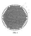
- Figure 1 shows the a nuclear reactor core 1 containing a set of fuel assemblies 2 which include a seed region and a blanket region, which form a hexagonal configuration, wherein the fuel assemblies themselves have in plan the form of a regular hexagon.
- the core 1 has the same geometric configuration and dimensions as the core in a conventional VVER-1000 light water reactor, so that the reactor can be refitted with such assemblies to form a core of 163 fuel assemblies 2.
- the difference between the core 1 and the core of the VVER-1000 reactor lies in the composition and structure of the fuel assemblies 2, as will be disclosed in greater detail below.
- the core 1 and fuel assemblies 2 presented here have been developed for use in a conventional VVER-1000 light water reactor; however, a similar core and fuel assemblies can be created for use in other standard or specially designed reactors without going beyond the scope of this invention.
- the core 1 is surrounded by a reflector 3, which preferably is comprised of a set of reflector assemblies 4.
- Each reflector assembly 4 preferably contains a mixture of water and metal of the core basket/high-pressure vessel.
- easy reflector assembly 4 may be comprised primarily of thorium oxide.
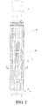
- Figure 2 shows a general view of the first alternative configuration for each of the fuel assemblies 2.
- a fuel assembly 2 contains a seed subassembly 5, a blanket subassembly 6 surrounding it, a head 7, and a tailpiece 8 with its supporting part 9 in contact with the support tube of the reactor (not shown).
- the fuel assembly has in plan the form of a regular hexagon.
- the seed subassembly 5 contains a fuel rod bundle 10 which includes a number of rods, such as 108, placed on a support grid 11, which is attached to the tailpiece of the seed subassembly 5.
- a channel 12 with a hexagonal cross section is connected to the tailpiece of the seed subassembly 5 and encloses the fuel rod bundle 10.
- a guide grid 13 for placing fuel elements 10 so as to allow their free axial movement is attached to the upper part of the channel 12.
- Each of the seed fuel elements has a kernel 14, which includes enriched uranium or reactor-grade plutonium.
- the kernel is comprised primarily of U-Zr alloy, with a uranium concentration of 25% or less by volume in the fuel composition and 19.7% uranium-235 enrichment.
- the kernel 14 is enclosed by cladding 15 of zirconium alloy and has a three-lobed profile forming spiral spacer ribs 16 ( Fig. 5 ).
- a displacer 17 of zirconium or zirconium alloy with the cross-sectional form of a regular triangle is placed along the longitudinal axis of the kernel.
- the seed fuel rods 10 may be fabricated as a single assembly unit by joint pressing (extrusion through a die).
- the axial coiling pitch of the spiral spacer ribs 16 is selected according to the condition of placing the axes of adjacent fuel rods 10 with a spacing equal to the width across corners in the cross section of a fuel rod and is 5% to 20% of the fuel rod length. Stability of the vertical arrangement of the fuel rods 10 is provided: at the bottom - by the support grid 11; at the top - by the guide grid 13; relative to the height of the core - by a system of bands (not shown) spaced evenly in the channel relative to the height of the bundle.
- the seed fuel elements 10 have a circumferential orientation such that the three-lobed profiles of any two adjacent fuel rods have a common plane of symmetry which passes through the axes of the two adjacent fuel elements ( Fig. 5 ) in at least one cross section of the fuel rod bundle.
- the seed subassembly contains a central tube 18 that forms a guide channel to accommodate controls, and peripheral tubes 19 attached to the support grid 13 which form guide channels for inserting control absorber elements based on boron carbide (B 4 C) and dysprosium titanate (Dy 2 O 3 ⁇ TiO 2 ) (not shown) and burnable absorber rods based on boron carbide and gadolinium oxide (Gd 2 O 3 ) (not shown) and are placed in the head 7 with the capability of elastic axial displacement.
- the peripheral tubes 19 that form the guide channels are made of zirconium alloy.
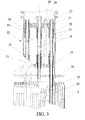
- the head 7 ( Fig. 3 ) is comprised of a spring unit, which includes precompressed springs 20, an upper plate 21, cladding 22 and a lower plate 23.
- the cladding 22 is comprised of two telescoped parts: the upper part 24 rigidly connected to the upper plate 21, and the lower part 25 rigidly connected to the lower plate 23.
- the spring unit including the springs 20 is placed inside the cladding 22.
- the peripheral tubes 19 fit into sleeves 26 and are capable of acting on the bottom ends of the sleeves (due to the presence of a step on the outer surface of the tube 19, for example).
- the sleeves 26 have flanges against which the compression springs of the spring unit 20 rest. The other ends of the springs 20 rest against the upper plate 21.
- the upper ends of the tubes 19 pass freely through openings in the upper plate 21, and the sleeves 26 pass through openings in the lower plate 23.
- the tubes 19 have stops 27 at the top ends.
- the central tube 18 is installed in a manner similar to the peripheral tubes 19, except that it passes freely through the lower plate without the use of a sleeve.
- the spring 20 through which the central tube 18 passes rests directly against the lower plate 23 of the head 7.
- a stay 28 with a stop 29 at the upper end is attached to the lower plate 23 to limit the distance between the plates 21 and 23; the stay 28 passes freely through an opening in the upper plate 21.
- a pressure element 30 in contact with the channel 12 of the seed subassembly 5 is attached to the lower plate 23. Hence a load applied to the upper plate 21 with the channel 12 fixed against axial movement is transmitted to the support grid 11 both by way of the peripheral tubes 19 and directly through the channel 12.
- the head may be constructed without the sleeves 26. In that case, all the springs 20 of the spring unit rest against the lower plate 23, and the peripheral tubes 19 pass freely through matching openings in the lower plate 23 (similar to the central tube 18). The entire load applied to the upper plate 21 with the channel 12 fixed against movement is transmitted to the support grid 11 directly through the channel 12.
- the tailpiece of the seed subassembly 5 has a locking device 31 attached to the casing which includes a cylindrical wall 32 with openings 33, balls 34 placed in the openings, and a locking element 35 with an annular slot 36 capable of axial movement.
- the locking device 31, which provides connection of the seed subassembly 5 with the tailpiece 37 of the blanket subassembly, can be also be constructed in any other form; it is important only that it provide a detachable connection of the tailpieces of the seed and blanket subassemblies.
- the blank subassembly 6 includes a frame structure 38, a bundle of fuel rods 39 situated in the frame, and a tailpiece 40.
- the frame structure 38 is comprised of six lengthwise angle units 41 with spacer grids 42 attached to them by resistance spot welding.
- Each spacer grid 42 is a honeycomb grid forming a set of cells (specifically 228) attached to the rim in outer and inner hexagons.
- the spacer grid 42 provides the required spacing of the fuel rods 39 and the required length of contact with them to allow the fuel rods 39 to slide in the spacer grid cells when they expand in length due to radiation and heat, the minimum possible sliding forces for the fuel rods to reduce internal stresses in the bundle, and the required initial tightness to avoid fretting corrosion of the fuel elements during operation.
- the spacer grids 42 have an opening in the central area to accommodate the channel 12 of the seed subassembly 5.
- the angle units are rigidly connected in the lower part to the tailpiece 40 of the blanket subassembly 6, to which the support grid 43 of the blanket subassembly to hold the fuel rods 39 is attached.
- the support grid 43 of the blanket subassembly 6 provides mechanical strength under loads in modes with normal operating conditions, modes with violations of normal operating conditions, and design accidents and also provides the hydraulic resistances required according to calculations.
- the fuel rod bundle 39 of the blanket subassembly includes a set of fuel elements (specifically 228 elements) made of a composition including 12% by volume UO 2 and 88% by volume ThO 2 with 19.7% U-235 enrichment.
- the ratio of the volume of all fuel elements of the seed subassembly V seed to the volume of all fuel elements of the blanket subassembly V blank is approximately 0.72.
- the tailpiece 40 of the blanket subassembly 6 includes a support grid 43, a casing 44 and a ring 46 rigidly connected to it by braces 45; the ring interacts with the locking device 31.
- the ends of the blanket fuel elements 39 are attached to the support grid 43.
- the support grid 43 provides mechanical strength under loads modes with normal operating conditions, modes with violations of normal operating conditions, and design accidents and also provides the required hydraulic resistance to the flow of coolant (water).
- the casing 44 can be coupled with the support tube (not shown) of the light water reactor and acts as a guide device for delivering coolant to the areas of the seed and blanket subassemblies.
- FIGS 7 - 9 show the second alternative for construction of each of the fuel assemblies 2.
- This alternative design differs from the design shown in Figs. 2 - 4 in that the seed and blanket subassemblies are not rigidly connected to each other.
- the tailpiece of the seed subassembly has a cylindrical bottom tie plate 47 instead of the locking device 31, and the casing 44 in the tailpiece of 40 of the blanket subassembly 6 lacks braces 45 and ring 46 shown in Fig. 4 .
- the cladding 22 of the head 7 ( Fig. 8 ), in contrast to the version shown in Fig. 3 is constructed in one piece, and an additional spring unit 48 is rigidly attached (e.g., welded) to it.
- the additional spring unit 48 chiefly includes several (e.g., six) additional upper plates 49 evenly distributed around the circumference and rigidly connected to the cladding 22, an additional lower plate 50 rigidly linked to the lower plate 23, cladding 51 attached to the additional plates 49 and 50, compression springs 52 and support tubes 53.
- the support tubes 53 are attached by the bottom ends to the support grid 43 of the blanket module 6.
- the upper parts of the support tubes 53 are constructed and positioned in the additional upper and lower plates 49 and 50 similar to the peripheral tubes 19; i.e., the tubes 53 fit into sleeves 26 and are capable of acting on the sleeves in an upward direction.
- the compression springs 52 of the additional spring unit 48 rest at one end against flanges of the sleeves 26 and at the other end against the additional upper plates 21.
- the upper parts of the support tubes 53 pass freely through openings in the additional upper plates 49, and the sleeves 26 pass through openings in the additional lower plate 50.
- the support tubes 53 have stops 54 at the top ends.
- the seed subassembly 5 and the blanket subassembly 6 are first assembled separately.
- the fuel elements 10 are connected to the guide grid 13 attached to the channel 12, and the central tube 18 and peripheral tubes 19 are connected to the head, in addition to being attached to the guide grid 13.
- the tubes 18 and 19 pass through sleeves 17 situated in openings in the lower plate, through the springs 20 and through openings in the upper plate 21.
- the stops 27 are attached to the top ends of the tubes (by a threaded or bayonet joint, for example).
- the fuel elements 39 of the blanket subassembly are placed in a frame structure 9 by passing them through spacer grids 42 and attaching them to the support grid 43.
- the assembled seed and blanket subassemblies are connected to form a single fuel assembly by passing the channel 12 of the seed subassembly 5 through openings in the central part of the spacer grids 42.
- the configuration of these openings in the central part of the spacer grids 42 matches the cross-sectional shape of the channel 12, so that the channel 12 passes freely through the openings.
- the locking element 35 in the tailpiece of the seed subassembly is shifted upward, so that the balls 34 situated in openings 33 of the cylindrical wall 32 are capable of movement in an annular groove 36, thus allowing the cylindrical wall 32 to pass through the ring 46.
- the locking element 36 is shifted downward.
- the balls 34 are forced out of the groove 36, shift outward in the openings 33 and jut out of the wall 32.
- the tailpiece of the seed subassembly cannot move upward in relation to the tailpiece of the blanket subassembly.
- the seed and blanket subassemblies form a single fuel assembly 2.
- the possibility of downward movement of the upper plate 21 relative to the lower plate 23 of the head 7 is provided by telescoping of the upper part 24 of the cladding 22, which is rigidly connected to the upper plate 21, and the lower part 25 of the cladding 22, which is rigidly connected to the lower plate 23.
- part of the compression force from the upper plate of the reactor is transmitted to the channel 12 of the seed subassembly by the action on the pressure element 30 of the force of a spring 20 enclosing the central tube 18 and resting directly against the lower plate 23, which is rigidly connected to the pressure element. If the head 7 does not have sleeves 26, the entire compression force is transmitted by way of the channel 12.
- Coolant passes into the fuel assembly 2 through the casing 44 of the tailpiece of the blanket subassembly 6; the coolant flow is divided into two parts, one of which runs inside the casing 12 of the seed subassembly and bathes the seed fuel elements 10, while the other runs outside the case 12 and bathes the fuel elements 39 of the blanket subassembly.
- the compression force of the head 7 acting from the upper plate of the reactor keeps the fuel elements from floating up in the specified coolant flow.
- the complete hydraulic characteristics of the fuel assembly 2 practically coincide with the characteristics of a standard fuel assembly, which ensures maintaining the resistance of the core of a VVER-1000 reactor with fuel assemblies according to one or more embodiments of the invention at the nominal level. Hence installing fuel assemblies according to one or more embodiments of this invention in a VVER-1000 will not cause a change in the coolant flow rate in the primary loop of the reactor.
- the fuel elements 10 of the seed subassembly begin to lengthen upward due to thermal and radiation expansion; the bundle of fuel elements expands independently of peripheral tubes 19, since the latter pass through the cells of the guide grid 13 with a guaranteed clearance. Hence the bundle of fuel elements 10 has no effect on the load-bearing peripheral tubes 19 and does not deform them; consequently, geometric stability of the form of the fuel assembly 2 is preserved during operation.
- the fuel elements 39 of the blanket subassembly expand in length during operation and begin to take up the free space between their ends and the head 7 due to radiation expansion.
- a fuel assembly 2 according to the second embodiment of the invention is similar, except that the casing 44 of the blanket subassembly is pressed against the support tube of the reactor by transmission of the compression force from the upper plate of the reactor through the support tubes 53, and the seed subassembly, which is not attached to the blanket subassembly, is prevented from floating up by the action of the springs 20 against the flanges of the sleeves 26, which transmit the force to the support grid 11 of the seed subassembly.
- one or more embodiments of this invention makes it possible to achieve a saving of natural uranium due to the presence of a thorium part (blanket subassembly) in the fuel assembly design, since the thorium during the depletion process accumulates secondary nuclear fuel in the form of uranium-233, burning of which makes a substantial contribution to the power output of a reactor core with such fuel assemblies.
- the fuel assembly design according to one or more embodiments of this invention makes it possible to use the fuel assembly in VVER-1000 reactors due to both mechanical and hydraulic and neutronic compatibility with the design of standard fuel assemblies.
- the complete hydraulic characteristics of a fuel assembly according to one or more embodiments of this invention practically coincide with the characteristics of a standard fuel assembly due to the presence of a system of two parallel channels formed by the seed and blanket subassemblies and joined by common distribution (delivery) and collection headers.
- the seed and blanket subassemblies are hydraulically connected in the inlet and outlet segments.
- This fuel assembly structure ensures maintaining the resistance of the core of a VVER-1000 reactor with fuel assemblies according to one or more embodiments of the invention at the nominal level. Hence installing fuel assemblies according to one or more embodiments of this invention in a VVER-1000 reactor will not cause a change in the coolant flow rate in the primary loop of the reactor.
- the ratio of hydraulic resistances between the inlet to the assembly, the active part of the blanket subassembly and the outlet from the assembly in fuel assemblies according to one or more embodiments of this invention and the standard fuel assembly are similar, which ensures hydraulic compatibility of fuel assemblies according to one or more embodiments of the invention with standard assemblies and the absence of coolant overflows between them. This makes it possible to use some fuel assemblies according to one or more embodiments of this invention in a reactor at the same time with standard fuel assemblies for the reactor.
- the seed-blanket fuel assembly according to one or more embodiments of this invention is sectional, which makes it possible to change the seed subassembly independently. Changing the seed subassembly more frequently produces more favorable conditions (with respect to neutron balance and irradiation time) for the thorium placed in the blanket subassembly of the fuel assembly.
- While the illustrated fuel elements 10 include a plurality of spacer ribs or lobes 16, such ribs/lobes 16 may be omitted. While the illustrated fuel elements 10 include displacers 17, such displacers may be omitted. While the illustrated fuel elements 10 are used in conjunction with a seed/blanket arrangement within a fuel assembly, the fuel elements 10 may alternatively be used in conjunction with a variety of other types of fuel assemblies and/or core designs. While the illustrated fuel assembly 2 utilizes a channel 12 and various other particular structures within a fuel assembly, such structures may be omitted and/or modified in a variety of ways to accommodate other assembly and/or core designs.
Landscapes
- Physics & Mathematics (AREA)
- Engineering & Computer Science (AREA)
- Plasma & Fusion (AREA)
- General Engineering & Computer Science (AREA)
- High Energy & Nuclear Physics (AREA)
- Monitoring And Testing Of Nuclear Reactors (AREA)
- Liquid Carbonaceous Fuels (AREA)
Priority Applications (1)
| Application Number | Priority Date | Filing Date | Title |
|---|---|---|---|
| EP10166457.1A EP2228801B1 (fr) | 2007-12-26 | 2008-12-23 | Élément combustible, ensemble de combustible et procédé d'utilisation d'un ensemble de combustible |
Applications Claiming Priority (2)
| Application Number | Priority Date | Filing Date | Title |
|---|---|---|---|
| PCT/RU2007/000732 WO2009082254A1 (fr) | 2007-12-26 | 2007-12-26 | Réacteur nucléaire (et variantes), assemblage de combustible constitué de modules d'allumage et de reproduction (et variantes) et crayon de combustible pour assemblage de combustible |
| US11673008P | 2008-11-21 | 2008-11-21 |
Related Child Applications (2)
| Application Number | Title | Priority Date | Filing Date |
|---|---|---|---|
| EP10166457.1A Division EP2228801B1 (fr) | 2007-12-26 | 2008-12-23 | Élément combustible, ensemble de combustible et procédé d'utilisation d'un ensemble de combustible |
| EP10166457.1A Division-Into EP2228801B1 (fr) | 2007-12-26 | 2008-12-23 | Élément combustible, ensemble de combustible et procédé d'utilisation d'un ensemble de combustible |
Publications (3)
| Publication Number | Publication Date |
|---|---|
| EP2077560A2 true EP2077560A2 (fr) | 2009-07-08 |
| EP2077560A3 EP2077560A3 (fr) | 2009-09-30 |
| EP2077560B1 EP2077560B1 (fr) | 2016-05-18 |
Family
ID=40646731
Family Applications (2)
| Application Number | Title | Priority Date | Filing Date |
|---|---|---|---|
| EP08172834.7A Active EP2077560B1 (fr) | 2007-12-26 | 2008-12-23 | Élément combustible, ensemble de combustible et procédé d'utilisation d'un ensemble de combustible |
| EP10166457.1A Active EP2228801B1 (fr) | 2007-12-26 | 2008-12-23 | Élément combustible, ensemble de combustible et procédé d'utilisation d'un ensemble de combustible |
Family Applications After (1)
| Application Number | Title | Priority Date | Filing Date |
|---|---|---|---|
| EP10166457.1A Active EP2228801B1 (fr) | 2007-12-26 | 2008-12-23 | Élément combustible, ensemble de combustible et procédé d'utilisation d'un ensemble de combustible |
Country Status (4)
| Country | Link |
|---|---|
| US (1) | US8116423B2 (fr) |
| EP (2) | EP2077560B1 (fr) |
| ES (1) | ES2599971T3 (fr) |
| HU (2) | HUE029566T2 (fr) |
Cited By (1)
| Publication number | Priority date | Publication date | Assignee | Title |
|---|---|---|---|---|
| RU2535935C2 (ru) * | 2013-03-22 | 2014-12-20 | Федеральное Государственное Бюджетное Учреждение "Петербургский институт ядерной фзизики им.Б.П.Константинова" (ФГБУ "ПИЯФ") | Тепловыделяющий элемент исследовательского реактора |
Families Citing this family (22)
| Publication number | Priority date | Publication date | Assignee | Title |
|---|---|---|---|---|
| UA98370C2 (ru) * | 2007-12-26 | 2012-05-10 | Ториум Пауэр Инк. | Ядерный реактор (варианты), топливная сборка из зажигающе-воспроизводящих модулей для ядерного реактора (варианты) и топливный элемент топливной сборки |
| JP5755568B2 (ja) * | 2008-12-25 | 2015-07-29 | トリウム・パワー、インクThorium Power,Inc. | 軽水炉核燃料集合体および軽水炉 |
| AU2015202628A1 (en) * | 2010-05-11 | 2015-06-25 | Thorium Power, Inc. | Fuel assembly |
| WO2011143172A1 (fr) * | 2010-05-11 | 2011-11-17 | Thorium Power, Inc. | Assemblage de combustible à noyau d'alliage de combustibles métalliques et son procédé de fabrication |
| US10170207B2 (en) * | 2013-05-10 | 2019-01-01 | Thorium Power, Inc. | Fuel assembly |
| US10192644B2 (en) | 2010-05-11 | 2019-01-29 | Lightbridge Corporation | Fuel assembly |
| CA2808721A1 (fr) * | 2010-08-20 | 2012-02-23 | Daniel Faber | Systeme portable pour analyser et determiner une composition elementaire d'echantillons de roche |
| RO129128B1 (ro) | 2010-09-03 | 2021-10-29 | Atomic Energy Of Canada Limited | Fascicul de combustibil nuclear conţinând toriu, şi reactor nuclear cuprinzând un astfel de fascicul |
| KR20130114675A (ko) | 2010-11-15 | 2013-10-17 | 아토믹 에너지 오브 캐나다 리미티드 | 재생된 감손 우라늄을 함유하는 핵연료, 핵연료 다발 및 그것을 포함하는 원자로 |
| KR20170052701A (ko) | 2010-11-15 | 2017-05-12 | 아토믹 에너지 오브 캐나다 리미티드 | 중성자 흡수제를 함유하는 핵연료 |
| CA2839084C (fr) | 2013-01-17 | 2020-07-14 | Atomic Energy Of Canada Limited | Conceptions de noyau heterogene et combustibles a base de thorium pour reacteurs d'eau lourde |
| US10665353B2 (en) | 2013-05-22 | 2020-05-26 | Westinghouse Electric Company Llc | VVER-1000 fuel assembly bottom nozzle |
| US11557404B2 (en) | 2013-08-23 | 2023-01-17 | Global Energy Research Associates, LLC | Method of using nanofuel in a nanofuel internal engine |
| AU2015317816B2 (en) * | 2014-09-16 | 2020-05-14 | Lightbridge Corporation | Nuclear fuel assembly |
| JP6896561B2 (ja) | 2016-09-26 | 2021-06-30 | 株式会社東芝 | 軽水炉用燃料集合体、軽水炉炉心、軽水炉用燃料集合体製造方法およびmox燃料集合体製造方法 |
| US11404177B2 (en) * | 2019-10-23 | 2022-08-02 | Battelle Energy Alliance, Llc | Reactor fuel pellets with thermally-conductive inserts, and related reactor fuel pellet arrangements |
| GB202008290D0 (en) * | 2020-06-02 | 2020-07-15 | U Battery Ltd | High temperature gas-cooked reactor core |
| JP7462586B2 (ja) | 2021-02-26 | 2024-04-05 | 株式会社東芝 | センサ |
| RU2755683C1 (ru) * | 2021-03-15 | 2021-09-20 | Акционерное общество «АКМЭ-инжиниринг» | Тепловыделяющая сборка активной зоны ядерного реактора |
| KR20240021174A (ko) | 2021-05-11 | 2024-02-16 | 클린 코어 토륨 에너지 엘엘씨 | 가압중수로를 위한 토륨 기반 연료 설계 |
| AU2022340465A1 (en) | 2021-08-28 | 2024-02-29 | Lightbridge Corporation | Multi-zone fuel element |
| CN114005554A (zh) * | 2021-10-22 | 2022-02-01 | 西安交通大学 | 一种基于螺旋十字燃料元件的氟盐冷却高温堆堆芯 |
Citations (4)
| Publication number | Priority date | Publication date | Assignee | Title |
|---|---|---|---|---|
| WO1985001826A1 (fr) | 1983-10-21 | 1985-04-25 | Alvin Radkowsky | Reacteur nucleaire du type a germes et a couche fertile |
| WO1993016477A1 (fr) | 1992-02-04 | 1993-08-19 | Radkowsky Thorium Power Corporation | Reacteur nucleaire a eau legere non-proliferative a emploi economique de thorium |
| RU2176826C2 (ru) | 1994-08-16 | 2001-12-10 | Радковски Ториум Пауэр Корпорейшн | Ядерный реактор (варианты), способ эксплуатации активной зоны ядерного реактора (варианты) и активная зона ядерного реактора (варианты) |
| RU2294570C1 (ru) | 2005-12-05 | 2007-02-27 | Открытое акционерное общество "Машиностроительный завод" | Тепловыделяющая сборка ядерного реактора |
Family Cites Families (388)
| Publication number | Priority date | Publication date | Assignee | Title |
|---|---|---|---|---|
| US2780517A (en) | 1943-04-27 | 1957-02-05 | Beppino J Fontana | Separation of uranium from foreign substances |
| US2887357A (en) | 1944-11-03 | 1959-05-19 | Glenn T Seaborg | Dry fluorine separation method |
| US2894827A (en) | 1949-10-10 | 1959-07-14 | Earl K Hyde | Uranium separation process |
| GB853511A (en) | 1949-02-22 | 1960-11-09 | Atomic Energy Authority Uk | Improvements in or relating to heat transfer systems |
| US2898185A (en) | 1949-09-14 | 1959-08-04 | George E Boyd | Adsorption method for separating thorium values from uranium values |
| US2879216A (en) | 1954-02-05 | 1959-03-24 | Jr Henry Hurwitz | Neutronic reactor |
| LU34099A1 (fr) | 1955-02-16 | 1900-01-01 | ||
| BE559120A (fr) | 1956-07-12 | |||
| FR1189249A (fr) | 1957-11-14 | 1959-10-01 | Réacteur nucléaire à liquide bouillant | |
| DE1074168B (de) | 1958-03-17 | 1960-01-28 | Westinghouse Electric Corporation, East Pittsburgh, Pa. (V. St. A.) | Spaltstoffelemcnt für heterogene Kernreaktoren, insbesondere für Druckwasserreaktoren |
| GB909637A (en) | 1958-12-10 | 1962-10-31 | Rolls Royce | Improvements in or relating to nuclear reactors |
| GB889775A (en) | 1959-01-14 | 1962-02-21 | Gen Electric Co Ltd | Improvements in and relating to thorium disilicide |
| FR1234258A (fr) | 1959-05-13 | 1960-10-17 | Barre de combustible avec canaux intérieurs pour réacteur nucléaire | |
| US3046088A (en) | 1960-06-22 | 1962-07-24 | Frederick L Horn | Protactinium extraction |
| US3105035A (en) | 1961-10-02 | 1963-09-24 | Sterling J Weems | Construction of nuclear fuel elements |
| BE628207A (fr) | 1962-02-09 | |||
| BE628206A (fr) | 1962-02-09 | |||
| NL298883A (fr) | 1963-09-06 | |||
| US3154471A (en) | 1963-11-15 | 1964-10-27 | Radkowsky Alvin | Nuclear reactor |
| US3208912A (en) | 1964-07-20 | 1965-09-28 | Jaye Seymour | Nuclear reactor fuel management method |
| US3322644A (en) | 1964-07-22 | 1967-05-30 | Physies Internat Company | Core element for a breeder nuclear reactor |
| BE651866A (fr) | 1964-08-14 | 1965-02-15 | Euratom | Crayon de combustible tubulaire à gaine mince souple pour réacteurs nucléaires |
| US3285825A (en) | 1964-09-16 | 1966-11-15 | Atomic Power Dev Ass Inc | Reinforced ceramic fuel elements |
| US3219535A (en) * | 1964-12-15 | 1965-11-23 | Thomas R Robbins | Nuclear reactor control means |
| DE1514124A1 (de) | 1965-03-05 | 1969-09-04 | Licentia Gmbh | Hohlzylindrisches Kernreaktor-Brennelement |
| FR1444002A (fr) | 1965-04-28 | 1966-07-01 | Akad Wissenschaften Ddr | élément combustible et son procédé de fabrication |
| US3309277A (en) | 1965-05-17 | 1967-03-14 | Jaye Seymour | Nuclear reactor and method of fuel management therefor |
| FR1444181A (fr) | 1965-05-19 | 1966-07-01 | Commissariat Energie Atomique | élément combustible de réacteur nucléaire |
| FR1462237A (fr) | 1965-07-22 | 1966-04-15 | Commissariat Energie Atomique | Réacteur nucléaire refroidi par métal liquide |
| US3335060A (en) | 1965-09-20 | 1967-08-08 | Richard L Diener | Seed-blanket neutronic reactor |
| US3339631A (en) | 1966-07-13 | 1967-09-05 | James A Mcgurty | Heat exchanger utilizing vortex flow |
| US3378453A (en) | 1966-07-13 | 1968-04-16 | Atomic Energy Commission Usa | High heat flux neutronic fuel element |
| BE694504A (fr) | 1967-02-23 | 1967-07-31 | ||
| US3486973A (en) | 1967-04-11 | 1969-12-30 | Westinghouse Electric Corp | Breeder reactor |
| US3394049A (en) | 1967-09-28 | 1968-07-23 | Atomic Energy Commission Usa | Nuclear reactor core configuration |
| US3546068A (en) | 1967-11-01 | 1970-12-08 | Babcock & Wilcox Co | Nuclear reactor core construction |
| US3660228A (en) | 1967-11-06 | 1972-05-02 | Teledyne Inc | Nuclear reactor control with reflector and absorber means |
| US3577225A (en) | 1968-07-18 | 1971-05-04 | Atomic Energy Commission | Method for separating uranium, protactinium, and rare earth fission products from spent molten fluoride salt reactor fuels |
| GB1279084A (en) | 1968-11-15 | 1972-06-21 | Atomic Energy Authority Uk | Improvements in or relating to nuclear reactors |
| US3640844A (en) | 1969-11-07 | 1972-02-08 | Atomic Energy Commission | Power-flattened seed-blanket reactor core |
| US3736227A (en) | 1970-06-01 | 1973-05-29 | Continental Oil Co | Nuclear reactor fuel element spacer assembly lock |
| US3714322A (en) | 1970-06-10 | 1973-01-30 | Atomic Energy Commission | Method for preparing high purity 233 uranium |
| US3859165A (en) | 1970-07-29 | 1975-01-07 | Atomic Energy Commission | Epithermal to intermediate spectrum pressurized heavy water breeder reactor |
| US3671392A (en) | 1971-03-15 | 1972-06-20 | Atomic Energy Commission | Light-water breeder reactor |
| US3814667A (en) | 1971-05-20 | 1974-06-04 | Combustion Eng | Fuel assembly hold-down device |
| USRE31583E (en) | 1971-05-20 | 1984-05-08 | Combustion Engineering, Inc. | Fuel assembly hold-down device |
| US3801734A (en) | 1971-12-23 | 1974-04-02 | Combustion Eng | Reactor-fuel assembly hold down |
| US3847736A (en) | 1972-01-24 | 1974-11-12 | Combustion Eng | Flow twister for a nuclear reactor |
| US3853703A (en) | 1972-07-03 | 1974-12-10 | Combustion Eng | Fuel assembly hold-up device |
| US4077835A (en) | 1972-11-24 | 1978-03-07 | Westinghouse Electric Corporation | Nuclear reactor with self-orificing radial blanket |
| DE2307925A1 (de) | 1973-02-17 | 1974-08-29 | Bayer Ag | Herstellung von fluoriden aus kieselfluorwasserstoffsaeure |
| US4393510A (en) | 1973-07-20 | 1983-07-12 | Pacific Nuclear Fuels, Inc. | Reactor for production of U-233 |
| US4202793A (en) | 1973-10-26 | 1980-05-13 | Agip Nucleare S.P.A. | Production of microspheres of thorium oxide, uranium oxide and plutonium oxide and their mixtures containing carbon |
| US3957575A (en) | 1974-04-16 | 1976-05-18 | The United States Of America As Represented By The United States Energy Research And Development Administration | Mechanical design of a light water breeder reactor |
| US3998692A (en) | 1974-07-09 | 1976-12-21 | The United States Of America As Represented By The United States Energy Research And Development Administration | Nuclear reactor for breeding U233 |
| US3960655A (en) * | 1974-07-09 | 1976-06-01 | The United States Of America As Represented By The United States Energy Research And Development Administration | Nuclear reactor for breeding U233 |
| US3971575A (en) | 1974-11-29 | 1976-07-27 | Combustion Engineering, Inc. | Releasable locking device |
| UST947011I4 (fr) | 1975-04-17 | 1976-06-01 | ||
| US4029740A (en) | 1975-11-24 | 1977-06-14 | Rockwell International Corporation | Method of producing metal nitrides |
| DE2601684C3 (de) | 1976-01-17 | 1978-12-21 | Hobeg Hochtemperaturreaktor-Brennelement Gmbh, 6450 Hanau | Verfahren zur Herstellung von Brenn- und Brutstoff-Partikeln |
| US4078967A (en) | 1976-07-26 | 1978-03-14 | Combustion Engineering, Inc. | Holddown device for nuclear fuel assembly |
| US4072564A (en) | 1976-09-24 | 1978-02-07 | The Babcock & Wilcox Company | Motion restraining apparatus for a nuclear reactor |
| US4192716A (en) | 1976-12-27 | 1980-03-11 | Combustion Engineering Inc. | Peripheral pin alignment system for fuel assemblies |
| US4111348A (en) | 1977-03-09 | 1978-09-05 | Westinghouse Electric Corp. | Grid braze application mold |
| DE2733384C2 (de) | 1977-07-23 | 1982-02-25 | Kernforschungsanlage Jülich GmbH, 5170 Jülich | Verfahren zur Herstellung von Brutstoff- oder Brenn- und Brutstoffkernen für Brennelemente von Kernreaktoren |
| DE2742946C2 (de) | 1977-09-23 | 1979-07-26 | Kraftwerk Union Ag, 4330 Muelheim | Federelement für die Niederhaltung von Kernreaktorbrennelementen |
| IL53122A (en) | 1977-10-13 | 1980-11-30 | Univ Ramot | Nuclear reactor and method of operating same |
| US4194948A (en) | 1977-11-14 | 1980-03-25 | General Atomic | Locking support for nuclear fuel assemblies |
| US4235669A (en) | 1978-03-30 | 1980-11-25 | The United States Of America As Represented By The United States Department Of Energy | Nuclear reactor composite fuel assembly |
| DE2819734C2 (de) | 1978-05-05 | 1986-10-16 | Kernforschungszentrum Karlsruhe Gmbh, 7500 Karlsruhe | Kernreaktor |
| US4309251A (en) | 1978-11-13 | 1982-01-05 | Combustion Engineering, Inc. | Nuclear fuel assembly holddown apparatus |
| US4298434A (en) | 1978-11-13 | 1981-11-03 | Combustion Engineering, Inc. | Bottom mounted fuel holddown mechanism |
| US4268357A (en) | 1978-11-24 | 1981-05-19 | Combustion Engineering, Inc. | Positive lock holddown device |
| US4292278A (en) | 1979-02-21 | 1981-09-29 | Wyoming Mineral Corp. | Purification of wet process phosphoric acid as a pretreatment step in the recovery of uranium |
| US4285771A (en) | 1979-02-22 | 1981-08-25 | Westinghouse Electric Corp. | Nuclear core and fuel assemblies |
| US4324618A (en) | 1979-06-08 | 1982-04-13 | The Babcock & Wilcox Company | Fuel element assembly |
| US4304631A (en) | 1979-07-02 | 1981-12-08 | The Babcock & Wilcox Company | Control component retainer |
| US4320093A (en) | 1979-11-13 | 1982-03-16 | Bohumil Volesky | Separation of uranium by biosorption |
| FR2479535A1 (fr) | 1980-03-26 | 1981-10-02 | Commissariat Energie Atomique | Dispositif de limitation des effets de la poussee hydraulique axiale s'exercant sur des assemblages combustibles de reacteurs nucleaires |
| US4344912A (en) | 1980-06-16 | 1982-08-17 | The United States Of America As Represented By The United States Department Of Energy | Method of increasing the deterrent to proliferation of nuclear fuels |
| US4381284A (en) | 1980-12-16 | 1983-04-26 | Westinghouse Electric Corp. | Fuel assembly for a nuclear reactor |
| SE424929B (sv) | 1980-12-19 | 1982-08-16 | Asea Atom Ab | Brenslepatron avsedd for en kokvattenreaktor |
| JPS57194390A (en) | 1981-05-26 | 1982-11-29 | Tokyo Shibaura Electric Co | Fixing device for nuclear fuel assembly |
| US4474398A (en) | 1981-06-26 | 1984-10-02 | Westinghouse Electric Corp. | Fuel assembly locking apparatus |
| US4450016A (en) | 1981-07-10 | 1984-05-22 | Santrade Ltd. | Method of manufacturing cladding tubes of a zirconium-based alloy for fuel rods for nuclear reactors |
| JPS5819592A (ja) | 1981-07-27 | 1983-02-04 | 株式会社日立製作所 | 高速炉の炉心の出力分布平坦化方法とその方法に用いる燃料集合体 |
| KR860000966B1 (ko) | 1981-11-30 | 1986-07-23 | 엘돈 에이취. 루터 | 원자로 연료 조립체용 힘 방지 그리드 |
| FR2520148B1 (fr) | 1982-01-18 | 1986-01-10 | Commissariat Energie Atomique | Piece d'extremite d'assemblage combustible de reacteur nucleaire comportant un levier rigide rappele elastiquement |
| JPS58140678A (ja) | 1982-02-16 | 1983-08-20 | 動力炉・核燃料開発事業団 | 核燃料集合体用スペ−サ |
| US4560532A (en) | 1982-04-15 | 1985-12-24 | Westinghouse Electric Corp. | Nuclear fuel assembly |
| US4666664A (en) | 1982-04-15 | 1987-05-19 | Westinghouse Electric Corp. | Coolant flow paths within a nuclear fuel assembly |
| US4584167A (en) | 1982-04-23 | 1986-04-22 | Westinghouse Electric Corp. | Blanket management method for liquid metal fast breeder reactors |
| US4495136A (en) | 1982-05-11 | 1985-01-22 | Westinghouse Electric Corp. | Maximum power capability blanket for nuclear reactors |
| US4968476A (en) | 1982-05-14 | 1990-11-06 | Touro College | Light water breeder reactor using a uranium-plutonium cycle |
| SE434679B (sv) | 1982-07-01 | 1984-08-06 | Asea Ab | Anordning vid hermetiskt slutna lastceller for eliminering av inverkan pa metverdet av en skillnad mellan trycket i ett givarrum och atmosferstrycket |
| US4544522A (en) | 1982-08-20 | 1985-10-01 | General Electric Company | Nuclear fuel assembly spacer |
| US4508679A (en) | 1982-08-20 | 1985-04-02 | General Electric Company | Nuclear fuel assembly spacer |
| US4880607A (en) | 1982-12-20 | 1989-11-14 | Phillips Petroleum Company | Recovering mineral values from ores |
| US4578240A (en) | 1983-01-03 | 1986-03-25 | Westinghouse Electric Corp. | Nuclear reactor fuel assembly spacer grid |
| JPS59137887A (ja) | 1983-01-13 | 1984-08-08 | ウエスチングハウス エレクトリツク コ−ポレ−シヨン | 原子炉燃料集合体 |
| FR2544538B1 (fr) | 1983-04-13 | 1985-08-02 | Fragema Framatome & Cogema | Dispositif anti-envol pour reacteur nucleaire |
| US5386439A (en) | 1983-09-13 | 1995-01-31 | Framatome | Spectral shift nuclear reactor with improved efficiency |
| US4615862A (en) | 1983-12-21 | 1986-10-07 | Westinghouse Electric Corp. | Nuclear reactor with fuel assembly support means |
| US4572816A (en) | 1983-12-21 | 1986-02-25 | Westinghouse Electric Corp. | Reconstituting a nuclear reactor fuel assembly |
| US4589929A (en) | 1984-02-09 | 1986-05-20 | Kraftwerk Union Aktiengesellschaft | Method for treating the surface of finished parts, particularly the surface of tubes and spacers formed of zirconium alloys, for nuclear reactor fuel assemblies |
| FR2561151B1 (fr) | 1984-03-13 | 1987-08-28 | Fragema Framatome & Cogema | Procede et installation de soudage de grilles pour assemblage de combustible nucleaire |
| FR2562314B1 (fr) | 1984-03-27 | 1989-02-17 | Commissariat Energie Atomique | Procede pour recuperer le plutonium contenu dans des dechets solides |
| JPH0658437B2 (ja) | 1984-11-06 | 1994-08-03 | 株式会社日立製作所 | 原子力プラントの放射能低減方法 |
| US4684495A (en) | 1984-11-16 | 1987-08-04 | Westinghouse Electric Corp. | Fuel assembly bottom nozzle with integral debris trap |
| US4671927A (en) | 1984-12-03 | 1987-06-09 | Westinghouse Electric Corp. | Nuclear fuel rod containing a hybrid gadolinium oxide, boron carbide burnable absorber |
| US4664880A (en) | 1984-12-07 | 1987-05-12 | Westinghouse Electric Corp. | Wire mesh debris trap for a fuel assembly |
| US4670213A (en) | 1985-02-12 | 1987-06-02 | Westinghouse Electric Corp. | Removable top nozzle subassembly for a reconstitutable nuclear fuel assembly |
| US4699758A (en) | 1985-04-02 | 1987-10-13 | Westinghouse Electric Corp. | Reusable locking tube in a reconstitutable fuel assembly |
| US4678627A (en) | 1985-04-04 | 1987-07-07 | Westinghouse Electric Corp. | Debris-retaining trap for a fuel assembly |
| US4671924A (en) | 1985-05-02 | 1987-06-09 | Westinghouse Electric Corp. | Hold-down device of fuel assembly top nozzle employing leaf springs |
| US4716015A (en) | 1985-05-15 | 1987-12-29 | Westinghouse Electric Corp. | Modular nuclear fuel assembly design |
| US4678632A (en) | 1985-06-05 | 1987-07-07 | Westinghouse Electric Corp. | Nuclear fuel assembly grid with predetermined grain orientation |
| US4762676A (en) | 1985-07-05 | 1988-08-09 | Westinghouse Electric Corp. | Top nozzle adapter plate with fuel rod capture grid having pressure drop adjusting means |
| FR2585499B1 (fr) | 1985-07-29 | 1989-10-27 | Fragema Framatome & Cogema | Dispositif de maintien hydraulique pour assemblage combustible nucleaire et reacteur nucleaire en comportant application |
| US4702883A (en) | 1985-08-05 | 1987-10-27 | Westinghouse Electric Corp. | Reconstitutable fuel assembly having removable upper stops on guide thimbles |
| US4652425A (en) | 1985-08-08 | 1987-03-24 | Westinghouse Electric Corp. | Bottom grid mounted debris trap for a fuel assembly |
| FR2589614B1 (fr) | 1985-08-09 | 1988-01-08 | Fragema Framatome & Cogema | Assemblage combustible nucleaire a structure de maintien et dispositif anti-envol |
| US4692304A (en) | 1985-12-23 | 1987-09-08 | Westinghouse Electric Corp. | Removable and reusable locking pin for top nozzle assembly and disassembly |
| US4842814A (en) | 1986-02-03 | 1989-06-27 | Hitachi, Ltd. | Nuclear reactor fuel assembly |
| US4699761A (en) | 1986-04-30 | 1987-10-13 | Westinghouse Electric Corp. | Integral reusable locking arrangement for a removable top nozzle subassembly of a reconstitutable nuclear fuel assembly |
| US6278757B1 (en) | 1986-09-17 | 2001-08-21 | Hitachi, Ltd | Fuel assembly and nuclear reactor |
| GB8626238D0 (en) | 1986-11-03 | 1986-12-03 | Nat Nuclear Corp Ltd | Nuclear reactor core restraint |
| FR2606201B1 (fr) | 1986-11-03 | 1988-12-02 | Electricite De France | Procede de gestion du coeur d'un reacteur nucleaire a eau pressurisee |
| EP0277533A1 (fr) | 1987-01-28 | 1988-08-10 | Siemens Aktiengesellschaft | Elément combustible pour réacteur nucléaire |
| US4765909A (en) | 1987-04-23 | 1988-08-23 | Gte Laboratories Incorporated | Ion exchange method for separation of scandium and thorium |
| US4900507A (en) | 1987-05-05 | 1990-02-13 | Westinghouse Electric Corp. | Nuclear fuel assembly debris filter bottom nozzle |
| ES2034312T3 (es) | 1987-06-23 | 1993-04-01 | Framatome | Procedimiento de fabricacion de un tubo de aleacion de circonio para reactor nuclear y aplicaciones. |
| DE3865789D1 (de) | 1987-08-24 | 1991-11-28 | Framatome Sa | Verfahren zur herstellung eines abstandhalters fuer ein brennstabbuendel eines kernreaktors. |
| FR2623792B1 (fr) | 1987-11-27 | 1991-02-15 | Rhone Poulenc Chimie | Procede de separation du thorium et des terres rares d'un concentre de fluorures de ces elements |
| FR2627321B1 (fr) | 1988-02-11 | 1992-08-14 | Framatome Sa | Equipements internes superieurs de reacteur nucleaire muni d'un dispositif de separation des debits |
| US4832905A (en) | 1988-04-15 | 1989-05-23 | Combustion Engineering, Inc. | Lower end fitting debris collector |
| FR2632657B1 (fr) | 1988-06-10 | 1990-09-28 | Cogema | Procede de traitement d'un minerai uranifere en limitant les pertes de reactifs |
| US4942016A (en) | 1988-09-19 | 1990-07-17 | General Electric Company | Nuclear fuel element |
| US4879086A (en) | 1988-09-27 | 1989-11-07 | The United States Of America As Represented By The United States Department Of Energy | Neutron economic reactivity control system for light water reactors |
| JP2559136B2 (ja) | 1988-10-26 | 1996-12-04 | 三菱マテリアル株式会社 | 原子炉燃料被覆管支持格子用Zr合金 |
| US5024807A (en) | 1988-12-05 | 1991-06-18 | Combustion Engineering, Inc. | Debris catching spring detent spacer grid |
| US4986960A (en) | 1989-01-30 | 1991-01-22 | The Babcock & Wilcox Company | Two piece end fitting with hairpin springs |
| US5136619A (en) | 1989-02-13 | 1992-08-04 | The United States Of America As Represented By The United States Department Of Energy | Thermal breeder fuel enrichment zoning |
| GB8906004D0 (en) | 1989-03-15 | 1989-04-26 | British Nuclear Fuels Plc | A process for producing uranium hexafluoride |
| US5024426A (en) | 1989-03-17 | 1991-06-18 | Advanced Nuclear Fuels Corporation | Bimetallic spring member for radiation environment |
| FR2646004B1 (fr) | 1989-04-12 | 1993-12-24 | Framatome | Plaque de filtration associee a un embout inferieur d'un assemblage combustible d'un reacteur nucleaire |
| JPH0713664B2 (ja) | 1989-04-26 | 1995-02-15 | 株式会社日立製作所 | 燃料集合体および燃料スペーサ |
| FR2646548B1 (fr) | 1989-04-28 | 1993-11-26 | Framatome | Grille a ressorts de maintien pour assemblage combustible nucleaire |
| US5024810A (en) | 1989-05-22 | 1991-06-18 | Combustion Engineering, Inc. | Support grid with integral inclined waves |
| US5026516A (en) | 1989-05-25 | 1991-06-25 | General Electric Company | Corrosion resistant cladding for nuclear fuel rods |
| US5024809A (en) | 1989-05-25 | 1991-06-18 | General Electric Company | Corrosion resistant composite claddings for nuclear fuel rods |
| US5073336A (en) | 1989-05-25 | 1991-12-17 | General Electric Company | Corrosion resistant zirconium alloys containing copper, nickel and iron |
| US4986957A (en) | 1989-05-25 | 1991-01-22 | General Electric Company | Corrosion resistant zirconium alloys containing copper, nickel and iron |
| FR2649417B1 (fr) | 1989-07-06 | 1992-05-07 | Cezus Co Europ Zirconium | Procede d'obtention d'uranium a partir d'oxyde et utilisant une voie chlorure |
| US4997596A (en) | 1989-09-18 | 1991-03-05 | General Electric Company | Fissionable nuclear fuel composition |
| FR2652591B1 (fr) | 1989-10-03 | 1993-10-08 | Framatome | Procede d'oxydation superficielle d'une piece en metal passivable, et elements d'assemblage combustible en alliage metallique revetus d'une couche d'oxyde protectrice. |
| US5037605A (en) | 1989-10-13 | 1991-08-06 | B&W Fuel Company | Nuclear fuel assembly debris filter |
| US5094802A (en) | 1989-10-13 | 1992-03-10 | B&W Fuel Company | Nuclear fuel assembly debris filter |
| US5009837A (en) | 1989-11-03 | 1991-04-23 | Westinghouse Electric Corp. | Axially modular fuel assembly and rod for optimal fuel utilization |
| SE464994B (sv) | 1989-11-14 | 1991-07-08 | Asea Atom Ab | Braenslepatron foer en kokarreaktor |
| JPH03158485A (ja) | 1989-11-16 | 1991-07-08 | Tanaka Kikinzoku Kogyo Kk | ウラニル塩の還元方法 |
| JPH0830748B2 (ja) | 1989-12-06 | 1996-03-27 | 三菱原子燃料株式会社 | 支持格子 |
| US5002726A (en) | 1989-12-27 | 1991-03-26 | General Electric Company | Nuclear fuel assembly spacer and loop spring with enhanced flexibility |
| US5085827A (en) | 1989-12-27 | 1992-02-04 | General Electric Company | Nuclear fuel assembly spacer and loop spring with enhanced flexibility |
| US5019327A (en) | 1990-01-25 | 1991-05-28 | General Electric Company | Fuel assembly transfer basket for pool type nuclear reactor vessels |
| US5089210A (en) | 1990-03-12 | 1992-02-18 | General Electric Company | Mox fuel assembly design |
| US5069864A (en) | 1990-04-16 | 1991-12-03 | General Electric Company | Nuclear fuel assembly spacer and spring |
| US5030412A (en) | 1990-05-04 | 1991-07-09 | Advanced Nuclear Fuels Corporation | Fuel assembly debris screen |
| US5221515A (en) | 1990-05-07 | 1993-06-22 | Franco-Belge De Fabrication De Combustible | Method for manufacturing grids for a nuclear fuel assembly |
| US5032351A (en) | 1990-05-11 | 1991-07-16 | General Electric Company | Modified cross point spacer apparatus and construction |
| FR2665292B1 (fr) | 1990-07-24 | 1992-11-13 | Framatome Sa | Grille additionnelle pour assemblage combustible de reacteur nucleaire et assemblage en comportant application. |
| US5149491A (en) | 1990-07-10 | 1992-09-22 | General Electric Company | Seed and blanket fuel arrangement for dual-phase nuclear reactors |
| US5110539A (en) | 1990-12-07 | 1992-05-05 | Combustion Engineering, Inc. | Spacer grid assembly fixture |
| FR2665293B1 (fr) | 1990-07-24 | 1993-12-24 | Framatome | Procede de fabrication de grille a cellules calibrees pour assemblage combustible nucleaire. |
| US5194216A (en) | 1990-08-22 | 1993-03-16 | Nuclear Assurance Corporation | Guide plate for locating rods in an array |
| US5053191A (en) | 1990-09-13 | 1991-10-01 | Combustion Engineering, Inc. | Fuel assembly holddown spring |
| US5141701A (en) | 1990-09-14 | 1992-08-25 | Combustion Engineering, Inc. | Bottom nozzle to lower grid attachment |
| EP0549639B1 (fr) | 1990-09-18 | 1995-11-15 | Siemens Aktiengesellschaft | Element combustible pour reacteur a eau bouillante presentant un support compose d'elements standardises |
| JP3036810B2 (ja) | 1990-09-19 | 2000-04-24 | 株式会社日立製作所 | 燃料集合体 |
| US5209899A (en) | 1990-10-25 | 1993-05-11 | General Electric Company | Composite spacer with inconel grid and zircaloy band |
| US5089221A (en) | 1990-10-25 | 1992-02-18 | General Electric Company | Composite spacer with Inconel grid and Zircaloy band |
| JP2945459B2 (ja) | 1990-10-25 | 1999-09-06 | 株式会社日立製作所 | 燃料集合体 |
| EP0689209A1 (fr) | 1990-11-28 | 1995-12-27 | Hitachi, Ltd. | Procédé d'exploitation d'un réacteur nucléaire comportant plusieurs enveloppes d'assemblages combustibles et de fabrication de telles enveloppes |
| ES2095937T3 (es) | 1990-12-05 | 1997-03-01 | Siemens Ag | Elemento combustible o elemento de control con un enclavamiento liberable entre la caja y la parte extrema superior o la inferior del elemento. |
| EP0501259B1 (fr) | 1991-02-25 | 1995-08-02 | Hitachi, Ltd. | Assemblage combustible avec enveloppe |
| US5192495A (en) | 1991-02-27 | 1993-03-09 | Babcock & Wilcox Company | Sic barrier overcoating and infiltration of fuel compact |
| SE468110B (sv) | 1991-03-13 | 1992-11-02 | Asea Atom Ab | Spridare foer sammanhaallande av braenslestavar i en kaernreaktors braenslepatron |
| US5188797A (en) | 1991-04-03 | 1993-02-23 | Combustion Engineering, Inc. | Extended weld tab for fuel assembly grid |
| US5147597A (en) | 1991-04-09 | 1992-09-15 | Electric Power Research Institute | Prestabilized chromium protective film to reduce radiation buildup |
| US5200142A (en) | 1991-04-18 | 1993-04-06 | Westinghouse Electric Corp. | Nuclear fuel assembly top nozzle with improved peripheral hold-down assembly |
| US5186891A (en) | 1991-05-17 | 1993-02-16 | General Electric Company | Swirl vanes in inconel spacer |
| US5259009A (en) | 1991-08-19 | 1993-11-02 | Siemens Power Corporation | Boiling water reactor fuel rod assembly with fuel rod spacer arrangement |
| EP0529128B1 (fr) | 1991-08-28 | 1995-10-18 | Siemens Aktiengesellschaft | Assemblage combustible pour réacteur nucléaire avec ressorts à lames |
| JP2638351B2 (ja) | 1991-09-20 | 1997-08-06 | 株式会社日立製作所 | 燃料集合体 |
| US5259010A (en) | 1991-09-30 | 1993-11-02 | B&W Nuclear Service Company | Replacement spacer pin with locking keys |
| FR2682213B1 (fr) | 1991-10-04 | 1994-01-07 | Framatome | Embout inferieur d'un assemblage combustible pour reacteur nucleaire refroidi a l'eau. |
| US5135728A (en) | 1992-01-03 | 1992-08-04 | Karraker David G | Method for dissolving delta-phase plutonium |
| US5386440A (en) | 1992-01-10 | 1995-01-31 | Hitachi, Ltd. | Boiling water reactor |
| FR2686445B1 (fr) | 1992-01-17 | 1994-04-08 | Framatome Sa | Crayon de combustible nucleaire et procede de fabrication de la gaine d'un tel crayon. |
| US5219519A (en) | 1992-02-21 | 1993-06-15 | General Electric Company | Increased fuel column height for boiling water reactor fuel rods |
| US5267291A (en) | 1992-02-21 | 1993-11-30 | General Electric Company | Spacer band with optimized fuel bundle to channel clearance in a boiling water reactor |
| DE9206038U1 (de) | 1992-02-28 | 1992-07-16 | Siemens AG, 80333 München | Werkstoff und Strukturteil aus modifiziertem Zirkaloy |
| SE470032B (sv) | 1992-03-17 | 1993-10-25 | Asea Atom Ab | Spridare för sammanhållning av ett antal långsträckta bränslestavar till ett knippe för placering i en kärnreaktor av BWR- eller PWP-typ. |
| US5247550A (en) | 1992-03-27 | 1993-09-21 | Siemens Power Corporation | Corrosion resistant zirconium liner for nuclear fuel rod cladding |
| US5278883A (en) | 1992-03-30 | 1994-01-11 | Siemens Power Corporation | Low pressure drop spacer for nuclear fuel assemblies |
| US5297176A (en) | 1992-05-22 | 1994-03-22 | Westinghouse Electric Corp. | Remotely replaceable fuel assembly alignment pin |
| US5241570A (en) | 1992-06-08 | 1993-08-31 | General Electric Company | Core-control assembly with a fixed fuel support |
| US5283821A (en) | 1992-06-29 | 1994-02-01 | Combustion Engineering, Inc. | Split-cone spacer grid |
| US5307393A (en) | 1992-06-29 | 1994-04-26 | Combustion Engineering, Inc. | Split vane alternating swirl mixing grid |
| FR2692880B1 (fr) | 1992-06-29 | 1994-09-02 | Pechiney Uranium | Procédé d'électro-fluoration sélective d'alliages ou de mélanges métalliques à base d'uranium. |
| US5271053A (en) | 1992-07-02 | 1993-12-14 | Combustion Engineering, Inc. | Holddown leaf spring assembly |
| FR2693476B1 (fr) | 1992-07-09 | 1994-09-02 | Cezus Co Europ Zirconium | Produit extérieurement en alliage de Zr, son procédé de fabrication et son utilisation. |
| US5272742A (en) | 1992-07-20 | 1993-12-21 | B&W Fuel Company | Upper end fitting |
| US5286946A (en) | 1992-09-02 | 1994-02-15 | Beloit Technologies, Inc. | Method and apparatus for securing an end of a headbox flow tube |
| US5349618A (en) | 1992-09-09 | 1994-09-20 | Ehud Greenspan | BWR fuel assembly having oxide and hydride fuel |
| US5282231A (en) | 1992-09-23 | 1994-01-25 | Siemens Power Corporation | Lower tie plate cast frame |
| US5274685A (en) | 1992-09-24 | 1993-12-28 | Siemens Power Corporation | Non-levitating PWR fuel assembly |
| US5243635A (en) | 1992-09-25 | 1993-09-07 | Combustion Engineering, Inc. | Fuel rod capturing grid spring and arch |
| US5299246A (en) | 1992-09-25 | 1994-03-29 | Combustion Engineering, Inc. | Shape-memory alloys in the construction of nuclear fuel spacer grids |
| CA2146875A1 (fr) | 1992-10-13 | 1994-04-28 | Martin-Benno Buttner | Espaceur grillage pour element combustible de reacteur nucleaire |
| FR2697010B1 (fr) | 1992-10-19 | 1995-02-24 | Rhone Poulenc Chimie | Procédé de traitement des composés solubles du thorium et nouveau phosphate de thorium ainsi obtenu. |
| US5301218A (en) | 1992-10-22 | 1994-04-05 | General Electric Company | Tolerant metal fuel/cladding barrier and related method of installation |
| SE506174C2 (sv) | 1992-12-18 | 1997-11-17 | Asea Atom Ab | Metod att framställa kärnbränsleelement |
| US5278882A (en) | 1992-12-30 | 1994-01-11 | Combustion Engineering, Inc. | Zirconium alloy with superior corrosion resistance |
| US5483564A (en) | 1993-04-12 | 1996-01-09 | General Electric Company | Lower tie plate strainers including double corrugated strainers for boiling water reactors |
| US5384814A (en) | 1993-04-12 | 1995-01-24 | General Electric Company | Lower tie plate strainers for boiling water reactors |
| US5375154A (en) | 1993-04-15 | 1994-12-20 | General Electric Company | Reduced pressure drop spacer for boiling water reactor fuel bundles |
| US5618356A (en) | 1993-04-23 | 1997-04-08 | General Electric Company | Method of fabricating zircaloy tubing having high resistance to crack propagation |
| US5437747A (en) | 1993-04-23 | 1995-08-01 | General Electric Company | Method of fabricating zircalloy tubing having high resistance to crack propagation |
| US5519748A (en) | 1993-04-23 | 1996-05-21 | General Electric Company | Zircaloy tubing having high resistance to crack propagation |
| SE509238C2 (sv) | 1993-07-05 | 1998-12-21 | Asea Atom Ab | Reaktorhärd |
| US5383228A (en) | 1993-07-14 | 1995-01-17 | General Electric Company | Method for making fuel cladding having zirconium barrier layers and inner liners |
| US5524032A (en) | 1993-07-14 | 1996-06-04 | General Electric Company | Nuclear fuel cladding having an alloyed zirconium barrier layer |
| US5517540A (en) | 1993-07-14 | 1996-05-14 | General Electric Company | Two-step process for bonding the elements of a three-layer cladding tube |
| US5341407A (en) | 1993-07-14 | 1994-08-23 | General Electric Company | Inner liners for fuel cladding having zirconium barriers layers |
| US5469481A (en) | 1993-07-14 | 1995-11-21 | General Electric Company | Method of preparing fuel cladding having an alloyed zirconium barrier layer |
| JP3094195B2 (ja) | 1993-08-10 | 2000-10-03 | 株式会社小糸製作所 | ヘッドランプレベリング機構 |
| US5390221A (en) | 1993-08-23 | 1995-02-14 | General Electric Company | Debris filters with flow bypass for boiling water reactors |
| SE509202C2 (sv) | 1993-09-20 | 1998-12-14 | Asea Atom Ab | Spridare och bränslepatron för en kokarreaktor |
| US5417780A (en) | 1993-10-28 | 1995-05-23 | General Electric Company | Process for improving corrosion resistance of zirconium or zirconium alloy barrier cladding |
| WO1995012203A1 (fr) | 1993-10-29 | 1995-05-04 | Carlo Rubbia | Amplificateur d'energie destine a la production d'energie nucleaire 'propre' grace a un accelerateur de faisceau de particules |
| SE510816C2 (sv) | 1993-11-02 | 1999-06-28 | Asea Atom Ab | Spridare och bränslepatron för en kärnreaktor |
| US5390220A (en) | 1993-11-29 | 1995-02-14 | General Electric Company | Lower tie plate strainers including helical spring strainers for boiling water reactors |
| US5345483A (en) | 1993-12-02 | 1994-09-06 | General Electric Company | Lower tie plate strainers having double plate with offset holes for boiling water reactors |
| US5452334A (en) | 1993-12-17 | 1995-09-19 | Siemens Power Corporation | Pressurized water reactor nuclear fuel assembly with disengaging upper tie plate corner post |
| US5440599A (en) | 1994-02-03 | 1995-08-08 | Combustion Engineering, Inc. | Spacer grid with integral "side supported" flow directing vanes |
| US5488634A (en) | 1994-02-10 | 1996-01-30 | General Electric Company | Lower tie plate debris catcher for a nuclear reactor |
| US5538701A (en) | 1994-02-28 | 1996-07-23 | The Regents Of The University Of California, Office Of Technology Transfer | Process to remove actinides from soil using magnetic separation |
| US5434898A (en) | 1994-03-14 | 1995-07-18 | Siemens Power Corporation | Nuclear fuel assembly |
| US5438598A (en) | 1994-03-15 | 1995-08-01 | B&W Fuel Company | Combined lower end fitting and debris filter |
| JP3094778B2 (ja) | 1994-03-18 | 2000-10-03 | 株式会社日立製作所 | 軽水炉用燃料集合体とそれに用いられる部品及び合金並びに製造法 |
| US5436947A (en) | 1994-03-21 | 1995-07-25 | General Electric Company | Zirconium alloy fuel cladding |
| US5434897A (en) | 1994-03-21 | 1995-07-18 | General Electric Company | Hydride damage resistant fuel elements |
| FR2717717B1 (fr) | 1994-03-24 | 1996-05-15 | Cezus Co Europ Zirconium | Procédé de fabrication d'une ébauche tubulaire en zircaloy 2 plaquée intérieurement en zirconium et apte au contrôle ultrasonore de l'épaisseur de zirconium. |
| US5444748A (en) | 1994-04-04 | 1995-08-22 | Westinghouse Electric Corporation | Grid structure for supporting fuel rods in a nuclear reactor |
| US5473650A (en) | 1994-04-15 | 1995-12-05 | General Electric Company | Lower tie plate debris catcher for a nuclear reactor |
| SE516267C2 (sv) | 1994-06-13 | 2001-12-10 | Westinghouse Atom Ab | Styrning av kylflöde över ett stort blandningstvärsnitt i en kärnreaktor |
| US5436946A (en) | 1994-06-20 | 1995-07-25 | General Electric Company | Spring retention of upper tie plate and fuel bundle channel in a nuclear reactor assembly |
| US5481578A (en) | 1994-06-24 | 1996-01-02 | General Electric Company | Perforated tube debris catcher for a nuclear reactor |
| US5481577A (en) | 1994-06-30 | 1996-01-02 | Siemens Power Corporation | Boiling water reactor fuel assembly filter |
| US5488644A (en) | 1994-07-13 | 1996-01-30 | General Electric Company | Spring assemblies for adjoining nuclear fuel rod containing ferrules and a spacer formed of the spring assemblies and ferrules |
| US5420901A (en) | 1994-07-13 | 1995-05-30 | Johansson; Eric B. | Lower tie plate debris catcher for a nuclear reactor |
| JPH0836079A (ja) | 1994-07-21 | 1996-02-06 | Mitsubishi Nuclear Fuel Co Ltd | 燃料集合体に用いられるグリッドのロー付け方法及び該方法によりロー付けされた燃料集合体用グリッド |
| US5526387A (en) | 1994-08-12 | 1996-06-11 | General Electric Company | Flow tabs for a fuel rod bundle spacer |
| FR2723965B1 (fr) | 1994-08-30 | 1997-01-24 | Cezus Co Europ Zirconium | Procede de fabrication de toles en alliage de zirconium presentant une bonne resistance a la corrosion nodulaire et a la deformation sous irradiation |
| SE503349C2 (sv) | 1994-09-09 | 1996-05-28 | Asea Atom Ab | Kärnbränsleelement innefattande en kapsling med ett yttre skikt av Zr-Sn-Fe-legering |
| WO1996009628A1 (fr) | 1994-09-21 | 1996-03-28 | Siemens Aktiengesellschaft | Reacteur a circulation naturelle, notamment reacteur a eau bouillante, et procede de regulation du debit du fluide de refroidissement du c×ur d'un reacteur a circulation naturelle |
| US5490189A (en) | 1994-09-22 | 1996-02-06 | B&W Fuel Company | Nuclear fuel assembly debris filter |
| US5539793A (en) | 1994-10-27 | 1996-07-23 | General Electric Company | Lower tie plate debris catcher for a nuclear reactor |
| US5519745A (en) | 1994-11-03 | 1996-05-21 | General Electric Company | Lower tie plate debris catcher for a nuclear reactor |
| US5528640A (en) | 1994-11-07 | 1996-06-18 | General Electric Company | Low pressure double offset plate catcher for a nuclear reactor |
| US5699396A (en) | 1994-11-21 | 1997-12-16 | General Electric Company | Corrosion resistant zirconium alloy for extended-life fuel cladding |
| US5519746A (en) | 1994-11-28 | 1996-05-21 | General Electric Company | Large BWR fuel channel design |
| FR2727691A1 (fr) | 1994-12-01 | 1996-06-07 | Framatome Sa | Procede de revetement d'un substrat en metal ou alliage passivable, par une couche d'oxyde, et tube de gainage et grille-entretoise pour assemblage combustible revetus d'une couche d'oxyde |
| US5490190A (en) | 1994-12-21 | 1996-02-06 | Westinghouse Electric Corporation | Alignment pin and method for aligning a nuclear fuel assembly with respect to a core plate disposed in a nuclear reactor pressure vessel |
| FR2728718A1 (fr) | 1994-12-23 | 1996-06-28 | Framatome Sa | Assemblage combustible a poison consommable et procede d'exploitation de reacteur mettant en oeuvre un tel assemblage |
| FR2729000A1 (fr) | 1994-12-29 | 1996-07-05 | Framatome Sa | Procede de fabrication d'un tube pour assemblage de combustible nucleaire et tubes conformes a ceux ainsi obtenus |
| US5546437A (en) | 1995-01-11 | 1996-08-13 | General Electric Company | Spacer for nuclear fuel rods |
| FR2730090B1 (fr) | 1995-01-30 | 1997-04-04 | Framatome Sa | Tube en alliage a base de zirconium pour assemblage combustible nucleaire et procede de fabrication d'un tel tube |
| US5600694A (en) | 1995-02-22 | 1997-02-04 | Combustion Engineering, Inc. | Nuclear fuel upper end fitting quick disconnect joint |
| FR2736189B1 (fr) | 1995-06-29 | 1997-09-26 | Framatome Sa | Grille-entretoise d'un assemblage de combustible pour un reacteur nucleaire comportant des ressorts rapportes |
| FR2736192B1 (fr) | 1995-06-29 | 1997-09-26 | Franco Belge Combustibles | Procede et dispositif de soudage de plaquettes entrecroisees d'une grille-entretoise d'un assemblage de combustible par l'exterieur de la grille |
| FR2736191B1 (fr) | 1995-06-29 | 1997-09-26 | Franco Belge Combustibles | Procede et installation de soudage d'une grille-entretoise d'un assemblage de combustible pour un reacteur nucleaire et dispositif de soudage par l'interieur d'une grille |
| US5572560A (en) | 1995-06-29 | 1996-11-05 | Siemens Power Corporation | BWR fuel assembly having fuel rods with variable fuel rod pitches |
| SE504643C2 (sv) | 1995-07-12 | 1997-03-24 | Asea Atom Ab | Bränslepatron för en kokarvattenreaktor där bränslestavarna är försedda med ett plenumrör som omsluter ett fissionsgasplenum |
| FR2737335B1 (fr) | 1995-07-27 | 1997-10-10 | Framatome Sa | Tube pour assemblage de combustible nucleaire et procede de fabrication d'un tel tube |
| US5675621A (en) | 1995-08-17 | 1997-10-07 | General Electric Company | Reduced height flat spring spacer for nuclear fuel rods |
| US5606724A (en) | 1995-11-03 | 1997-02-25 | Idaho Research Foundation, Inc. | Extracting metals directly from metal oxides |
| FR2742254B1 (fr) | 1995-12-12 | 1998-02-13 | Comurhex | Procede d'obtention d'un melange d'oxydes metalliques pulverulents, appartenant a la filiere nucleaire, a partir de leurs nitrates |
| US6002735A (en) | 1996-01-30 | 1999-12-14 | Siemens Power Corporation | Nuclear fuel pellet |
| US5727039A (en) | 1996-03-19 | 1998-03-10 | General Electric Company | Spacer capture mechansim for non-round water rods |
| US5740218A (en) | 1996-03-26 | 1998-04-14 | General Electric Company | Spacer for a transportable nuclear fuel rod bundle |
| US5748694A (en) | 1996-03-26 | 1998-05-05 | General Electric Company | Fuel bundle filter for a nuclear reactor fuel bundle assembly |
| US5711826A (en) | 1996-04-12 | 1998-01-27 | Crs Holdings, Inc. | Functionally gradient cladding for nuclear fuel rods |
| FR2747397B1 (fr) | 1996-04-16 | 1998-07-10 | Cezus Co Europ Zirconium | Alliage a base de zirconium resistant au fluage et a la corrosion par l'eau et la vapeur, procede de fabrication, et utilisation dans un reacteur nucleaire |
| US6005906A (en) | 1996-06-12 | 1999-12-21 | Siemens Power Corporation | Corrosion and hydride resistant nuclear fuel rod |
| SE506819C2 (sv) | 1996-06-20 | 1998-02-16 | Asea Atom Ab | Bränslepatron med topp- och bottenplatta vilka innefattar sidostöd för stödjande av bränslestavar. Bränslepatron där topp- och bottenplattan innefattar blandningsfenor. Bränslepatron där topp- och bottenplattan har ett vågformigt tvärsnitt |
| SE508059C2 (sv) | 1996-06-20 | 1998-08-17 | Asea Atom Ab | Kärnbränslepatron uppbyggd av ett flertal på varandra staplade bränsleenheter |
| SE506820C2 (sv) | 1996-06-20 | 1998-02-16 | Asea Atom Ab | Bränslepatron innefattande ett flertal på varandra staplade bränsleenheter, där bränsleenheterna innefattar bränslestavar med skilda diametrar |
| SE9602541D0 (sv) | 1996-06-27 | 1996-06-27 | Asea Atom Ab | Bränslepatron innefattande en komponent för sammanhållning av långsträckta element |
| US6320924B1 (en) | 1996-07-02 | 2001-11-20 | General Electric Company | I-Spring and associated ferrule assembly for a nuclear fuel bundle |
| WO1998032133A1 (fr) | 1997-01-15 | 1998-07-23 | Siemens Aktiengesellschaft | Ecarteur a ressorts assujettis pour elements de combustible de reacteurs nucleaires |
| SE508875C2 (sv) | 1997-03-11 | 1998-11-09 | Asea Atom Ab | Anordning och förfarande för låsning av stavar i bottenplattan på en bränslepatron |
| US5768332A (en) | 1997-03-27 | 1998-06-16 | Siemens Power Corporation | Nuclear fuel rod for pressurized water reactor |
| JP3411466B2 (ja) | 1997-03-31 | 2003-06-03 | 株式会社日立製作所 | 沸騰水型原子炉炉心及びその運転方法 |
| US5787142A (en) | 1997-04-29 | 1998-07-28 | Siemens Power Corporation | Pressurized water reactor nuclear fuel assembly |
| US5826163A (en) | 1997-05-21 | 1998-10-20 | United States Enrichment Corporation | Removal of technetium impurities from uranium hexafluoride |
| US5859887A (en) | 1997-06-20 | 1999-01-12 | Westinghouse Electric Company | Nuclear fuel assembly support grid |
| FR2766003B1 (fr) | 1997-07-11 | 1999-12-03 | Framatome Sa | Grille pour assemblage combustible nucleaire et plaquette pour une telle grille |
| US5838753A (en) | 1997-08-01 | 1998-11-17 | Siemens Power Corporation | Method of manufacturing zirconium niobium tin alloys for nuclear fuel rods and structural parts for high burnup |
| US5854818A (en) | 1997-08-28 | 1998-12-29 | Siemens Power Corporation | Zirconium tin iron alloys for nuclear fuel rods and structural parts for high burnup |
| KR100265027B1 (ko) | 1997-12-12 | 2000-09-01 | 장인순 | 원자로의핵연료집합체이중판노즐형냉각재혼합지지격자 |
| KR100318233B1 (ko) | 1997-12-22 | 2002-03-20 | 장인순 | 프레팅마모억제를위한h형스프링이부착된지지격자체 |
| KR100287278B1 (ko) | 1998-02-04 | 2001-04-16 | 장인순 | 회전유동발생장치를가진핵연료집합체지지격자 |
| JP3913386B2 (ja) | 1998-02-10 | 2007-05-09 | 株式会社日立製作所 | 燃料集合体 |
| US6934350B1 (en) | 1998-02-17 | 2005-08-23 | General Electric Company | Core configuration for a nuclear reactor |
| US6010671A (en) | 1998-05-22 | 2000-01-04 | Siemens Power Corporation | Process for selective recovery of uranium from sludge |
| US6228337B1 (en) | 1998-12-02 | 2001-05-08 | Cameco Corporation | Method for reducing uranium trioxide |
| JP3977532B2 (ja) | 1998-12-24 | 2007-09-19 | 株式会社日立製作所 | 燃料集合体、原子炉の炉心及びチャンネルボックス |
| JP2000214285A (ja) | 1999-01-27 | 2000-08-04 | Mitsubishi Nuclear Fuel Co Ltd | 支持格子溶接装置 |
| JP2000214286A (ja) | 1999-01-27 | 2000-08-04 | Mitsubishi Nuclear Fuel Co Ltd | 支持格子溶接装置 |
| CN1139938C (zh) | 1999-02-15 | 2004-02-25 | 法玛通公司 | 制造薄的平元件的方法及其生产的带 |
| DE50016008D1 (de) | 1999-03-29 | 2010-11-25 | Areva Np Gmbh | Brennelement für einen druckwasser-reaktor und verfahren zur herstellung seiner hüllrohre |
| US6243433B1 (en) | 1999-05-14 | 2001-06-05 | General Electic Co. | Cladding for use in nuclear reactors having improved resistance to stress corrosion cracking and corrosion |
| KR100330355B1 (ko) | 1999-06-04 | 2002-04-01 | 장인순 | 회전유동발생 날개를 가진 덕트형 핵연료 집합체 지지격자 |
| KR100330354B1 (ko) | 1999-06-11 | 2002-04-01 | 장인순 | 핵연료집합체의 바가지형 혼합날개 지지격자체 |
| KR100330358B1 (ko) | 1999-07-29 | 2002-04-01 | 장인순 | 냉각수 혼합을 위한 딤플형 베인과 다중스프링이 부착된 지지격자체 |
| US6478970B1 (en) | 1999-09-17 | 2002-11-12 | Framatome Anp Inc. | Treatment process for removing radioactive thorium from solvent extraction liquid effluent |
| FR2799210B1 (fr) | 1999-09-30 | 2001-11-30 | Framatome Sa | Alliage a base de zirconium et procede de fabrication de composant pour assemblage de combustible nucleaire en un tel alliage |
| FR2801323B1 (fr) | 1999-11-23 | 2002-02-01 | Cezus Cie Europ Du Zirconium | Alliage a base de zirconium a forte resistance a la corrosion et a l'hydruration par l'eau et la vapeur d'eau et procede de transformation thermomecanique de l'alliage |
| GB9928035D0 (en) | 1999-11-27 | 2000-01-26 | British Nuclear Fuels Plc | A method of separating Uranium from irradiated Nuclear Fuel |
| FR2802330B1 (fr) | 1999-12-13 | 2002-03-01 | Franco Belge Combustibles | Dispositif et procede de montage d'une grille-entretoise d'un assemblage de combustible pour un reacteur nucleaire |
| US6539073B1 (en) | 2000-02-17 | 2003-03-25 | General Electric Company | Nuclear fuel bundle having spacers captured by a water rod |
| FR2809225B1 (fr) | 2000-05-16 | 2002-07-12 | Commissariat Energie Atomique | Element combustible monobloc et reacteur nucleaire a eau bouillante et a spectre rapide utilisant des elements de ce type |
| US6519309B1 (en) | 2000-06-29 | 2003-02-11 | Framatone Anp Inc. | Pressurized water reactor fuel assembly spacer grid |
| ES2275630T3 (es) | 2000-08-01 | 2007-06-16 | General Electric Company | Conjunto de combustible nuclear que comprende un dispositivo de retencion de residuos. |
| FR2815035B1 (fr) | 2000-10-05 | 2003-03-07 | Commissariat Energie Atomique | Procede de coprecipitation d'actinides et procede de preparation d'oxydes mixtes d'actinides |
| JP2002122687A (ja) | 2000-10-17 | 2002-04-26 | Toshiba Corp | 原子炉炉心および原子炉運転方法 |
| CN1302483C (zh) | 2001-01-26 | 2007-02-28 | 法玛通Anp有限公司 | 用于避免对燃料棒的磨擦损伤的方法、相应的核反应堆释热元件、为此所采用的装置和相应的间隔件 |
| JP4312969B2 (ja) | 2001-03-02 | 2009-08-12 | 東京電力株式会社 | 使用済原子燃料の再処理方法 |
| US6488783B1 (en) | 2001-03-30 | 2002-12-03 | Babcock & Wilcox Canada, Ltd. | High temperature gaseous oxidation for passivation of austenitic alloys |
| US6522710B2 (en) | 2001-07-03 | 2003-02-18 | Westinghouse Electric Company Llc | Fastened spacer for grid of a nuclear reactor with associated method |
| FR2827071B1 (fr) | 2001-07-04 | 2003-09-05 | Commissariat Energie Atomique | Procede de sulfuration d'une poudre d'uo2 et procede de fabrication de pastilles de combustible nucleaire a base d'uo2 ou oxide mixte (u,pu)o2 avec addition de soufre |
| KR100432581B1 (ko) | 2001-07-10 | 2004-05-24 | 한국수력원자력 주식회사 | 연료봉 접촉면적과 스프링 탄성영역을 확장하는 격자스프링이 부착된 지지격자체 |
| TW557450B (en) | 2001-07-16 | 2003-10-11 | Toshiba Corp | Fuel supporting attachment, fuel inlet mechanism, and fuel assembly |
| US6608880B2 (en) | 2001-07-17 | 2003-08-19 | Westinghouse Electric Co. Llc | Reduced pressure drop debris filter bottom nozzle for a fuel assembly of a nuclear reactor |
| KR100423737B1 (ko) | 2001-08-07 | 2004-03-22 | 한국수력원자력 주식회사 | 이중편향날개를 가진 핵연료집합체 지지격자 |
| KR100423738B1 (ko) | 2001-08-10 | 2004-03-22 | 한국수력원자력 주식회사 | 복합유동혼합장치를 가진 핵연료집합체 지지격자 |
| JP4346842B2 (ja) | 2001-08-15 | 2009-10-21 | 三菱重工業株式会社 | Pwr原子炉用燃料集合体の異物フィルタ |
| DE10146128B4 (de) | 2001-09-19 | 2005-03-03 | Framatome Anp Gmbh | Brennelement für einen Druckwasserreaktor |
| KR100431725B1 (ko) | 2001-10-29 | 2004-05-17 | 한국수력원자력 주식회사 | 측면 용접지지대 및 유동혼합날개를 구비하는핵연료집합체 지지격자 |
| JP2003149369A (ja) | 2001-11-08 | 2003-05-21 | Mitsubishi Nuclear Fuel Co Ltd | 燃料集合体支持格子の製造方法 |
| JP4006678B2 (ja) | 2001-12-25 | 2007-11-14 | 株式会社グローバル・ニュークリア・フュエル・ジャパン | 原子燃料集合体下部タイプレートおよびその組立て方法 |
| KR100444699B1 (ko) | 2001-12-26 | 2004-08-21 | 한국수력원자력 주식회사 | 입술형 다목적 핵연료 지지격자체 |
| JP3960069B2 (ja) | 2002-02-13 | 2007-08-15 | 住友金属工業株式会社 | Ni基合金管の熱処理方法 |
| FR2835823B1 (fr) | 2002-02-13 | 2004-04-09 | Centre Nat Rech Scient | Procede de preparation d'un produit a base de phosphate de thorium et/ou d'actinides |
| FR2837975B1 (fr) | 2002-03-29 | 2005-08-26 | Framatome Anp | Grille entretoise d'un assemblage de combustible pour un reacteur nucleaire refroidi par de l'eau legere |
| US7087206B2 (en) | 2002-04-12 | 2006-08-08 | Pg Research Foundation | Multicolumn selectivity inversion generator for production of high purity actinium for use in therapeutic nuclear medicine |
| US6819733B2 (en) | 2002-05-15 | 2004-11-16 | Westinghouse Electric Company Llc | Fuel assembly and associated grid for nuclear reactor |
| FR2841367B1 (fr) | 2002-06-11 | 2005-03-18 | Framatome Anp | Dispositif de positionnement et d'alignement axial d'un assemblage de combustible et procede et dispositif de reconstitution d'un element de positionnement |
| RU2227171C1 (ru) | 2002-12-23 | 2004-04-20 | Федеральное государственное унитарное предприятие "Всероссийский научно-исследовательский институт неорганических материалов им. акад. А.А. Бочвара" | Цирконий-ниобиевый кислородсодержащий сплав и способ его получения |
| KR100526721B1 (ko) | 2003-01-29 | 2005-11-08 | 한전원자력연료 주식회사 | 원자력 연료 골격체를 위한 로봇 점용접 장치 및 이를이용한 점용접방법 |
| US7192563B2 (en) | 2003-03-31 | 2007-03-20 | Secretary, Department Of Atomic Energy, Government Of India | Process for recovery of high purity uranium from fertilizer grade weak phosphoric acid |
| RU2246142C1 (ru) | 2003-05-30 | 2005-02-10 | Фгуп Окб "Гидропресс" | Тепловыделяющая сборка ядерного реактора (варианты) |
| US20050069075A1 (en) | 2003-06-04 | 2005-03-31 | D.B.I. Century Fuels And Aerospace Services, Inc. | Reactor tray vertical geometry with vitrified waste control |
| US7085340B2 (en) | 2003-09-05 | 2006-08-01 | Westinghouse Electric Co, Llc | Nuclear reactor fuel assemblies |
| KR100600983B1 (ko) | 2003-10-07 | 2006-07-13 | 한국원자력연구소 | 경수로 원자로용 핵연료집합체의 지지격자체 |
| FR2864323B1 (fr) | 2003-12-22 | 2008-07-18 | Framatome Anp | Embout d'extremite d'assemblage de combustible a moyens de maintien des extremites des crayons et assemblage correspondant |
| US7822165B2 (en) | 2004-01-05 | 2010-10-26 | Westinghouse Electric Co Llc | Nuclear fuel assembly debris filter bottom nozzle |
| US20050238131A1 (en) | 2004-04-21 | 2005-10-27 | Hellandbrand Patrick A Jr | Grid insert for the lowermost grid in a fuel assembly |
| JP4022608B2 (ja) | 2004-07-30 | 2007-12-19 | 独立行政法人 日本原子力研究開発機構 | 分留法を用いるフッ化物揮発法による再処理方法 |
| US7889829B2 (en) | 2004-09-02 | 2011-02-15 | Westinghouse Electric Company Llc | Nuclear fuel assembly protective grid |
| US7526058B2 (en) | 2004-12-03 | 2009-04-28 | General Electric Company | Rod assembly for nuclear reactors |
| US8317035B2 (en) | 2004-12-30 | 2012-11-27 | Global Nuclear Fuel-Americas, Llc. | Debris filter |
| US8374308B2 (en) | 2005-01-11 | 2013-02-12 | Westinghouse Electric Company Llc | Helically fluted tubular fuel rod support |
| US20080144762A1 (en) | 2005-03-04 | 2008-06-19 | Holden Charles S | Non Proliferating Thorium Nuclear Fuel Inert Metal Matrix Alloys for Fast Spectrum and Thermal Spectrum Thorium Converter Reactors |
| US20060233685A1 (en) | 2005-04-15 | 2006-10-19 | Janes Clarence W | Non-aqueous method for separating chemical constituents in spent nuclear reactor fuel |
| US20060251205A1 (en) | 2005-05-02 | 2006-11-09 | Westinghouse Electric Co. Llc | In-core fuel restraint assembly |
| US7412021B2 (en) | 2005-07-26 | 2008-08-12 | Westinghouse Electric Co Llc | Advanced gray rod control assembly |
| US8594269B2 (en) | 2006-01-13 | 2013-11-26 | Westinghouse Electric Company Llc | Nuclear fuel assemblies with structural support replacement rods |
| JP4422690B2 (ja) | 2006-02-28 | 2010-02-24 | 日立Geニュークリア・エナジー株式会社 | 自然循環式沸騰水型原子炉 |
| US20070206717A1 (en) | 2006-03-02 | 2007-09-06 | Westinghouse Electric Company Llc | Multiple and variably-spaced intermediate flow mixing vane grids for fuel assembly |
| US7548602B2 (en) | 2006-03-09 | 2009-06-16 | Westinghouse Electric Co. Llc | Spacer grid with mixing vanes and nuclear fuel assembly employing the same |
| KR20070102001A (ko) | 2006-04-13 | 2007-10-18 | 한국원자력연구원 | 연료봉과 등각 접촉면적을 증가시키는 지지격자 스프링 |
| KR100804406B1 (ko) | 2006-07-15 | 2008-02-15 | 한국원자력연구원 | 이중 냉각 핵연료봉의 상, 하부 봉단마개 |
| US8019038B2 (en) | 2006-11-21 | 2011-09-13 | Advanced Engineered Products Incorporated | Steam generator nozzle dam and method for installing and removing steam generator nozzle dam |
| US7672418B2 (en) | 2006-12-22 | 2010-03-02 | Global Nuclear Fuel-Americas, Llc | Control rod guide tube and method for providing coolant to a nuclear reactor fuel assembly |
| US7577230B2 (en) | 2006-12-22 | 2009-08-18 | Global Nuclear Fuel-Americas, Llc | Fuel support and method for modifying coolant flow in a nuclear reactor |
-
2008
- 2008-12-22 US US12/340,833 patent/US8116423B2/en active Active
- 2008-12-23 HU HUE08172834A patent/HUE029566T2/en unknown
- 2008-12-23 EP EP08172834.7A patent/EP2077560B1/fr active Active
- 2008-12-23 EP EP10166457.1A patent/EP2228801B1/fr active Active
- 2008-12-23 ES ES10166457.1T patent/ES2599971T3/es active Active
- 2008-12-23 HU HUE10166457A patent/HUE031629T2/en unknown
Patent Citations (5)
| Publication number | Priority date | Publication date | Assignee | Title |
|---|---|---|---|---|
| WO1985001826A1 (fr) | 1983-10-21 | 1985-04-25 | Alvin Radkowsky | Reacteur nucleaire du type a germes et a couche fertile |
| WO1993016477A1 (fr) | 1992-02-04 | 1993-08-19 | Radkowsky Thorium Power Corporation | Reacteur nucleaire a eau legere non-proliferative a emploi economique de thorium |
| RU2176826C2 (ru) | 1994-08-16 | 2001-12-10 | Радковски Ториум Пауэр Корпорейшн | Ядерный реактор (варианты), способ эксплуатации активной зоны ядерного реактора (варианты) и активная зона ядерного реактора (варианты) |
| RU2222837C2 (ru) | 1994-08-16 | 2004-01-27 | Радковски Ториум Пауэр Корпорейшн | Топливная сборка из запально-воспроизводящих модулей для ядерного реактора (варианты) |
| RU2294570C1 (ru) | 2005-12-05 | 2007-02-27 | Открытое акционерное общество "Машиностроительный завод" | Тепловыделяющая сборка ядерного реактора |
Cited By (1)
| Publication number | Priority date | Publication date | Assignee | Title |
|---|---|---|---|---|
| RU2535935C2 (ru) * | 2013-03-22 | 2014-12-20 | Федеральное Государственное Бюджетное Учреждение "Петербургский институт ядерной фзизики им.Б.П.Константинова" (ФГБУ "ПИЯФ") | Тепловыделяющий элемент исследовательского реактора |
Also Published As
| Publication number | Publication date |
|---|---|
| HUE029566T2 (en) | 2017-03-28 |
| US20090252278A1 (en) | 2009-10-08 |
| ES2599971T3 (es) | 2017-02-06 |
| EP2228801B1 (fr) | 2016-09-21 |
| EP2077560A3 (fr) | 2009-09-30 |
| EP2228801A1 (fr) | 2010-09-15 |
| EP2077560B1 (fr) | 2016-05-18 |
| HUE031629T2 (en) | 2017-07-28 |
| US8116423B2 (en) | 2012-02-14 |
Similar Documents
| Publication | Publication Date | Title |
|---|---|---|
| EP2228801B1 (fr) | Élément combustible, ensemble de combustible et procédé d'utilisation d'un ensemble de combustible | |
| CA2710432C (fr) | Reacteur nucleaire, dispositif combustible compose de modules de production pilote pour un reacteur nucleaire et une pile a combustible pour un dispositif combustible | |
| US9355747B2 (en) | Light-water reactor fuel assembly (alternatives), a light-water reactor, and a fuel element of fuel assembly | |
| Jagannathan et al. | ATBR—a thorium breeder reactor concept for early induction of thorium in an enriched uranium reactor | |
| CN103971758B (zh) | 用于燃料组件的燃料元件 | |
| AU2014202305B2 (en) | Nuclear reactor (variants), fuel assembly consisting of driver- breeding modules for a nuclear reactor (variants) and a fuel cell for a fuel assembly | |
| JP5921046B2 (ja) | 燃料要素、燃料集合体、及び燃料要素を製造する方法 | |
| WO2012097029A1 (fr) | Dispositif de verrouillage destiné à des assemblages de combustible nucléaire |
Legal Events
| Date | Code | Title | Description |
|---|---|---|---|
| PUAI | Public reference made under article 153(3) epc to a published international application that has entered the european phase |
Free format text: ORIGINAL CODE: 0009012 |
|
| AK | Designated contracting states |
Kind code of ref document: A2 Designated state(s): AT BE BG CH CY CZ DE DK EE ES FI FR GB GR HR HU IE IS IT LI LT LU LV MC MT NL NO PL PT RO SE SI SK TR |
|
| AX | Request for extension of the european patent |
Extension state: AL BA MK RS |
|
| PUAL | Search report despatched |
Free format text: ORIGINAL CODE: 0009013 |
|
| AK | Designated contracting states |
Kind code of ref document: A3 Designated state(s): AT BE BG CH CY CZ DE DK EE ES FI FR GB GR HR HU IE IS IT LI LT LU LV MC MT NL NO PL PT RO SE SI SK TR |
|
| AX | Request for extension of the european patent |
Extension state: AL BA MK RS |
|
| RIC1 | Information provided on ipc code assigned before grant |
Ipc: G21C 3/58 20060101ALI20090827BHEP Ipc: G21C 3/08 20060101AFI20090529BHEP Ipc: G21C 5/18 20060101ALI20090827BHEP Ipc: G21C 3/28 20060101ALI20090827BHEP Ipc: G21C 5/20 20060101ALI20090827BHEP |
|
| 17P | Request for examination filed |
Effective date: 20100329 |
|
| AKX | Designation fees paid |
Designated state(s): AT BE BG CH CY CZ DE DK EE ES FI FR GB GR HR HU IE IS IT LI LT LU LV MC MT NL NO PL PT RO SE SI SK TR |
|
| 17Q | First examination report despatched |
Effective date: 20120307 |
|
| GRAP | Despatch of communication of intention to grant a patent |
Free format text: ORIGINAL CODE: EPIDOSNIGR1 |
|
| INTG | Intention to grant announced |
Effective date: 20151204 |
|
| GRAS | Grant fee paid |
Free format text: ORIGINAL CODE: EPIDOSNIGR3 |
|
| GRAA | (expected) grant |
Free format text: ORIGINAL CODE: 0009210 |
|
| AK | Designated contracting states |
Kind code of ref document: B1 Designated state(s): AT BE BG CH CY CZ DE DK EE ES FI FR GB GR HR HU IE IS IT LI LT LU LV MC MT NL NO PL PT RO SE SI SK TR |
|
| REG | Reference to a national code |
Ref country code: GB Ref legal event code: FG4D |
|
| REG | Reference to a national code |
Ref country code: CH Ref legal event code: EP |
|
| REG | Reference to a national code |
Ref country code: IE Ref legal event code: FG4D Ref country code: AT Ref legal event code: REF Ref document number: 801096 Country of ref document: AT Kind code of ref document: T Effective date: 20160615 |
|
| REG | Reference to a national code |
Ref country code: DE Ref legal event code: R096 Ref document number: 602008044291 Country of ref document: DE |
|
| REG | Reference to a national code |
Ref country code: SE Ref legal event code: TRGR |
|
| REG | Reference to a national code |
Ref country code: NL Ref legal event code: MP Effective date: 20160518 |
|
| REG | Reference to a national code |
Ref country code: LT Ref legal event code: MG4D |
|
| PG25 | Lapsed in a contracting state [announced via postgrant information from national office to epo] |
Ref country code: NL Free format text: LAPSE BECAUSE OF FAILURE TO SUBMIT A TRANSLATION OF THE DESCRIPTION OR TO PAY THE FEE WITHIN THE PRESCRIBED TIME-LIMIT Effective date: 20160518 Ref country code: LT Free format text: LAPSE BECAUSE OF FAILURE TO SUBMIT A TRANSLATION OF THE DESCRIPTION OR TO PAY THE FEE WITHIN THE PRESCRIBED TIME-LIMIT Effective date: 20160518 Ref country code: NO Free format text: LAPSE BECAUSE OF FAILURE TO SUBMIT A TRANSLATION OF THE DESCRIPTION OR TO PAY THE FEE WITHIN THE PRESCRIBED TIME-LIMIT Effective date: 20160818 |
|
| REG | Reference to a national code |
Ref country code: AT Ref legal event code: MK05 Ref document number: 801096 Country of ref document: AT Kind code of ref document: T Effective date: 20160518 |
|
| PG25 | Lapsed in a contracting state [announced via postgrant information from national office to epo] |
Ref country code: GR Free format text: LAPSE BECAUSE OF FAILURE TO SUBMIT A TRANSLATION OF THE DESCRIPTION OR TO PAY THE FEE WITHIN THE PRESCRIBED TIME-LIMIT Effective date: 20160819 Ref country code: LV Free format text: LAPSE BECAUSE OF FAILURE TO SUBMIT A TRANSLATION OF THE DESCRIPTION OR TO PAY THE FEE WITHIN THE PRESCRIBED TIME-LIMIT Effective date: 20160518 Ref country code: PT Free format text: LAPSE BECAUSE OF FAILURE TO SUBMIT A TRANSLATION OF THE DESCRIPTION OR TO PAY THE FEE WITHIN THE PRESCRIBED TIME-LIMIT Effective date: 20160919 Ref country code: ES Free format text: LAPSE BECAUSE OF FAILURE TO SUBMIT A TRANSLATION OF THE DESCRIPTION OR TO PAY THE FEE WITHIN THE PRESCRIBED TIME-LIMIT Effective date: 20160518 |
|
| REG | Reference to a national code |
Ref country code: FR Ref legal event code: PLFP Year of fee payment: 9 |
|
| PG25 | Lapsed in a contracting state [announced via postgrant information from national office to epo] |
Ref country code: IT Free format text: LAPSE BECAUSE OF FAILURE TO SUBMIT A TRANSLATION OF THE DESCRIPTION OR TO PAY THE FEE WITHIN THE PRESCRIBED TIME-LIMIT Effective date: 20160518 |
|
| PG25 | Lapsed in a contracting state [announced via postgrant information from national office to epo] |
Ref country code: RO Free format text: LAPSE BECAUSE OF FAILURE TO SUBMIT A TRANSLATION OF THE DESCRIPTION OR TO PAY THE FEE WITHIN THE PRESCRIBED TIME-LIMIT Effective date: 20160518 Ref country code: SK Free format text: LAPSE BECAUSE OF FAILURE TO SUBMIT A TRANSLATION OF THE DESCRIPTION OR TO PAY THE FEE WITHIN THE PRESCRIBED TIME-LIMIT Effective date: 20160518 Ref country code: EE Free format text: LAPSE BECAUSE OF FAILURE TO SUBMIT A TRANSLATION OF THE DESCRIPTION OR TO PAY THE FEE WITHIN THE PRESCRIBED TIME-LIMIT Effective date: 20160518 Ref country code: DK Free format text: LAPSE BECAUSE OF FAILURE TO SUBMIT A TRANSLATION OF THE DESCRIPTION OR TO PAY THE FEE WITHIN THE PRESCRIBED TIME-LIMIT Effective date: 20160518 |
|
| REG | Reference to a national code |
Ref country code: DE Ref legal event code: R097 Ref document number: 602008044291 Country of ref document: DE |
|
| PG25 | Lapsed in a contracting state [announced via postgrant information from national office to epo] |
Ref country code: BE Free format text: LAPSE BECAUSE OF FAILURE TO SUBMIT A TRANSLATION OF THE DESCRIPTION OR TO PAY THE FEE WITHIN THE PRESCRIBED TIME-LIMIT Effective date: 20160518 Ref country code: PL Free format text: LAPSE BECAUSE OF FAILURE TO SUBMIT A TRANSLATION OF THE DESCRIPTION OR TO PAY THE FEE WITHIN THE PRESCRIBED TIME-LIMIT Effective date: 20160518 Ref country code: AT Free format text: LAPSE BECAUSE OF FAILURE TO SUBMIT A TRANSLATION OF THE DESCRIPTION OR TO PAY THE FEE WITHIN THE PRESCRIBED TIME-LIMIT Effective date: 20160518 |
|
| PLBE | No opposition filed within time limit |
Free format text: ORIGINAL CODE: 0009261 |
|
| STAA | Information on the status of an ep patent application or granted ep patent |
Free format text: STATUS: NO OPPOSITION FILED WITHIN TIME LIMIT |
|
| REG | Reference to a national code |
Ref country code: HU Ref legal event code: AG4A Ref document number: E029566 Country of ref document: HU |
|
| 26N | No opposition filed |
Effective date: 20170221 |
|
| PG25 | Lapsed in a contracting state [announced via postgrant information from national office to epo] |
Ref country code: SI Free format text: LAPSE BECAUSE OF FAILURE TO SUBMIT A TRANSLATION OF THE DESCRIPTION OR TO PAY THE FEE WITHIN THE PRESCRIBED TIME-LIMIT Effective date: 20160518 |
|
| PG25 | Lapsed in a contracting state [announced via postgrant information from national office to epo] |
Ref country code: MC Free format text: LAPSE BECAUSE OF FAILURE TO SUBMIT A TRANSLATION OF THE DESCRIPTION OR TO PAY THE FEE WITHIN THE PRESCRIBED TIME-LIMIT Effective date: 20160518 |
|
| REG | Reference to a national code |
Ref country code: CH Ref legal event code: PL |
|
| REG | Reference to a national code |
Ref country code: IE Ref legal event code: MM4A |
|
| PG25 | Lapsed in a contracting state [announced via postgrant information from national office to epo] |
Ref country code: LI Free format text: LAPSE BECAUSE OF NON-PAYMENT OF DUE FEES Effective date: 20161231 Ref country code: LU Free format text: LAPSE BECAUSE OF NON-PAYMENT OF DUE FEES Effective date: 20161223 Ref country code: CH Free format text: LAPSE BECAUSE OF NON-PAYMENT OF DUE FEES Effective date: 20161231 |
|
| PG25 | Lapsed in a contracting state [announced via postgrant information from national office to epo] |
Ref country code: IE Free format text: LAPSE BECAUSE OF NON-PAYMENT OF DUE FEES Effective date: 20161223 |
|
| REG | Reference to a national code |
Ref country code: FR Ref legal event code: PLFP Year of fee payment: 10 |
|
| PG25 | Lapsed in a contracting state [announced via postgrant information from national office to epo] |
Ref country code: CY Free format text: LAPSE BECAUSE OF FAILURE TO SUBMIT A TRANSLATION OF THE DESCRIPTION OR TO PAY THE FEE WITHIN THE PRESCRIBED TIME-LIMIT Effective date: 20160518 |
|
| PG25 | Lapsed in a contracting state [announced via postgrant information from national office to epo] |
Ref country code: HR Free format text: LAPSE BECAUSE OF FAILURE TO SUBMIT A TRANSLATION OF THE DESCRIPTION OR TO PAY THE FEE WITHIN THE PRESCRIBED TIME-LIMIT Effective date: 20160518 Ref country code: IS Free format text: LAPSE BECAUSE OF FAILURE TO SUBMIT A TRANSLATION OF THE DESCRIPTION OR TO PAY THE FEE WITHIN THE PRESCRIBED TIME-LIMIT Effective date: 20160518 |
|
| PG25 | Lapsed in a contracting state [announced via postgrant information from national office to epo] |
Ref country code: MT Free format text: LAPSE BECAUSE OF NON-PAYMENT OF DUE FEES Effective date: 20161223 |
|
| PGFP | Annual fee paid to national office [announced via postgrant information from national office to epo] |
Ref country code: GB Payment date: 20251229 Year of fee payment: 18 |
|
| PGFP | Annual fee paid to national office [announced via postgrant information from national office to epo] |
Ref country code: FI Payment date: 20251226 Year of fee payment: 18 |
|
| PGFP | Annual fee paid to national office [announced via postgrant information from national office to epo] |
Ref country code: HU Payment date: 20251205 Year of fee payment: 18 Ref country code: FR Payment date: 20251226 Year of fee payment: 18 |
|
| PGFP | Annual fee paid to national office [announced via postgrant information from national office to epo] |
Ref country code: TR Payment date: 20251216 Year of fee payment: 18 |
|
| PGFP | Annual fee paid to national office [announced via postgrant information from national office to epo] |
Ref country code: SE Payment date: 20251227 Year of fee payment: 18 |
|
| PGFP | Annual fee paid to national office [announced via postgrant information from national office to epo] |
Ref country code: CZ Payment date: 20251208 Year of fee payment: 18 |
|
| PGFP | Annual fee paid to national office [announced via postgrant information from national office to epo] |
Ref country code: BG Payment date: 20251210 Year of fee payment: 18 |
|
| PGFP | Annual fee paid to national office [announced via postgrant information from national office to epo] |
Ref country code: DE Payment date: 20251229 Year of fee payment: 18 |