EP2079607B1 - Flurgebundenes transportfahrzeug, insbesondere für den transport von containern - Google Patents
Flurgebundenes transportfahrzeug, insbesondere für den transport von containern Download PDFInfo
- Publication number
- EP2079607B1 EP2079607B1 EP07820710A EP07820710A EP2079607B1 EP 2079607 B1 EP2079607 B1 EP 2079607B1 EP 07820710 A EP07820710 A EP 07820710A EP 07820710 A EP07820710 A EP 07820710A EP 2079607 B1 EP2079607 B1 EP 2079607B1
- Authority
- EP
- European Patent Office
- Prior art keywords
- lifting platform
- lifting
- handling vehicle
- toggle
- vehicle
- Prior art date
- Legal status (The legal status is an assumption and is not a legal conclusion. Google has not performed a legal analysis and makes no representation as to the accuracy of the status listed.)
- Not-in-force
Links
- 230000005540 biological transmission Effects 0.000 claims description 4
- 230000007246 mechanism Effects 0.000 claims 11
- 210000002414 leg Anatomy 0.000 description 15
- 238000003860 storage Methods 0.000 description 4
- 210000003127 knee Anatomy 0.000 description 2
- 229910000831 Steel Inorganic materials 0.000 description 1
- 238000005452 bending Methods 0.000 description 1
- 238000005266 casting Methods 0.000 description 1
- 238000005315 distribution function Methods 0.000 description 1
- 238000005516 engineering process Methods 0.000 description 1
- 230000002349 favourable effect Effects 0.000 description 1
- 238000000034 method Methods 0.000 description 1
- 230000000630 rising effect Effects 0.000 description 1
- 238000005096 rolling process Methods 0.000 description 1
- 230000000087 stabilizing effect Effects 0.000 description 1
- 239000010959 steel Substances 0.000 description 1
Images


Classifications
-
- B—PERFORMING OPERATIONS; TRANSPORTING
- B60—VEHICLES IN GENERAL
- B60P—VEHICLES ADAPTED FOR LOAD TRANSPORTATION OR TO TRANSPORT, TO CARRY, OR TO COMPRISE SPECIAL LOADS OR OBJECTS
- B60P1/00—Vehicles predominantly for transporting loads and modified to facilitate loading, consolidating the load, or unloading
- B60P1/02—Vehicles predominantly for transporting loads and modified to facilitate loading, consolidating the load, or unloading with parallel up-and-down movement of load supporting or containing element
-
- B—PERFORMING OPERATIONS; TRANSPORTING
- B66—HOISTING; LIFTING; HAULING
- B66F—HOISTING, LIFTING, HAULING OR PUSHING, NOT OTHERWISE PROVIDED FOR, e.g. DEVICES WHICH APPLY A LIFTING OR PUSHING FORCE DIRECTLY TO THE SURFACE OF A LOAD
- B66F7/00—Lifting frames, e.g. for lifting vehicles; Platform lifts
- B66F7/06—Lifting frames, e.g. for lifting vehicles; Platform lifts with platforms supported by levers for vertical movement
- B66F7/0641—Single levers, e.g. parallel links
-
- B—PERFORMING OPERATIONS; TRANSPORTING
- B60—VEHICLES IN GENERAL
- B60P—VEHICLES ADAPTED FOR LOAD TRANSPORTATION OR TO TRANSPORT, TO CARRY, OR TO COMPRISE SPECIAL LOADS OR OBJECTS
- B60P1/00—Vehicles predominantly for transporting loads and modified to facilitate loading, consolidating the load, or unloading
- B60P1/64—Vehicles predominantly for transporting loads and modified to facilitate loading, consolidating the load, or unloading the load supporting or containing element being readily removable
-
- B—PERFORMING OPERATIONS; TRANSPORTING
- B60—VEHICLES IN GENERAL
- B60P—VEHICLES ADAPTED FOR LOAD TRANSPORTATION OR TO TRANSPORT, TO CARRY, OR TO COMPRISE SPECIAL LOADS OR OBJECTS
- B60P1/00—Vehicles predominantly for transporting loads and modified to facilitate loading, consolidating the load, or unloading
- B60P1/64—Vehicles predominantly for transporting loads and modified to facilitate loading, consolidating the load, or unloading the load supporting or containing element being readily removable
- B60P1/6418—Vehicles predominantly for transporting loads and modified to facilitate loading, consolidating the load, or unloading the load supporting or containing element being readily removable the load-transporting element being a container or similar
- B60P1/6445—Vehicles predominantly for transporting loads and modified to facilitate loading, consolidating the load, or unloading the load supporting or containing element being readily removable the load-transporting element being a container or similar the load-transporting element being shifted only vertically
-
- B—PERFORMING OPERATIONS; TRANSPORTING
- B65—CONVEYING; PACKING; STORING; HANDLING THIN OR FILAMENTARY MATERIAL
- B65G—TRANSPORT OR STORAGE DEVICES, e.g. CONVEYORS FOR LOADING OR TIPPING, SHOP CONVEYOR SYSTEMS OR PNEUMATIC TUBE CONVEYORS
- B65G63/00—Transferring or trans-shipping at storage areas, railway yards or harbours or in opening mining cuts; Marshalling yard installations
- B65G63/002—Transferring or trans-shipping at storage areas, railway yards or harbours or in opening mining cuts; Marshalling yard installations for articles
- B65G63/004—Transferring or trans-shipping at storage areas, railway yards or harbours or in opening mining cuts; Marshalling yard installations for articles for containers
-
- B—PERFORMING OPERATIONS; TRANSPORTING
- B66—HOISTING; LIFTING; HAULING
- B66F—HOISTING, LIFTING, HAULING OR PUSHING, NOT OTHERWISE PROVIDED FOR, e.g. DEVICES WHICH APPLY A LIFTING OR PUSHING FORCE DIRECTLY TO THE SURFACE OF A LOAD
- B66F9/00—Devices for lifting or lowering bulky or heavy goods for loading or unloading purposes
- B66F9/06—Devices for lifting or lowering bulky or heavy goods for loading or unloading purposes movable, with their loads, on wheels or the like, e.g. fork-lift trucks
- B66F9/063—Automatically guided
Definitions
- the invention relates to a floor-bound transport vehicle, in particular for the transport of containers, with at least one arranged on a vehicle frame of the transport vehicle lifting platform, which is raised from a lowered transport position via a lifting drive in a raised transfer position or vice versa lowered.
- This system comprises at least one quay crane for loading and unloading the container ships moored at a quay.
- the containers are picked up by a transport vehicle or the containers are parked on this transport vehicle.
- This transport vehicle can be moved on the quay without the use of rails and is automatically guided by a control system.
- the container is unloaded by the transport vehicle at a stationary transfer station from the transport vehicle or received by the transport vehicle.
- This transfer station consists essentially of stationary support tables on which the containers are parked or from which the containers are received.
- Carrying tables are designed Tragarmförmig and support the container in the region of its longitudinal sides from below. Accordingly, the distance between the opposite support tables is made narrower than the width of the container.
- the transport vehicle has a platform for transporting the container, either the transport vehicle in total or only its platform is lifted to take over a container and then the transport vehicle with the now on whose platform removes dormant containers from the area of the support tables.
- the platform When using a platform that can be raised and lowered, the platform must still be lowered for the onward journey of the transport vehicle.
- the parking of the containers on the support table takes place here in the opposite order.
- the lifting platform has a width which is smaller than the distance between the opposite support tables. From this transfer station, the containers are then picked up by a gantry crane in an automatic operation and parked in a container storage depot or parked there by the gantry crane.
- a gantry crane At the opposite end of the lake - side gantry crane
- Container storage depots At the opposite end of the lake - side gantry crane
- Container storage depots is another land-side gantry crane is provided, which is in the area of the container storage depot in automatic mode and outside the container storage depot in manual mode operable. Also, this shore-side gantry crane on a turntable to turn the container by 90 ° and then deliver to land vehicles for removal or onward transport or take thereof.
- the platform can be raised and lowered by a mechanical, pneumatic or hydraulic lifting drive.
- the generic patent US 2,449,863 relates to a ground-based transport vehicle for the attachment of bombs under the wings of aircraft.
- This transport vehicle has a lifting device with a lifting table for receiving the bombs. Seen in the direction of travel of the transport vehicle front and rear of the lift table is supported in each case via a toggle lever on the transport vehicle.
- each of the toggle levers is connected via a hydraulic cylinder to the transport vehicle.
- Each of the hydraulic cylinders can be manually operated via hand pumps. Since two independent hydraulic cylinders are provided, the lift table can be raised in a tilted up to +/- 15 ° transfer position. In addition, the lift table is stirred via a trailing arm on the vehicle.
- a vehicle for loading aircraft with general cargo.
- This vehicle has a cab and a platform for the cargo to be loaded in the usual way.
- the platform for the piece goods can be lifted from a transport position via a scissor lift in a transfer position.
- the driver's cab adjacent to this platform can also be raised and lowered by means of a lifting scissor via its own lifting table.
- the patent US 3,319,932 relates to a trailer with a platform that can be raised and lowered, for example, to transport piece goods transported on pallets from or to a cargo plane.
- the trailer essentially consists of one Landing gear with wheels, on which the platform is attached via two front toggle levers and two rear toggle levers. These knee lever should also allow tilting of the otherwise horizontal platform.
- From a front view of the trailer it can be seen that the rear right and left toggles are spaced apart and each have a support base per se, which is approximately one tenth of the width of the platform.
- there are the individual toggle for example, from upper arms which are each seen to each toggle lever in each case at a distance from each other. Overall, therefore, the width of the arms is only a fraction of the width of the platform.
- the present invention seeks to provide an automatically guided vehicle, in particular for containers, which has an improved lifting drive of the platform for receiving and delivering the loads, in particular containers.
- each lifting platform over in the direction of travel Transport vehicle seen only two toggle lever is mounted on the vehicle frame, the lifting platform on the two toggle is raised or lowered, the lifting drive acts on the two toggle lever and the lifting platform is guided for the lifting and lowering movement of the transport vehicle, each toggle lever in the direction of travel Transport vehicle seen over more than half the width of the lifting platform, in particular more than 75% of the width of the lifting platform extends, an improved lifting drive of the platform for receiving and delivering the C achieved ontainer that each lifting platform a lifting drive is provided, which acts together on the two toggle lever.
- the entire lifting drive can thus have a low overall height and be arranged on the vehicle frame of the transport vehicle and below or within the box-shaped and downwardly open lifting platform.
- two toggle levers are provided in the direction of travel of the transport vehicle per lifting platform.
- the lifting force can thus be distributed more uniformly on the lifting platform.
- the first toggle lever at the front and the second toggle lever is arranged at the rear of the lifting platform.
- each toggle lever consists of a first toggle lever arm and a second toggle lever arm, which are connected to one another via a toggle lever joint.
- the first toggle lever is mounted at its end facing away from the toggle lever joint via an axis on the vehicle frame and the second toggle lever at its end remote from the toggle lever joint via an axis on the lifting platform.
- the lower axes, the axes of the hinge-type toggle joints and the upper axes parallel to each other.
- the two toggle levers are arranged between the lifting platform and the vehicle frame in such a way that the toggle joints move toward one another during the movement of the lifting platform from the transfer position into the rest position.
- the lifting platform is guided over at least one trailing arm on the vehicle frame, the trailing arm is hinged at its first end via a first axis to the lifting platform and at its opposite second end is hinged to the vehicle frame via a second axis.
- a trailing arm is arranged and the two trailing arms parallel to each other.
- first axis and the second axis are parallel to each other and parallel to the lower axes, the axes of the hinge-type toggle joints and the upper axes.
- the lifting platforms are dimensioned such that seen in the direction of travel of the transport vehicle from each lifting platform a 20-foot container is receivable or seen in the direction of travel of the transport vehicle from both lifting platforms together a 40-foot container or a 45-foot container is receivable.
- the transport vehicle is thus more versatile.
- the lifting drive consists of a transport motor arranged on the drive motor, which acts on the knee lever via a Stettspindettrieb.
- the lifting drive consists of a transport motor arranged on the drive motor, which acts via a gear and two adjusting spindle drives on the two toggle lever.
- FIG. 1 shows a perspective view of an automatically guided vehicle 1 within a transfer station 2.
- a transfer station can be used as an interface between the automatic guided vehicles 1 and other means of transport such as a gantry crane with a spreader frame as a lifting device or a straddle carrier usually called high-legged and serve manned container transport vehicle.
- the transfer station 2 consists essentially of a stationary support frame 3, which consists of legs 3a in the form of vertical posts and support rails 3b attached thereto.
- the legs 3a rest at their lower end on a floor 4, which is usually part of a quay in the hook area.
- the legs 3a are slightly angled inside, so that they look slightly L-shaped seen in the direction of travel F of the vehicle.
- the support rail 3b is then attached.
- a total of six legs 3a are provided, of which each seen in the direction of travel F right and left three legs at a distance from each other and to the retracted into the transfer station 2 vehicle 1 are arranged.
- the right and left legs 3a are also arranged opposite each other.
- the distance a between two oppositely arranged legs 3a is greater than the width b of the vehicle 1 is selected to allow a retraction of the vehicle 1 to.
- the distance a is about 100mm larger than the width b.
- the support rails 3b respectively fastened and opposite the end faces 3c of the legs 3a have an L-shaped cross-section as seen in the direction of travel F, their long legs being fastened to the end faces 3c of the legs 3a and the short leg being a horizontal and inwardly pointing support surface 3d forms for the abddyden container 5.
- the containers 5 rest with their stable and preferably arranged in the lower corners corner fittings 5a (corner Castings) and their intermediate lower longitudinal sides 5b on the wings 3d of the support rail 3b when they have been parked there by the vehicle 1 or other means of transport.
- the vehicle 1 For parking the container 5 on the wings 3d or for receiving the container 5 from the wings 3d, the vehicle 1 a lifting platform 7 which is vertically raised and lowered relative to a vehicle frame 8 of the vehicle 1.
- the lifting height of the lifting platform 7 is about 600mm.
- a first lifting platform 7a and a second lifting platform 7b are arranged behind one another on the vehicle frame 8.
- the length of a single lifting platform 7a, 7b is chosen so that then a 20-foot container 5 can be transported.
- the first lifting platform 7a and the second lifting platform 7b in the event that they are raised and lowered synchronously, can be transported to a large lifting platform on the 40ft container and also 45ft containers.
- FIG. 1 In the FIG. 1 is the vehicle 1 just retracted into the transfer station 2. This is usually done in automatic mode, so that the entry channel 6 with the width a between the opposite legs 3a of the support frame 3 must be only slightly larger than the width b of the vehicle 1.
- the vehicle 2 Before the entrance of the vehicle 1 in the transfer station 2, the vehicle 2 briefly stopped to raise the first lifting platform 7a and the second lifting platform 7b with the respective containers 5 each from its lower transport position to its upper lifting position. In this lifting position, the lifting surface 7c or respective lifting platforms 7a, 7b, on which the container 5 rests, protrude beyond the vertically inwardly extending wings 3d of the mounting rails 3b.
- the lifting platforms 7a, 7b viewed in the direction of travel F, have a smaller width c than the distance d between the supporting surfaces 3d of the opposing legs 3a of the supporting frame 3.
- the vehicle 1 with raised in the lifting position lifting platforms 7a, 7b retract into the transfer station 2, one that the lifting platform 7a, 7b in contact with the support rails 3b device.
- the lifting surface 7c of the lifting platforms 7a, 7b above the wings 3d so that when retracting the vehicle 1 in the transfer station 2, the lower surface 5c (see FIG. 3 ) of the container 5, in particular its corner fittings 5a, located above the wings 3d.
- the Lifting platforms 7a, 7b When the vehicle 1 has reached its desired depth of entry into the transfer station 2, the Lifting platforms 7a, 7b lowered into their transport position and the container 5 is parked with its corner fittings 5a and its longitudinal side 5b on the wings 3d of the support rail 3b. Subsequently, the vehicle 1, the transfer station 2 with their lowered lifting platforms 7a, 7b leave leaving the container 5 on the support frame 3 again.
- the guide surface 9a runs parallel to the direction of travel F of the vehicle 1.
- FIG. 2 is a perspective view of a vehicle 1 according to FIG. 1 shown in which the illustration of the function of the lifting platforms 7a, 7b, the left first lifting platform 7a in the lowered transport position and the right second lifting platform 7b can be seen in its raised lifting position.
- the first lifting platform 7a In the lowered transport position, the first lifting platform 7a is located over a large area on the vehicle frame 8 of the automatically guided vehicle 1.
- These guide elements 9 have an inwardly directed to the lifting platforms 7a, 7b guide surface 9a, which extends starting from the vehicle frame 8 upwards and thus a container 5 when lowering on the lifting platforms 7a, 7b in the direction of the lifting platform 7a, 7b laterally aligns.
- the vehicle 1 is not a rail vehicle but a vehicle 1 with tires 1a.
- FIG. 3 shows a front view of FIG. 1 in the direction of travel F of the vehicle 1, which is in the transfer station 2.
- the one in this FIG. 3 recognizable container 5 and the second lifting platform 7b are in the raised lifting position, as well as in the FIG. 1 is shown.
- the corner fittings 5a of the container 5 are located at a distance e above the support surfaces 3d of the support rails 3b. This distance e can vary between 50 and 150mm depending on the state of charge of the container 5 and the inflation pressure of the tires 1a.
- FIG. 4 is with the FIG. 3 However, where the second lifting platform 7b is in its lowered transport position without carrying a container 5.
- the container 5 lies with its corner fittings 5a and its longitudinal sides 5b therebetween on the wings 3d of the support rail 3b.
- FIG. 5 shows a perspective view of a vehicle 1, in each of which only a rear part of the first and second lifting platforms 7a, 7b is shown as well as only part of a lifting drive 10 for the two lifting platforms 7a, 7b.
- FIG. 6 is a side view of the raised second lifting platform 7b and the lifting drive 10 is shown.
- the linear actuator 10 consists essentially of a drive motor 11, which may be electrically or hydraulically, which has a transmission 12, the translation and distribution function, and acts in each case via a first universal joint 14a, 14b on two cardan shafts 13a, 13b.
- the cardan shafts 13a, 13b extend substantially parallel to the direction of travel F of the vehicle 1, which also usually corresponds to the longitudinal direction of the vehicle 1.
- the transmission 12 facing away from each end of the cardan shafts 13a, 13b acts on a second universal joint 15a, 15b, which is double gimbal, on an adjusting spindle drive 16a, 16b.
- Each of the adjusting spindle drives 16a, 16b has, in the usual way, an adjusting spindle 16c, 16d which is concealed by a cover and which is articulated and rotatably mounted on the vehicle frame 8 in a bearing block 17.
- On the adjusting spindle 16c, 16d is also an obscured by the cover adjusting nut 16e, 16f mounted rotationally fixed with a lever 16g, 16h (see FIG. 6 ) connected is.
- this adjusting lever 16g, 16h is articulated to a toggle 19 about a substantially horizontal axis 18.
- a pair of toggle levers 19a, 19b is provided, of which one at the front and one at the rear - seen in the direction of travel F - engages the lifting platform 7a, 7b.
- the toggle levers 19a, 19b accordingly have a first toggle lever arm 19c, 19d, which is connected via a toggle lever joint 19e, 19f to a second toggle lever arm 19g, 19h.
- the adjusting lever 16g, 16h is in each case connected to the lower first toggle lever arm 19c, 19d.
- the opposite end of the second Kniehebelarms 19g, 19h is connected via a further horizontal axis 20a, 20b pivotally connected to the lifting platform 7a, 7b.
- toggle lever 19 a, 19 b is the FIG. 5 also to see that they have a width that is approximately 3 ⁇ 4 the width of one of the lifting platforms 7a, 7b corresponds. It is preferable that the width is preferably more than 50%, in particular more than 75% of the width of the lifting platform 7a, 7b.
- the toggle levers 19a, 19b are in their kinked position in which they have a small vertical height.
- the toggle joints 19e, 19f of the toggle levers 19a, 19b are moved toward each other.
- the end of the first toggle lever arm 19c, 19d facing away from the toggle joint 19e, 19f is mounted on the vehicle frame 8 via a substantially horizontal axis 21a, 21b.
- FIG. 6 the lifting platform 7b shown in its raised transfer position. Accordingly, the toggle levers 19a, 19b are in their extended position, in which they have a greater vertical height than in the FIG. 5 illustrated lowered transport position. Furthermore, the FIG. 6 It can be seen that the illustrated second lifting platform 7b as well as the first lifting platform 7a, not shown, is additionally guided via two connecting rod 22a, 22b relative to the frame 8 of the vehicle 1.
- the handlebars 22a, 22b extend substantially with their longitudinal extension in the direction of travel F of the vehicle 1 and with respect to the substantially depending on the standing position of the vehicle horizontally oriented vehicle frame 8 in the raised transfer position of the lifting platforms 7a, 7b slightly rising and in the transport position of the Hubloten 7a, 7b slightly sloping in the direction of the vehicle frame 8. Furthermore, each of the two trailing arms is parallel to the Lärigserstreckung the two lifting platforms 7a, 7b and respectively next to them. Also, they have a shorter length than the lifting platforms 7a, 7b and are located at a small distance next to them.
- a first end 23a of the trailing arms 22a, 22b is articulated via a substantially horizontal and transverse to the direction of travel F axis 24a.
- the opposite second end 23b of the trailing arm 22a, 22b is hinged to a respective further axis 24b extending horizontally and substantially perpendicular to the direction of travel F of the vehicle 1 on the respective inner side of the guide element 9, but below the guide surface 9a of the guide elements 9 for alignment the container 5.
- These two trailing arms 22a, 22b have the task of stabilizing the two toggle levers 19a, 19b, on the respective second toggle lever arm 19g, 19h of the respective lifting platform 7a, 7b, relative to the vehicle frame 8, so that the stretching and Einknickiolo the toggle lever 19a, 19b is also converted into a lifting or lowering movement of the lifting platforms 7a, 7b and does not lead to a lateral movement of the lifting platforms 7a, 7b.
- the arrangement of the trailing arm 22a, 22b on the lifting platforms 7a, 7b and the respective guide elements 9 of the vehicle frame 8 is chosen so that viewed in the direction of travel F of the vehicle 1, the lifting platform 7a, 7b in the lowered rest position and in the raised transfer position at the same Position - relative to the alignment along and transverse to the vehicle frame 8 - is located.
- the lifting platform 7a, 7b passes through the geometry of the toggle lever 19a, 19b and the arrangement of the trailing arm 22a, 22b on the lifting platforms 7a, 7b and the guide elements 9 a slight arcuate path and does not move exclusively linear or vertical ,
- the maximum offset in or against the direction of travel F of the lifting platforms during the lifting or lowering process moves approximately in the range of a few millimeters, ie 2 to 10 mm.
- the lifting height of the lifting platform 7a, 7b is approximately in the range of 600 mm.
- the positions of the lifting platforms 7a, 7b in and across the direction of travel F of the vehicle 1 are identical.
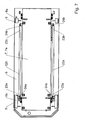
- FIG. 7 is a plan view of the second lifting platform 7b according to FIG. 6 shown.
- the trailing arm 22a, 22b are arranged laterally next to the lifting platform 7b on the right and left sides and parallel to the longitudinal side or lifting platform 7b and for this purpose have a distance approximately the width of the trailing arm 22a, 22b has.
- the articulation points of the trailing arm 22a, 22b are arranged opposite each other via the axles 24a, 24b on the lifting platform 7b and the guide element 9.
- the guide elements 9 have guide surfaces 9a on their mutually facing inner side.
- the present invention is based on a floor-bound transport vehicle for the transport of containers has been described. In principle, it is possible to transport other heavy loads such as slabs, coils in metallurgical, steel and rolling mill technology.
Landscapes
- Engineering & Computer Science (AREA)
- Transportation (AREA)
- Mechanical Engineering (AREA)
- Structural Engineering (AREA)
- Life Sciences & Earth Sciences (AREA)
- Geology (AREA)
- Civil Engineering (AREA)
- Loading Or Unloading Of Vehicles (AREA)
- Platform Screen Doors And Railroad Systems (AREA)
- Control And Other Processes For Unpacking Of Materials (AREA)
- Body Structure For Vehicles (AREA)
- Containers Having Bodies Formed In One Piece (AREA)
- Wrappers (AREA)
Priority Applications (1)
| Application Number | Priority Date | Filing Date | Title |
|---|---|---|---|
| PL07820710T PL2079607T3 (pl) | 2006-10-19 | 2007-09-28 | Podłogowy pojazd transportowy w szczególności do transportu kontenerów |
Applications Claiming Priority (3)
| Application Number | Priority Date | Filing Date | Title |
|---|---|---|---|
| DE102006049372 | 2006-10-19 | ||
| DE200710039778 DE102007039778A1 (de) | 2007-08-23 | 2007-08-23 | Flurgebundenes Transportfahrzeug, insbesondere für den Transport von Containern |
| PCT/EP2007/060323 WO2008046728A1 (de) | 2006-10-19 | 2007-09-28 | Flurgebundenes transportfahrzeug, insbesondere für den transport von containern |
Publications (2)
| Publication Number | Publication Date |
|---|---|
| EP2079607A1 EP2079607A1 (de) | 2009-07-22 |
| EP2079607B1 true EP2079607B1 (de) | 2010-07-07 |
Family
ID=38693352
Family Applications (1)
| Application Number | Title | Priority Date | Filing Date |
|---|---|---|---|
| EP07820710A Not-in-force EP2079607B1 (de) | 2006-10-19 | 2007-09-28 | Flurgebundenes transportfahrzeug, insbesondere für den transport von containern |
Country Status (13)
| Country | Link |
|---|---|
| US (1) | US8128064B2 (pl) |
| EP (1) | EP2079607B1 (pl) |
| JP (1) | JP5231432B2 (pl) |
| KR (1) | KR20090068323A (pl) |
| AT (1) | ATE473130T1 (pl) |
| AU (1) | AU2007312441B2 (pl) |
| CA (1) | CA2666253C (pl) |
| DE (1) | DE502007004347D1 (pl) |
| DK (1) | DK2079607T3 (pl) |
| NZ (1) | NZ575407A (pl) |
| PL (1) | PL2079607T3 (pl) |
| PT (1) | PT2079607E (pl) |
| WO (1) | WO2008046728A1 (pl) |
Cited By (2)
| Publication number | Priority date | Publication date | Assignee | Title |
|---|---|---|---|---|
| DE102010052595A1 (de) * | 2010-11-25 | 2012-07-05 | Powerwind Gmbh | Verfahren zum Errichten einer Windenergieanlage |
| WO2014193541A1 (en) * | 2013-05-31 | 2014-12-04 | The Boeing Company | Cargo container transfer system and method for handling cargo containers |
Families Citing this family (29)
| Publication number | Priority date | Publication date | Assignee | Title |
|---|---|---|---|---|
| DE102007039780A1 (de) * | 2007-08-23 | 2009-02-26 | Gottwald Port Technology Gmbh | Vorrichtung zum Sichern eines Containers auf einer Plattform eines Transportfahrzeugs |
| DE102009025051A1 (de) * | 2009-06-10 | 2010-12-16 | Gottwald Port Technology Gmbh | Flurgebundenes Schwerlast-Transportfahrzeug, insbesondere fahrerloses Schwerlast-Transportfahrzeug für ISO-Container |
| DE102009053235A1 (de) * | 2009-11-06 | 2011-05-19 | Gottwald Port Technology Gmbh | Umschlagsystem für ISO-Container mit einer Containerbrücke |
| DE102010060505A1 (de) | 2010-11-11 | 2012-05-16 | Gottwald Port Technology Gmbh | Containertransportfahrzeug |
| DE102010060504A1 (de) | 2010-11-11 | 2012-05-16 | Gottwald Port Technology Gmbh | System für den Umschlag von Containern |
| CN102756680A (zh) * | 2011-04-27 | 2012-10-31 | 上海宝钢设备检修有限公司 | 有效提高货物运输效率的方法 |
| CN102815546B (zh) * | 2011-06-07 | 2015-04-01 | 上海振华重工(集团)股份有限公司 | 车辆货物托架和车辆货物托架组 |
| ES2728130T3 (es) * | 2011-06-15 | 2019-10-22 | Siemens Gamesa Renewable Energy As | Carro autopropulsado |
| DE102011089858A1 (de) * | 2011-12-23 | 2013-06-27 | Krones Ag | System zum Transport von auf Hilfsmitteln angeordneten Gütern |
| FR3007397B1 (fr) * | 2013-06-24 | 2017-12-01 | Batterie Mobile | Procede de guidage d'un vehicule aeroportuaire |
| FR3007704A1 (fr) * | 2013-06-28 | 2015-01-02 | Batterie Mobile | Vehicule, installation et stations pour le chargement et le dechargement de conteneur |
| DE102013114841A1 (de) * | 2013-12-23 | 2015-06-25 | Terex Mhps Gmbh | Flurgebundenes Transportfahrzeug für Container mit einer Hubfunktion |
| CN104071725B (zh) * | 2014-07-14 | 2016-08-24 | 上海海事大学 | 一种智能化码头电动式集装箱接运平台及接运方法 |
| US11407588B2 (en) | 2015-06-24 | 2022-08-09 | Hds Mercury, Inc. | Multiple degree of freedom mobile robot loader-unloader system and method |
| US11999568B2 (en) | 2015-06-24 | 2024-06-04 | Hds Mercury, Inc. | Mobile robot interactions independent of localization data |
| US11167924B2 (en) | 2015-06-24 | 2021-11-09 | HDS Mercury Inc. | Shelving system and power transfer device |
| WO2016210126A1 (en) | 2015-06-24 | 2016-12-29 | Hds Mercury, Inc. | Mobile robot loader-unloader system and method |
| CN106608595A (zh) | 2015-10-26 | 2017-05-03 | 鹰铁路集装箱物流有限责任公司 | 构造成用于输送各种尺寸的对象的运输器 |
| CN106956940A (zh) | 2015-10-26 | 2017-07-18 | 鹰铁路集装箱物流有限责任公司 | 高架式运输和路线管理系统 |
| DE102015119193A1 (de) | 2015-11-07 | 2017-05-11 | Terex MHPS IP Management GmbH | Batteriemodul für einen Fahrantrieb und Transportfahrzeug hiermit |
| DE102015121846B4 (de) | 2015-12-15 | 2017-07-27 | Terex Mhps Gmbh | Transportfahrzeug für Container |
| DE102015121804B4 (de) * | 2015-12-15 | 2017-07-27 | Terex Mhps Gmbh | Transportfahrzeug für Container |
| US9889787B2 (en) * | 2016-04-19 | 2018-02-13 | Marc S. Thomas | Mobile auxiliary transfer lift caddy |
| EP3458392A1 (en) * | 2016-05-16 | 2019-03-27 | Eaglerail Container Logistics, LLC | Horse and saddle transfer apparatus for shipping containers and method of operation |
| EP3421393A1 (de) * | 2017-06-27 | 2019-01-02 | MLOG Logistics GmbH | Mobiles lagerfahrzeug |
| CN107696938B (zh) * | 2017-08-14 | 2019-07-23 | 武汉理工大学 | 一种可交换式箱体举升装置控制方法 |
| US11338866B2 (en) | 2018-05-31 | 2022-05-24 | Uatc, Llc | Movable front shield for vehicles |
| KR102267936B1 (ko) * | 2019-07-17 | 2021-06-22 | 주식회사 한컴로보틱스 | 안전한 이송을 위한 자동경로차량 |
| US12129122B2 (en) | 2020-05-13 | 2024-10-29 | Hds Mercury, Inc. | Modular inventory handling system and method |
Family Cites Families (22)
| Publication number | Priority date | Publication date | Assignee | Title |
|---|---|---|---|---|
| US472922A (en) * | 1892-04-12 | Device for conveying bricks | ||
| US697070A (en) * | 1901-08-15 | 1902-04-08 | Oliver Colborne | Car-truck. |
| US979898A (en) * | 1910-04-05 | 1910-12-27 | Clarence M Steele | Brick-car. |
| US2043887A (en) * | 1935-05-16 | 1936-06-09 | John L Dement | Furniture truck |
| US2438571A (en) * | 1944-05-27 | 1948-03-30 | Jr Glenway Maxon | Stabilizer for spring mounted vehicles |
| US2449863A (en) * | 1945-03-31 | 1948-09-21 | Weaver Mfg Co | Load lifting appliance |
| US2940767A (en) * | 1955-10-04 | 1960-06-14 | Yale & Towne Mfg Co | Light duty hydraulic truck |
| US2993703A (en) * | 1956-12-31 | 1961-07-25 | Barrett Cravens Co | Lift truck |
| US3214136A (en) * | 1963-10-01 | 1965-10-26 | Eldon A Marks | Elevating mechanism for trailers |
| US3266774A (en) * | 1964-08-03 | 1966-08-16 | Clark Equipment Co | Lifting mechanism |
| US3319932A (en) | 1965-09-03 | 1967-05-16 | Dorr Oliver Inc | Pallet trailer having a toggle-operated platform tiltable about one or more axes |
| US3497092A (en) * | 1967-09-22 | 1970-02-24 | Skagit Corp | Pre-load transport system |
| JPS5354008Y2 (pl) * | 1974-05-14 | 1978-12-23 | ||
| SE434255B (sv) * | 1982-05-19 | 1984-07-16 | Kalmar Lagab Ab | Anordning vid en lastberare samt en anordning for overforing av lastberaren fran en jernvegsvagn till en lastbil och omvent |
| DE3328705A1 (de) * | 1983-08-09 | 1985-04-25 | Aluminium-Walzwerke Singen Gmbh, 7700 Singen | Transportfahrzeug |
| US4792272A (en) | 1986-05-23 | 1988-12-20 | Standard Manufacturing Company, Inc. | Container handling apparatus |
| NL8701823A (nl) | 1987-08-03 | 1989-03-01 | Europ Container Terminus | Op- en overslagsysteem voor containers. |
| JPH01128435U (pl) * | 1988-02-26 | 1989-09-01 | ||
| DE4138512A1 (de) * | 1991-11-23 | 1993-05-27 | Rolf Dipl Ing Kanzmeier | Abrollkippfahrzeug mit hakenaufnahme |
| US5525019A (en) | 1994-11-23 | 1996-06-11 | Lantis Corporation | Rear platform lift |
| JPH092275A (ja) * | 1995-06-23 | 1997-01-07 | Hitachi Ltd | リフト機能付き電動運搬車 |
| JPH10129329A (ja) * | 1996-11-05 | 1998-05-19 | Toyo Umpanki Co Ltd | 運搬車両 |
-
2007
- 2007-09-28 EP EP07820710A patent/EP2079607B1/de not_active Not-in-force
- 2007-09-28 NZ NZ575407A patent/NZ575407A/en not_active IP Right Cessation
- 2007-09-28 US US12/443,865 patent/US8128064B2/en not_active Expired - Fee Related
- 2007-09-28 AT AT07820710T patent/ATE473130T1/de active
- 2007-09-28 AU AU2007312441A patent/AU2007312441B2/en not_active Ceased
- 2007-09-28 DE DE502007004347T patent/DE502007004347D1/de active Active
- 2007-09-28 JP JP2009532756A patent/JP5231432B2/ja not_active Expired - Fee Related
- 2007-09-28 PL PL07820710T patent/PL2079607T3/pl unknown
- 2007-09-28 KR KR1020097006660A patent/KR20090068323A/ko not_active Abandoned
- 2007-09-28 PT PT07820710T patent/PT2079607E/pt unknown
- 2007-09-28 CA CA2666253A patent/CA2666253C/en not_active Expired - Fee Related
- 2007-09-28 DK DK07820710.7T patent/DK2079607T3/da active
- 2007-09-28 WO PCT/EP2007/060323 patent/WO2008046728A1/de not_active Ceased
Cited By (2)
| Publication number | Priority date | Publication date | Assignee | Title |
|---|---|---|---|---|
| DE102010052595A1 (de) * | 2010-11-25 | 2012-07-05 | Powerwind Gmbh | Verfahren zum Errichten einer Windenergieanlage |
| WO2014193541A1 (en) * | 2013-05-31 | 2014-12-04 | The Boeing Company | Cargo container transfer system and method for handling cargo containers |
Also Published As
| Publication number | Publication date |
|---|---|
| JP5231432B2 (ja) | 2013-07-10 |
| US8128064B2 (en) | 2012-03-06 |
| PT2079607E (pt) | 2010-09-23 |
| ATE473130T1 (de) | 2010-07-15 |
| DE502007004347D1 (de) | 2010-08-19 |
| CA2666253A1 (en) | 2008-04-24 |
| NZ575407A (en) | 2011-02-25 |
| AU2007312441B2 (en) | 2012-02-02 |
| DK2079607T3 (da) | 2010-10-25 |
| AU2007312441A1 (en) | 2008-04-24 |
| US20100213430A1 (en) | 2010-08-26 |
| JP2010506785A (ja) | 2010-03-04 |
| KR20090068323A (ko) | 2009-06-26 |
| CA2666253C (en) | 2015-01-20 |
| EP2079607A1 (de) | 2009-07-22 |
| PL2079607T3 (pl) | 2010-12-31 |
| WO2008046728A1 (de) | 2008-04-24 |
Similar Documents
| Publication | Publication Date | Title |
|---|---|---|
| WO2008046728A1 (de) | Flurgebundenes transportfahrzeug, insbesondere für den transport von containern | |
| EP3268257B1 (de) | Hebbare tragvorrichtung | |
| DE102012004292A1 (de) | Hubvorrichtung sowie Güterumschlagvorrichtung und Güterumschlagverfahren mit einer derartigen Hubvorrichtung | |
| DE102007039778A1 (de) | Flurgebundenes Transportfahrzeug, insbesondere für den Transport von Containern | |
| DE1807061A1 (de) | Fahrzeug zum Handhaben grossvolumiger Behaelter,wie Container | |
| EP3086978A1 (de) | Flurgebundenes transportfahrzeug für container mit einer hubfunktion | |
| DE102019116809B4 (de) | Transportfahrzeug, Verfahren zum Aufnehmen einer Last durch ein Transportfahrzeug und System mit einem Transportfahrzeug und einer Last | |
| DE69020545T2 (de) | Schienentransportwagen für Nutzfahrzeuge. | |
| EP0645293B1 (de) | Güterwagen zur Bildung eines schienengebundenen Güterzuges für den kombinierten Güterverkehr Schiene/Strasse | |
| DE69730326T2 (de) | Portalhubwagen | |
| EP3000696B1 (de) | Kupplungsvorrichtung, System mit einer solchen Kupplungsvorrichtung und Verwendung einer solchen Kupplungsvorrichtung | |
| EP3326892A1 (de) | Transportanhänger mit einem fahrwerk und mindestens einer bodenplattform | |
| CH629446A5 (en) | Device for transferring transported goods | |
| EP0328878A2 (de) | Nutzfahrzeug zum Transport von Containern | |
| DE19512246C2 (de) | Selbstfahrendes und auf ein Transportfahrzeug selbstauf- und selbstabladbares Verladesystem für Container oder Wechselbrücken | |
| DE3822542A1 (de) | Ladeanhaenger | |
| DE2755223A1 (de) | Einrichtung zum umsetzen von transportguetern | |
| DE19938727A1 (de) | Hebe- und Ladevorrichtung | |
| WO2013167315A1 (de) | Hubvorrichtung sowie güterumschlagvorrichtung und güterumschlagverfahren mit zumindest einer derartigen hubvorrichtung | |
| DE3213421C2 (pl) | ||
| EP3785988A1 (de) | Fahrzeugtransporter | |
| EP3604072A1 (de) | Hebbare tragvorrichtung | |
| AT401911B (de) | Transportwaggon, insbesondere niederflurwagen | |
| DE3431561A1 (de) | Nutzfahrzeug mit kombinierter verladeeinrichtung | |
| WO2016162508A1 (de) | System zur aufnahme von gegenständen |
Legal Events
| Date | Code | Title | Description |
|---|---|---|---|
| PUAI | Public reference made under article 153(3) epc to a published international application that has entered the european phase |
Free format text: ORIGINAL CODE: 0009012 |
|
| 17P | Request for examination filed |
Effective date: 20090422 |
|
| AK | Designated contracting states |
Kind code of ref document: A1 Designated state(s): AT BE BG CH CY CZ DE DK EE ES FI FR GB GR HU IE IS IT LI LT LU LV MC MT NL PL PT RO SE SI SK TR |
|
| 17Q | First examination report despatched |
Effective date: 20100201 |
|
| GRAP | Despatch of communication of intention to grant a patent |
Free format text: ORIGINAL CODE: EPIDOSNIGR1 |
|
| DAX | Request for extension of the european patent (deleted) | ||
| GRAS | Grant fee paid |
Free format text: ORIGINAL CODE: EPIDOSNIGR3 |
|
| GRAA | (expected) grant |
Free format text: ORIGINAL CODE: 0009210 |
|
| AK | Designated contracting states |
Kind code of ref document: B1 Designated state(s): AT BE BG CH CY CZ DE DK EE ES FI FR GB GR HU IE IS IT LI LT LU LV MC MT NL PL PT RO SE SI SK TR |
|
| REG | Reference to a national code |
Ref country code: GB Ref legal event code: FG4D Free format text: NOT ENGLISH |
|
| REG | Reference to a national code |
Ref country code: CH Ref legal event code: EP |
|
| REG | Reference to a national code |
Ref country code: IE Ref legal event code: FG4D |
|
| REF | Corresponds to: |
Ref document number: 502007004347 Country of ref document: DE Date of ref document: 20100819 Kind code of ref document: P |
|
| REG | Reference to a national code |
Ref country code: CH Ref legal event code: NV Representative=s name: ALDO ROEMPLER PATENTANWALT |
|
| REG | Reference to a national code |
Ref country code: SE Ref legal event code: TRGR |
|
| REG | Reference to a national code |
Ref country code: GR Ref legal event code: EP Ref document number: 20100401732 Country of ref document: GR |
|
| REG | Reference to a national code |
Ref country code: PT Ref legal event code: SC4A Free format text: AVAILABILITY OF NATIONAL TRANSLATION Effective date: 20100916 |
|
| REG | Reference to a national code |
Ref country code: NL Ref legal event code: T3 |
|
| REG | Reference to a national code |
Ref country code: DK Ref legal event code: T3 |
|
| PG25 | Lapsed in a contracting state [announced via postgrant information from national office to epo] |
Ref country code: SI Free format text: LAPSE BECAUSE OF FAILURE TO SUBMIT A TRANSLATION OF THE DESCRIPTION OR TO PAY THE FEE WITHIN THE PRESCRIBED TIME-LIMIT Effective date: 20100707 |
|
| LTIE | Lt: invalidation of european patent or patent extension |
Effective date: 20100707 |
|
| REG | Reference to a national code |
Ref country code: PL Ref legal event code: T3 |
|
| PG25 | Lapsed in a contracting state [announced via postgrant information from national office to epo] |
Ref country code: LT Free format text: LAPSE BECAUSE OF FAILURE TO SUBMIT A TRANSLATION OF THE DESCRIPTION OR TO PAY THE FEE WITHIN THE PRESCRIBED TIME-LIMIT Effective date: 20100707 |
|
| PG25 | Lapsed in a contracting state [announced via postgrant information from national office to epo] |
Ref country code: BG Free format text: LAPSE BECAUSE OF FAILURE TO SUBMIT A TRANSLATION OF THE DESCRIPTION OR TO PAY THE FEE WITHIN THE PRESCRIBED TIME-LIMIT Effective date: 20101007 Ref country code: CY Free format text: LAPSE BECAUSE OF FAILURE TO SUBMIT A TRANSLATION OF THE DESCRIPTION OR TO PAY THE FEE WITHIN THE PRESCRIBED TIME-LIMIT Effective date: 20100707 Ref country code: IS Free format text: LAPSE BECAUSE OF FAILURE TO SUBMIT A TRANSLATION OF THE DESCRIPTION OR TO PAY THE FEE WITHIN THE PRESCRIBED TIME-LIMIT Effective date: 20101107 |
|
| PG25 | Lapsed in a contracting state [announced via postgrant information from national office to epo] |
Ref country code: LV Free format text: LAPSE BECAUSE OF FAILURE TO SUBMIT A TRANSLATION OF THE DESCRIPTION OR TO PAY THE FEE WITHIN THE PRESCRIBED TIME-LIMIT Effective date: 20100707 |
|
| PG25 | Lapsed in a contracting state [announced via postgrant information from national office to epo] |
Ref country code: MC Free format text: LAPSE BECAUSE OF NON-PAYMENT OF DUE FEES Effective date: 20100930 |
|
| PLBE | No opposition filed within time limit |
Free format text: ORIGINAL CODE: 0009261 |
|
| STAA | Information on the status of an ep patent application or granted ep patent |
Free format text: STATUS: NO OPPOSITION FILED WITHIN TIME LIMIT |
|
| PG25 | Lapsed in a contracting state [announced via postgrant information from national office to epo] |
Ref country code: SK Free format text: LAPSE BECAUSE OF FAILURE TO SUBMIT A TRANSLATION OF THE DESCRIPTION OR TO PAY THE FEE WITHIN THE PRESCRIBED TIME-LIMIT Effective date: 20100707 Ref country code: CZ Free format text: LAPSE BECAUSE OF FAILURE TO SUBMIT A TRANSLATION OF THE DESCRIPTION OR TO PAY THE FEE WITHIN THE PRESCRIBED TIME-LIMIT Effective date: 20100707 Ref country code: EE Free format text: LAPSE BECAUSE OF FAILURE TO SUBMIT A TRANSLATION OF THE DESCRIPTION OR TO PAY THE FEE WITHIN THE PRESCRIBED TIME-LIMIT Effective date: 20100707 Ref country code: RO Free format text: LAPSE BECAUSE OF FAILURE TO SUBMIT A TRANSLATION OF THE DESCRIPTION OR TO PAY THE FEE WITHIN THE PRESCRIBED TIME-LIMIT Effective date: 20100707 |
|
| 26N | No opposition filed |
Effective date: 20110408 |
|
| REG | Reference to a national code |
Ref country code: DE Ref legal event code: R097 Ref document number: 502007004347 Country of ref document: DE Effective date: 20110408 |
|
| PG25 | Lapsed in a contracting state [announced via postgrant information from national office to epo] |
Ref country code: MT Free format text: LAPSE BECAUSE OF FAILURE TO SUBMIT A TRANSLATION OF THE DESCRIPTION OR TO PAY THE FEE WITHIN THE PRESCRIBED TIME-LIMIT Effective date: 20100707 |
|
| PG25 | Lapsed in a contracting state [announced via postgrant information from national office to epo] |
Ref country code: HU Free format text: LAPSE BECAUSE OF FAILURE TO SUBMIT A TRANSLATION OF THE DESCRIPTION OR TO PAY THE FEE WITHIN THE PRESCRIBED TIME-LIMIT Effective date: 20110108 Ref country code: LU Free format text: LAPSE BECAUSE OF NON-PAYMENT OF DUE FEES Effective date: 20100928 |
|
| PG25 | Lapsed in a contracting state [announced via postgrant information from national office to epo] |
Ref country code: TR Free format text: LAPSE BECAUSE OF FAILURE TO SUBMIT A TRANSLATION OF THE DESCRIPTION OR TO PAY THE FEE WITHIN THE PRESCRIBED TIME-LIMIT Effective date: 20100707 |
|
| PGFP | Annual fee paid to national office [announced via postgrant information from national office to epo] |
Ref country code: FI Payment date: 20140911 Year of fee payment: 8 Ref country code: DE Payment date: 20140922 Year of fee payment: 8 Ref country code: GR Payment date: 20140919 Year of fee payment: 8 Ref country code: DK Payment date: 20140919 Year of fee payment: 8 Ref country code: CH Payment date: 20140919 Year of fee payment: 8 Ref country code: IE Payment date: 20140918 Year of fee payment: 8 |
|
| PGFP | Annual fee paid to national office [announced via postgrant information from national office to epo] |
Ref country code: AT Payment date: 20140911 Year of fee payment: 8 Ref country code: SE Payment date: 20140918 Year of fee payment: 8 Ref country code: FR Payment date: 20140919 Year of fee payment: 8 Ref country code: ES Payment date: 20140926 Year of fee payment: 8 Ref country code: GB Payment date: 20140919 Year of fee payment: 8 Ref country code: PL Payment date: 20140820 Year of fee payment: 8 |
|
| PGFP | Annual fee paid to national office [announced via postgrant information from national office to epo] |
Ref country code: IT Payment date: 20140923 Year of fee payment: 8 Ref country code: PT Payment date: 20140331 Year of fee payment: 8 |
|
| PGFP | Annual fee paid to national office [announced via postgrant information from national office to epo] |
Ref country code: NL Payment date: 20140918 Year of fee payment: 8 |
|
| PGFP | Annual fee paid to national office [announced via postgrant information from national office to epo] |
Ref country code: BE Payment date: 20140919 Year of fee payment: 8 |
|
| REG | Reference to a national code |
Ref country code: PT Ref legal event code: MM4A Free format text: LAPSE DUE TO NON-PAYMENT OF FEES Effective date: 20160328 Ref country code: DE Ref legal event code: R119 Ref document number: 502007004347 Country of ref document: DE |
|
| REG | Reference to a national code |
Ref country code: DK Ref legal event code: EBP Effective date: 20150930 |
|
| PG25 | Lapsed in a contracting state [announced via postgrant information from national office to epo] |
Ref country code: IT Free format text: LAPSE BECAUSE OF NON-PAYMENT OF DUE FEES Effective date: 20150928 |
|
| REG | Reference to a national code |
Ref country code: CH Ref legal event code: PL |
|
| REG | Reference to a national code |
Ref country code: SE Ref legal event code: EUG |
|
| REG | Reference to a national code |
Ref country code: AT Ref legal event code: MM01 Ref document number: 473130 Country of ref document: AT Kind code of ref document: T Effective date: 20150928 |
|
| GBPC | Gb: european patent ceased through non-payment of renewal fee |
Effective date: 20150928 |
|
| PG25 | Lapsed in a contracting state [announced via postgrant information from national office to epo] |
Ref country code: FI Free format text: LAPSE BECAUSE OF NON-PAYMENT OF DUE FEES Effective date: 20150928 Ref country code: PT Free format text: LAPSE BECAUSE OF NON-PAYMENT OF DUE FEES Effective date: 20160328 Ref country code: SE Free format text: LAPSE BECAUSE OF NON-PAYMENT OF DUE FEES Effective date: 20150929 |
|
| REG | Reference to a national code |
Ref country code: NL Ref legal event code: MM Effective date: 20151001 |
|
| REG | Reference to a national code |
Ref country code: GR Ref legal event code: ML Ref document number: 20100401732 Country of ref document: GR Effective date: 20160405 |
|
| REG | Reference to a national code |
Ref country code: IE Ref legal event code: MM4A |
|
| REG | Reference to a national code |
Ref country code: FR Ref legal event code: ST Effective date: 20160531 |
|
| PG25 | Lapsed in a contracting state [announced via postgrant information from national office to epo] |
Ref country code: DE Free format text: LAPSE BECAUSE OF NON-PAYMENT OF DUE FEES Effective date: 20160401 Ref country code: GB Free format text: LAPSE BECAUSE OF NON-PAYMENT OF DUE FEES Effective date: 20150928 Ref country code: GR Free format text: LAPSE BECAUSE OF NON-PAYMENT OF DUE FEES Effective date: 20160405 Ref country code: CH Free format text: LAPSE BECAUSE OF NON-PAYMENT OF DUE FEES Effective date: 20150930 Ref country code: IE Free format text: LAPSE BECAUSE OF NON-PAYMENT OF DUE FEES Effective date: 20150928 Ref country code: LI Free format text: LAPSE BECAUSE OF NON-PAYMENT OF DUE FEES Effective date: 20150930 |
|
| PG25 | Lapsed in a contracting state [announced via postgrant information from national office to epo] |
Ref country code: FR Free format text: LAPSE BECAUSE OF NON-PAYMENT OF DUE FEES Effective date: 20150930 Ref country code: AT Free format text: LAPSE BECAUSE OF NON-PAYMENT OF DUE FEES Effective date: 20150928 Ref country code: NL Free format text: LAPSE BECAUSE OF NON-PAYMENT OF DUE FEES Effective date: 20151001 |
|
| PG25 | Lapsed in a contracting state [announced via postgrant information from national office to epo] |
Ref country code: DK Free format text: LAPSE BECAUSE OF NON-PAYMENT OF DUE FEES Effective date: 20150930 |
|
| REG | Reference to a national code |
Ref country code: ES Ref legal event code: FD2A Effective date: 20161201 |
|
| PG25 | Lapsed in a contracting state [announced via postgrant information from national office to epo] |
Ref country code: ES Free format text: LAPSE BECAUSE OF NON-PAYMENT OF DUE FEES Effective date: 20150929 Ref country code: PL Free format text: LAPSE BECAUSE OF NON-PAYMENT OF DUE FEES Effective date: 20150928 |
|
| PG25 | Lapsed in a contracting state [announced via postgrant information from national office to epo] |
Ref country code: BE Free format text: LAPSE BECAUSE OF NON-PAYMENT OF DUE FEES Effective date: 20150930 |