EP2079919B1 - Kurbelwellen- und verbrennungsmotoreinheit - Google Patents
Kurbelwellen- und verbrennungsmotoreinheit Download PDFInfo
- Publication number
- EP2079919B1 EP2079919B1 EP06812996.4A EP06812996A EP2079919B1 EP 2079919 B1 EP2079919 B1 EP 2079919B1 EP 06812996 A EP06812996 A EP 06812996A EP 2079919 B1 EP2079919 B1 EP 2079919B1
- Authority
- EP
- European Patent Office
- Prior art keywords
- crankcase
- combustion engine
- fan
- carburettor
- engine unit
- Prior art date
- Legal status (The legal status is an assumption and is not a legal conclusion. Google has not performed a legal analysis and makes no representation as to the accuracy of the status listed.)
- Active
Links
- 238000002485 combustion reaction Methods 0.000 title claims description 21
- 238000001816 cooling Methods 0.000 claims description 36
- 244000025254 Cannabis sativa Species 0.000 claims description 2
- 230000002000 scavenging effect Effects 0.000 claims description 2
- 239000003570 air Substances 0.000 description 24
- 238000010438 heat treatment Methods 0.000 description 7
- 238000013021 overheating Methods 0.000 description 3
- 239000000446 fuel Substances 0.000 description 2
- 238000007373 indentation Methods 0.000 description 2
- 230000005855 radiation Effects 0.000 description 2
- 239000012080 ambient air Substances 0.000 description 1
- 230000005540 biological transmission Effects 0.000 description 1
- 230000015572 biosynthetic process Effects 0.000 description 1
- 230000001419 dependent effect Effects 0.000 description 1
- 239000000203 mixture Substances 0.000 description 1
- 238000000465 moulding Methods 0.000 description 1
Images


Classifications
-
- F—MECHANICAL ENGINEERING; LIGHTING; HEATING; WEAPONS; BLASTING
- F02—COMBUSTION ENGINES; HOT-GAS OR COMBUSTION-PRODUCT ENGINE PLANTS
- F02F—CYLINDERS, PISTONS OR CASINGS, FOR COMBUSTION ENGINES; ARRANGEMENTS OF SEALINGS IN COMBUSTION ENGINES
- F02F7/00—Casings, e.g. crankcases
- F02F7/0065—Shape of casings for other machine parts and purposes, e.g. utilisation purposes, safety
- F02F7/007—Adaptations for cooling
-
- F—MECHANICAL ENGINEERING; LIGHTING; HEATING; WEAPONS; BLASTING
- F01—MACHINES OR ENGINES IN GENERAL; ENGINE PLANTS IN GENERAL; STEAM ENGINES
- F01P—COOLING OF MACHINES OR ENGINES IN GENERAL; COOLING OF INTERNAL-COMBUSTION ENGINES
- F01P5/00—Pumping cooling-air or liquid coolants
- F01P5/02—Pumping cooling-air; Arrangements of cooling-air pumps, e.g. fans or blowers
- F01P5/06—Guiding or ducting air to, or from, ducted fans
-
- F—MECHANICAL ENGINEERING; LIGHTING; HEATING; WEAPONS; BLASTING
- F02—COMBUSTION ENGINES; HOT-GAS OR COMBUSTION-PRODUCT ENGINE PLANTS
- F02B—INTERNAL-COMBUSTION PISTON ENGINES; COMBUSTION ENGINES IN GENERAL
- F02B63/00—Adaptations of engines for driving pumps, hand-held tools or electric generators; Portable combinations of engines with engine-driven devices
- F02B63/02—Adaptations of engines for driving pumps, hand-held tools or electric generators; Portable combinations of engines with engine-driven devices for hand-held tools
Definitions
- the invention relates to an air-cooled combustion engine unit for a hand-held working machine, such as a brushcutter or a trimmer comprising at least one engine cylinder, a crankcase a carburettor and a muffler.
- the crankcase comprises a crankcase chamber, a fan wheel side with a fan scroll and a fan wheel with fan blades arranged in the fan scroll, a clutch side opposite the fan wheel side and, between the fan wheel side and the clutch side. It further comprises a number of crankcase walls, a cylinder connection side with opening for at least a connecting rod, and a carburettor side.
- the invention also relates to a handheld working machine, for example a brushcutter or a trimmer, with a rotating working tool, for example a saw blade, for clearing of smaller trees, bushes, brush or grass.
- crankcase chamber and the crankcase walls of conventionally designed crankcases for combustion engines are significantly heated during engine operation.
- This can imply problems.
- the main bearings i.e. the crankshaft bearings that are arranged inside the crankcase chamber
- can overheat particularly the main bearing on the clutch side runs the risk of overheating
- partly the carburettor can overheat through heat radiation from the crankcase side that is facing the carburettor. Heating of the carburettor from the crankcase can become particularly troublesome during a break, e.g. due to refuelling or any other reason, when the engine's fan wheel is at a standstill and therefore no cooling-air circulation takes place.
- Heating of the carburettor due to such after-heating can result in formation of fuel vapour bubbles in the carburettor. In turn, this can result in that the engine becomes difficult or impossible to restart without a long period of cooling, which constitutes a serious inconvenience.
- Combustion engine units in modern brushcutters and trimmers are examples of working machines where this type of problem can appear.
- the engine unit is characterised in that, the engine is a two-stroke engine of the crankcase scavenging type, i.e. that at least the combustion air for the engine flows through its crankcase and in that, through a crankcase wall on at least said carburettor side between the fan wheel side and the clutch side, one or more cooling ducts extends between one or more inlet openings for cooling air in the fan scroll and one or more outlet openings for the cooling air exiting in a clutch housing, for cooling of the wall on said carburettor side between the fan wheel side and the clutch side.
- the fan wheel can, but needs necessarily not, be integrated in a flywheel.
- a separate flywheel can for instance be arranged on the clutch side.
- a crankcase according to the preferred embodiment of the invention is generally designated 1 in the drawing figures.
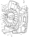
- a fan wheel side 2 shown as a frontal view in Fig. 1 , there is a fan wheel 3 in a fan scroll 4, Fig.2 .
- the fan wheel 3 is in a conventional way provided with fan blades 5 and forms together with the fan scroll a centrifugal fan, that is driving cooling air out through an outlet section 6 in the fan scroll 4 for cooling of primarily an engine cylinder 8 (schematically shown in Fig. 1 ), that is an integral part of a combustion engine.
- the fan wheel 3 is, when the engine is running, rotated by a crankshaft 10, that extends through the crankcase 1.
- clutch side 11 Fig. 5
- the not shown centrifugal clutch is, when assembled, arranged in a clutch housing 12, that, when assembled, normally is covered by a not shown clutch cover.
- crankcase 1 forms a part of a combustion engine unit, generally designated 14 in Fig. 1 .
- unit 14 includes, apart from crankcase 1 and cylinder 8, also a carburettor 15 or other arrangement for supply of air/fuel mixture to the cylinder 8 and a muffler 16.
- Cylinder 8 is connected to crankcase 1 on one of the sides of the crankcase between the fan wheel side 2 and the clutch side 11, here designated cylinder connection side 17. Two other sides are designated; carburettor side 18, on which the carburettor 15 is connected and muffler side 19, on which side the muffler 16 is arranged at a short distance from the crankcase.
- a crankcase chamber is designated 20.
- the crankshaft 10 is suspended in the crankcase chamber 20 by means of two main bearings, namely a first main bearing 23 fitted in a crankcase gable 25 on the clutch side 11 and a second main bearing 24 fitted in an opposite crankcase gable 26 on the fan wheel side 2.
- the main bearings 23 and 24, and in particular the first main bearing 23, constitute critical elements in the crankcase design due to the risk of overheating.
- Crankcase 1 consists of two halves 1A and IB, Fig. 6 . Both halves 1A and IB, that are separately cast, are joined together to one unit by means of a screw fasteners and are in contact with each other in a contact plane 1C.
- crankcase 1 has double walls in the area of the crankcase chamber 20 on the carburettor side 18, Fig. 6 .
- An inner wall is designated 30 and an outer wall is designated 31.
- a cooling air duct 32 that extends outside the crankcase chamber 20 within the area of at least essentially the entire part of the carburettor side 18 that is exposed towards the carburettor 15, i.e. that corresponds to the extent of the carburettor.
- this area has been indicated by broken lines and designated 33.
- the inner and outer walls of the antechamber 36 are designated 37 and 38 respectively.
- the inner wall 37 forms an extension of the inner wall 30 of channel 32.
- An inlet opening 41 in the cover 40 is directed against the direction of air flow in the outlet section 6.
- the plane of the inlet opening 41, Fig 3 can be, but need not be, essentially perpendicular to the bottom wall of fan scroll 4 in the area of outlet section 6.
- a couple of side walls extend backwards, curved so that one side 42 connects to the fan wheel's 3 circular curvature and so that the opposite side 43 connects to the widening curvature of the outlet section.
- the roof 44 of the air inlet cover 40 is initially almost plane and is then curving down towards the bottom wall of outlet section 6.
- On the roof of the air inlet cover 40 there is a flange 46, that continuously extends in a curvature backwards in the outlet section 6 behind the cover.
- the cover 40 is bolted in the bottom wall of the outlet section 6.
- a screw hole in the wall and a seat 45 for the screw head is shown in Fig. 3 .
- the cooling air duct 32 is provided with an outlet opening 50 in the crankcase gable 25 on the clutch side, Fig. 4 and Fig. 6 .
- an evacuation opening 51 is arranged for guiding the cooling air away from the housing 12 on the clutch side, that is covered by the not shown centrifugal clutch, within which area 12 also the outlet opening 50 of the cooling air duct 32 is located.
- the described unit 14 and the arrangement work in the following manner.
- the fan wheel 3 is driven by the crankshaft 10.
- the crankcase chamber 20, including its walls and bearings 23, 24, is heated mainly due to the chamber's communication with the cylinder 8.
- the inner and outer crankcase walls 30 and 31 respectively are cooled by the cooling air pushed by the fan blades 5 into the cover 40 and further via the antechamber 36 into the cooling air duct 32, that prevents its walls 30, 31 from heating up to a disturbingly high temperature.
- only a sub-flow of the air that is set into motion by the fan blades 5 of the fan wheel is driven into the cover 40 and further through the chamber 36 and cooling air duct 32.
- the main flow is blown out through the mouth of the outlet section 6 in order to cool the outside of cylinder 8 in a normal manner.
- the arc-shaped flange 46 on the roof of the cover and behind the cover 40 is thus contributing to direct the airflow and create desired fan operation in the outlet section for cooling of the cylinder 8.
- the diverted cooling air flows out through opening 50 in the clutch housing 12 and contributes to cool the centrifugal clutch under the not shown clutch cover and finally leaves the clutch housing 12 through the evacuation opening 51 to be spread into the ambient air.
- the cooling of the inner wall 30 on the carburettor side contributes to keep the temperature of the crankcase chamber 20 at a moderately high level, with the intent to prevent the main bearings 23 and 24 from overheating.
- the outer wall 31 in the area of the crankcase chamber 20 has however been continuously cooled by means of cooling air that flows through the cooling air duct 32, which prevents or at least strongly counteracts the heating of the carburettor due to the after-heat from the crankcase while the engine and consequently the fan wheel and its fan blades are at a standstill.
- the inner wall 30 in the area of the cooling air duct 32 has also been cooled during the operation of the machine, which also counteracts damage particularly to the main bearings 23, 24 due to after-heating during short operational interruptions.
Landscapes
- Engineering & Computer Science (AREA)
- Chemical & Material Sciences (AREA)
- Combustion & Propulsion (AREA)
- Mechanical Engineering (AREA)
- General Engineering & Computer Science (AREA)
- Structures Of Non-Positive Displacement Pumps (AREA)
- Cylinder Crankcases Of Internal Combustion Engines (AREA)
Claims (10)
- Luftgekühlte Verbrennungsmotoreinheit für eine handgeführte Arbeitsmaschine wie einen Gestrüppschneider oder einen Trimmer, die mindestens einen Motorzylinder (8), ein Kurbelgehäuse (1), einen Vergaser (15) und einen Schalldämpfer (16) umfasst, wobei das Kurbelgehäuse (1) eine Kurbelgehäusekammer (20), eine Gebläseradseite (2) mit einer Gebläsespirale (4) und ein Gebläserad (3) mit in der Gebläsespirale (4) angeordneten Gebläseflügeln (5), eine Kupplungsseite (11) gegenüber der Gebläseradseite (2) und, zwischen der Gebläseradseite (2) und der Kupplungsseite (11), eine Anzahl von Kurbelgehäusewänden, eine Zylinderanschlussseite (17) mit einer Öffnung für mindestens eine Kolbenstange (21) und eine Vergaserseite (18) umfasst, dadurch gekennzeichnet, dass der Motor ein Zweitaktmotor mit Kurbelgehäusespülung ist, das heißt, dass mindestens die Verbrennungsluft für den Motor durch sein Kurbelgehäuse strömt, und dadurch, dass durch eine Kurbelgehäusewand auf mindestens der Vergaserseite (18) zwischen der Gebläseradseite (2) und der Kupplungsseite (11) sich ein oder mehrere Kühlkanäle (32) zwischen einer oder mehreren Einlassöffnungen (35) für Kühlluft in der Gebläsespirale (4) und eine oder mehrere Auslassöffnungen (50) für die in ein Kupplungsgehäuse (12) austretende Kühlluft zum Kühlen der Wand auf der Vergaserseite (18) zwischen der Gebläseradseite (2) und der Kupplungsseite (11) erstrecken.
- Verbrennungsmotoreinheit nach Anspruch 1, dadurch gekennzeichnet, dass die Kurbelgehäusewand (30, 31) auf der Vergaserseite Doppelwände aufweist, die eine innere Wand (30), die in Richtung einer Kurbelgehäusekammer (20) ausgerichtet ist, und eine äußere Wand (31) umfassen, wobei ein Raum zwischen den Wänden (30, 31) einen spaltförmigen Kühlkanal (32) bildet.
- Verbrennungsmotoreinheit nach Anspruch 1 oder 2, dadurch gekennzeichnet, dass die eine oder mehreren Einlassöffnungen (35) für Kühlluft in der Gebläsespirale von einer Einlassabdeckung (40) für Kühlluft zum Umleiten eines Teilstroms der Luft abgedeckt sind, die von dem Gebläserad durch den Auslassabschnitt der Gebläsespirale geblasen wird.
- Verbrennungsmotoreinheit nach Anspruch 3, dadurch gekennzeichnet, dass die Einlassabdeckung in dem Auslassabschnitt (6) der Gebläsespirale angeordnet ist.
- Verbrennungsmotoreinheit nach Anspruch 4, dadurch gekennzeichnet, dass der Mund der Einlassabdeckung in Relation zu dem Boden der Gebläsespirale in dem Bereich des Auslassabschnitts (6) im Wesentlichen quer positioniert ist.
- Verbrennungsmotoreinheit nach einem der Ansprüche 1-5, dadurch gekennzeichnet, dass eine Evakuierungsöffnung (51) an dem Boden des Kupplungsgehäuses (12) in einem Abstand von der einen oder den mehreren Auslassöffnungen (50) für die Kühlluft zum Evakuieren der verbrauchten Kühlluft aus dem Kupplungsgehäuse angeordnet ist.
- Verbrennungsmotoreinheit nach den Ansprüchen 1-2, dadurch gekennzeichnet, dass sich der Kühlluftkanal (32) außerhalb der Kurbelgehäusekammer (20) innerhalb des Bereichs des gesamten Teils der Vergaserseite (18), die in Richtung des Vergasers freiliegt, erstreckt.
- Verbrennungsmotoreinheit nach einem der Ansprüche 1-7, dadurch gekennzeichnet, dass sich ein oder mehrere Kühlkanäle in der Kurbelgehäusewand entlang eines Bereichs (33) der Kurbelgehäusewand erstrecken, der mindestens einem signifikanten Teil des Ausmaßes des Vergasers entspricht.
- Verbrennungsmotoreinheit nach einem der Ansprüche 1-8, dadurch gekennzeichnet, dass ein Teilstrom der Luft, die von dem Gebläserad durch den Auslassabschnitt (6) der Gebläsespirale geblasen wird, zu dem einen oder den mehreren Kühlkanälen umgeleitet wird, während die übrige Luft durch den Auslassabschnitt zum Kühlen des Motorzylinders herausgeblasen wird.
- Handgeführte Arbeitsmaschine wie ein Gestrüppschneider oder Trimmer, die ein drehendes Arbeitswerkzeug, beispielsweise ein Sägeblatt, zum Roden von kleineren Bäumen, Büschen, Gestrüpp und/oder Gras umfasst, dadurch gekennzeichnet, dass das drehende Arbeitswerkzeug durch eine Verbrennungsmotoreinheit nach einem der Ansprüche 1-9 angetrieben wird.
Applications Claiming Priority (1)
| Application Number | Priority Date | Filing Date | Title |
|---|---|---|---|
| PCT/SE2006/001273 WO2008057015A1 (en) | 2006-11-08 | 2006-11-08 | Crankcase and internal combustion engine unit |
Publications (3)
| Publication Number | Publication Date |
|---|---|
| EP2079919A1 EP2079919A1 (de) | 2009-07-22 |
| EP2079919A4 EP2079919A4 (de) | 2010-05-12 |
| EP2079919B1 true EP2079919B1 (de) | 2019-01-16 |
Family
ID=39364750
Family Applications (1)
| Application Number | Title | Priority Date | Filing Date |
|---|---|---|---|
| EP06812996.4A Active EP2079919B1 (de) | 2006-11-08 | 2006-11-08 | Kurbelwellen- und verbrennungsmotoreinheit |
Country Status (2)
| Country | Link |
|---|---|
| EP (1) | EP2079919B1 (de) |
| WO (1) | WO2008057015A1 (de) |
Families Citing this family (2)
| Publication number | Priority date | Publication date | Assignee | Title |
|---|---|---|---|---|
| DE202008003781U1 (de) | 2008-03-18 | 2009-08-13 | Dolmar Gmbh | Vorrichtung zur Reinigung von Ansaugluft |
| FR3016396A1 (fr) * | 2014-01-13 | 2015-07-17 | Rdmo | Corps de pompe integree dans le carter d'un moteur a refroidissement liquide |
Family Cites Families (9)
| Publication number | Priority date | Publication date | Assignee | Title |
|---|---|---|---|---|
| DE317842C (de) * | ||||
| US3747649A (en) * | 1971-02-08 | 1973-07-24 | Outboard Marine Corp | Crankshaft magneto system |
| DE19618669A1 (de) * | 1996-05-09 | 1997-11-13 | Stihl Maschf Andreas | Handgeführtes Arbeitsgerät, insbesondere Freischneider, Motorkettensäge, Trennschleifer oder dergleichen |
| JPH1077835A (ja) * | 1996-08-30 | 1998-03-24 | Fuji Heavy Ind Ltd | 空冷エンジンの冷却装置 |
| US6314922B1 (en) * | 1998-07-23 | 2001-11-13 | Andreas Stihl Ag & Co. | Hand-held working tool |
| JP3803526B2 (ja) * | 2000-03-16 | 2006-08-02 | 本田技研工業株式会社 | 側弁型エンジン |
| DE10021705B4 (de) * | 2000-05-04 | 2018-01-11 | Andreas Stihl Ag & Co. | Handgeführtes Arbeitsgerät |
| JP2002371846A (ja) * | 2001-06-15 | 2002-12-26 | Mitsubishi Heavy Ind Ltd | 空冷エンジンの冷却装置 |
| JP2004324420A (ja) | 2003-04-21 | 2004-11-18 | Kioritz Corp | 空冷式4サイクルエンジン |
-
2006
- 2006-11-08 EP EP06812996.4A patent/EP2079919B1/de active Active
- 2006-11-08 WO PCT/SE2006/001273 patent/WO2008057015A1/en not_active Ceased
Also Published As
| Publication number | Publication date |
|---|---|
| EP2079919A1 (de) | 2009-07-22 |
| EP2079919A4 (de) | 2010-05-12 |
| WO2008057015A1 (en) | 2008-05-15 |
Similar Documents
| Publication | Publication Date | Title |
|---|---|---|
| US6640443B2 (en) | Manually guided implement | |
| US9010299B2 (en) | Engine tool | |
| JP5608452B2 (ja) | 作業機用エンジン及びこれを用いた作業機 | |
| JP4280142B2 (ja) | 縦軸型液冷エンジン | |
| JP5872775B2 (ja) | 刈払機 | |
| US20140000537A1 (en) | Power Tool | |
| JP5819160B2 (ja) | 背負い式作業機 | |
| EP2079919B1 (de) | Kurbelwellen- und verbrennungsmotoreinheit | |
| EP3263857B1 (de) | Motor und motorangetriebene arbeitsmaschine | |
| JP3754610B2 (ja) | 作業用エンジンにおける異物巻き込み防止装置 | |
| CN102562249B (zh) | 空冷式发动机的冷却结构 | |
| CN212306156U (zh) | 一种打草机作业端及打草机 | |
| US20130340693A1 (en) | Power Tool | |
| JP3819591B2 (ja) | 空冷エンジン | |
| JP3726065B2 (ja) | エンジンの冷却構造 | |
| CN111148891B (zh) | 通用发动机 | |
| JPH0744735Y2 (ja) | 直列2気筒エンジンの導風構造 | |
| US20250065485A1 (en) | Work apparatus with internal combustion engine | |
| JP6572678B2 (ja) | エンジン及びエンジン作業機 | |
| CN111075549B (zh) | 通用发动机 | |
| CN110805484B (zh) | 通用发动机 | |
| JP3441209B2 (ja) | 作業機用エンジンにおけるマフラプロテクタ構造 | |
| JP2570247Y2 (ja) | 作業機のエンジン冷却構造 | |
| JP2013189949A (ja) | エンジンおよびエンジン作業機 | |
| JPH11324643A (ja) | エンジンの排気マフラ冷却装置 |
Legal Events
| Date | Code | Title | Description |
|---|---|---|---|
| PUAI | Public reference made under article 153(3) epc to a published international application that has entered the european phase |
Free format text: ORIGINAL CODE: 0009012 |
|
| 17P | Request for examination filed |
Effective date: 20090419 |
|
| AK | Designated contracting states |
Kind code of ref document: A1 Designated state(s): AT BE BG CH CY CZ DE DK EE ES FI FR GB GR HU IE IS IT LI LT LU LV MC NL PL PT RO SE SI SK TR |
|
| A4 | Supplementary search report drawn up and despatched |
Effective date: 20100413 |
|
| DAX | Request for extension of the european patent (deleted) | ||
| 17Q | First examination report despatched |
Effective date: 20160502 |
|
| STAA | Information on the status of an ep patent application or granted ep patent |
Free format text: STATUS: EXAMINATION IS IN PROGRESS |
|
| GRAP | Despatch of communication of intention to grant a patent |
Free format text: ORIGINAL CODE: EPIDOSNIGR1 |
|
| STAA | Information on the status of an ep patent application or granted ep patent |
Free format text: STATUS: GRANT OF PATENT IS INTENDED |
|
| INTG | Intention to grant announced |
Effective date: 20180802 |
|
| GRAS | Grant fee paid |
Free format text: ORIGINAL CODE: EPIDOSNIGR3 |
|
| GRAA | (expected) grant |
Free format text: ORIGINAL CODE: 0009210 |
|
| STAA | Information on the status of an ep patent application or granted ep patent |
Free format text: STATUS: THE PATENT HAS BEEN GRANTED |
|
| AK | Designated contracting states |
Kind code of ref document: B1 Designated state(s): AT BE BG CH CY CZ DE DK EE ES FI FR GB GR HU IE IS IT LI LT LU LV MC NL PL PT RO SE SI SK TR |
|
| REG | Reference to a national code |
Ref country code: GB Ref legal event code: FG4D |
|
| REG | Reference to a national code |
Ref country code: CH Ref legal event code: EP |
|
| REG | Reference to a national code |
Ref country code: IE Ref legal event code: FG4D |
|
| REG | Reference to a national code |
Ref country code: DE Ref legal event code: R096 Ref document number: 602006057320 Country of ref document: DE |
|
| REG | Reference to a national code |
Ref country code: AT Ref legal event code: REF Ref document number: 1089877 Country of ref document: AT Kind code of ref document: T Effective date: 20190215 |
|
| REG | Reference to a national code |
Ref country code: NL Ref legal event code: MP Effective date: 20190116 |
|
| REG | Reference to a national code |
Ref country code: LT Ref legal event code: MG4D |
|
| PG25 | Lapsed in a contracting state [announced via postgrant information from national office to epo] |
Ref country code: NL Free format text: LAPSE BECAUSE OF FAILURE TO SUBMIT A TRANSLATION OF THE DESCRIPTION OR TO PAY THE FEE WITHIN THE PRESCRIBED TIME-LIMIT Effective date: 20190116 |
|
| REG | Reference to a national code |
Ref country code: AT Ref legal event code: MK05 Ref document number: 1089877 Country of ref document: AT Kind code of ref document: T Effective date: 20190116 |
|
| PG25 | Lapsed in a contracting state [announced via postgrant information from national office to epo] |
Ref country code: PT Free format text: LAPSE BECAUSE OF FAILURE TO SUBMIT A TRANSLATION OF THE DESCRIPTION OR TO PAY THE FEE WITHIN THE PRESCRIBED TIME-LIMIT Effective date: 20190516 Ref country code: ES Free format text: LAPSE BECAUSE OF FAILURE TO SUBMIT A TRANSLATION OF THE DESCRIPTION OR TO PAY THE FEE WITHIN THE PRESCRIBED TIME-LIMIT Effective date: 20190116 Ref country code: FI Free format text: LAPSE BECAUSE OF FAILURE TO SUBMIT A TRANSLATION OF THE DESCRIPTION OR TO PAY THE FEE WITHIN THE PRESCRIBED TIME-LIMIT Effective date: 20190116 Ref country code: LT Free format text: LAPSE BECAUSE OF FAILURE TO SUBMIT A TRANSLATION OF THE DESCRIPTION OR TO PAY THE FEE WITHIN THE PRESCRIBED TIME-LIMIT Effective date: 20190116 Ref country code: PL Free format text: LAPSE BECAUSE OF FAILURE TO SUBMIT A TRANSLATION OF THE DESCRIPTION OR TO PAY THE FEE WITHIN THE PRESCRIBED TIME-LIMIT Effective date: 20190116 Ref country code: SE Free format text: LAPSE BECAUSE OF FAILURE TO SUBMIT A TRANSLATION OF THE DESCRIPTION OR TO PAY THE FEE WITHIN THE PRESCRIBED TIME-LIMIT Effective date: 20190116 |
|
| PG25 | Lapsed in a contracting state [announced via postgrant information from national office to epo] |
Ref country code: BG Free format text: LAPSE BECAUSE OF FAILURE TO SUBMIT A TRANSLATION OF THE DESCRIPTION OR TO PAY THE FEE WITHIN THE PRESCRIBED TIME-LIMIT Effective date: 20190416 Ref country code: GR Free format text: LAPSE BECAUSE OF FAILURE TO SUBMIT A TRANSLATION OF THE DESCRIPTION OR TO PAY THE FEE WITHIN THE PRESCRIBED TIME-LIMIT Effective date: 20190417 Ref country code: IS Free format text: LAPSE BECAUSE OF FAILURE TO SUBMIT A TRANSLATION OF THE DESCRIPTION OR TO PAY THE FEE WITHIN THE PRESCRIBED TIME-LIMIT Effective date: 20190516 Ref country code: LV Free format text: LAPSE BECAUSE OF FAILURE TO SUBMIT A TRANSLATION OF THE DESCRIPTION OR TO PAY THE FEE WITHIN THE PRESCRIBED TIME-LIMIT Effective date: 20190116 |
|
| REG | Reference to a national code |
Ref country code: DE Ref legal event code: R097 Ref document number: 602006057320 Country of ref document: DE |
|
| PG25 | Lapsed in a contracting state [announced via postgrant information from national office to epo] |
Ref country code: CZ Free format text: LAPSE BECAUSE OF FAILURE TO SUBMIT A TRANSLATION OF THE DESCRIPTION OR TO PAY THE FEE WITHIN THE PRESCRIBED TIME-LIMIT Effective date: 20190116 Ref country code: RO Free format text: LAPSE BECAUSE OF FAILURE TO SUBMIT A TRANSLATION OF THE DESCRIPTION OR TO PAY THE FEE WITHIN THE PRESCRIBED TIME-LIMIT Effective date: 20190116 Ref country code: IT Free format text: LAPSE BECAUSE OF FAILURE TO SUBMIT A TRANSLATION OF THE DESCRIPTION OR TO PAY THE FEE WITHIN THE PRESCRIBED TIME-LIMIT Effective date: 20190116 Ref country code: SK Free format text: LAPSE BECAUSE OF FAILURE TO SUBMIT A TRANSLATION OF THE DESCRIPTION OR TO PAY THE FEE WITHIN THE PRESCRIBED TIME-LIMIT Effective date: 20190116 Ref country code: DK Free format text: LAPSE BECAUSE OF FAILURE TO SUBMIT A TRANSLATION OF THE DESCRIPTION OR TO PAY THE FEE WITHIN THE PRESCRIBED TIME-LIMIT Effective date: 20190116 Ref country code: AT Free format text: LAPSE BECAUSE OF FAILURE TO SUBMIT A TRANSLATION OF THE DESCRIPTION OR TO PAY THE FEE WITHIN THE PRESCRIBED TIME-LIMIT Effective date: 20190116 Ref country code: EE Free format text: LAPSE BECAUSE OF FAILURE TO SUBMIT A TRANSLATION OF THE DESCRIPTION OR TO PAY THE FEE WITHIN THE PRESCRIBED TIME-LIMIT Effective date: 20190116 |
|
| PLBE | No opposition filed within time limit |
Free format text: ORIGINAL CODE: 0009261 |
|
| STAA | Information on the status of an ep patent application or granted ep patent |
Free format text: STATUS: NO OPPOSITION FILED WITHIN TIME LIMIT |
|
| 26N | No opposition filed |
Effective date: 20191017 |
|
| PG25 | Lapsed in a contracting state [announced via postgrant information from national office to epo] |
Ref country code: SI Free format text: LAPSE BECAUSE OF FAILURE TO SUBMIT A TRANSLATION OF THE DESCRIPTION OR TO PAY THE FEE WITHIN THE PRESCRIBED TIME-LIMIT Effective date: 20190116 |
|
| PG25 | Lapsed in a contracting state [announced via postgrant information from national office to epo] |
Ref country code: TR Free format text: LAPSE BECAUSE OF FAILURE TO SUBMIT A TRANSLATION OF THE DESCRIPTION OR TO PAY THE FEE WITHIN THE PRESCRIBED TIME-LIMIT Effective date: 20190116 |
|
| REG | Reference to a national code |
Ref country code: CH Ref legal event code: PL |
|
| PG25 | Lapsed in a contracting state [announced via postgrant information from national office to epo] |
Ref country code: MC Free format text: LAPSE BECAUSE OF FAILURE TO SUBMIT A TRANSLATION OF THE DESCRIPTION OR TO PAY THE FEE WITHIN THE PRESCRIBED TIME-LIMIT Effective date: 20190116 Ref country code: LU Free format text: LAPSE BECAUSE OF NON-PAYMENT OF DUE FEES Effective date: 20191108 Ref country code: LI Free format text: LAPSE BECAUSE OF NON-PAYMENT OF DUE FEES Effective date: 20191130 Ref country code: CH Free format text: LAPSE BECAUSE OF NON-PAYMENT OF DUE FEES Effective date: 20191130 |
|
| REG | Reference to a national code |
Ref country code: BE Ref legal event code: MM Effective date: 20191130 |
|
| GBPC | Gb: european patent ceased through non-payment of renewal fee |
Effective date: 20191108 |
|
| PG25 | Lapsed in a contracting state [announced via postgrant information from national office to epo] |
Ref country code: FR Free format text: LAPSE BECAUSE OF NON-PAYMENT OF DUE FEES Effective date: 20191130 Ref country code: IE Free format text: LAPSE BECAUSE OF NON-PAYMENT OF DUE FEES Effective date: 20191108 Ref country code: GB Free format text: LAPSE BECAUSE OF NON-PAYMENT OF DUE FEES Effective date: 20191108 |
|
| PG25 | Lapsed in a contracting state [announced via postgrant information from national office to epo] |
Ref country code: BE Free format text: LAPSE BECAUSE OF NON-PAYMENT OF DUE FEES Effective date: 20191130 |
|
| PG25 | Lapsed in a contracting state [announced via postgrant information from national office to epo] |
Ref country code: CY Free format text: LAPSE BECAUSE OF FAILURE TO SUBMIT A TRANSLATION OF THE DESCRIPTION OR TO PAY THE FEE WITHIN THE PRESCRIBED TIME-LIMIT Effective date: 20190116 |
|
| PG25 | Lapsed in a contracting state [announced via postgrant information from national office to epo] |
Ref country code: HU Free format text: LAPSE BECAUSE OF FAILURE TO SUBMIT A TRANSLATION OF THE DESCRIPTION OR TO PAY THE FEE WITHIN THE PRESCRIBED TIME-LIMIT; INVALID AB INITIO Effective date: 20061108 |
|
| P01 | Opt-out of the competence of the unified patent court (upc) registered |
Effective date: 20230419 |
|
| PGFP | Annual fee paid to national office [announced via postgrant information from national office to epo] |
Ref country code: DE Payment date: 20241014 Year of fee payment: 19 |