EP2080971A2 - Dispositif et procédé destinés au séchage d'objets, notamment de récipients à liquides - Google Patents
Dispositif et procédé destinés au séchage d'objets, notamment de récipients à liquides Download PDFInfo
- Publication number
- EP2080971A2 EP2080971A2 EP20080171534 EP08171534A EP2080971A2 EP 2080971 A2 EP2080971 A2 EP 2080971A2 EP 20080171534 EP20080171534 EP 20080171534 EP 08171534 A EP08171534 A EP 08171534A EP 2080971 A2 EP2080971 A2 EP 2080971A2
- Authority
- EP
- European Patent Office
- Prior art keywords
- air
- drying
- housing
- articles
- nozzles
- Prior art date
- Legal status (The legal status is an assumption and is not a legal conclusion. Google has not performed a legal analysis and makes no representation as to the accuracy of the status listed.)
- Withdrawn
Links
Images


Classifications
-
- F—MECHANICAL ENGINEERING; LIGHTING; HEATING; WEAPONS; BLASTING
- F26—DRYING
- F26B—DRYING SOLID MATERIALS OR OBJECTS BY REMOVING LIQUID THEREFROM
- F26B15/00—Machines or apparatus for drying objects with progressive movement; Machines or apparatus with progressive movement for drying batches of material in compact form
- F26B15/10—Machines or apparatus for drying objects with progressive movement; Machines or apparatus with progressive movement for drying batches of material in compact form with movement in a path composed of one or more straight lines, e.g. compound, the movement being in alternate horizontal and vertical directions
- F26B15/12—Machines or apparatus for drying objects with progressive movement; Machines or apparatus with progressive movement for drying batches of material in compact form with movement in a path composed of one or more straight lines, e.g. compound, the movement being in alternate horizontal and vertical directions the lines being all horizontal or slightly inclined
- F26B15/18—Machines or apparatus for drying objects with progressive movement; Machines or apparatus with progressive movement for drying batches of material in compact form with movement in a path composed of one or more straight lines, e.g. compound, the movement being in alternate horizontal and vertical directions the lines being all horizontal or slightly inclined the objects or batches of materials being carried by endless belts
-
- F—MECHANICAL ENGINEERING; LIGHTING; HEATING; WEAPONS; BLASTING
- F26—DRYING
- F26B—DRYING SOLID MATERIALS OR OBJECTS BY REMOVING LIQUID THEREFROM
- F26B21/00—Arrangements for supplying or controlling air or other gases for drying solid materials or objects
-
- F—MECHANICAL ENGINEERING; LIGHTING; HEATING; WEAPONS; BLASTING
- F26—DRYING
- F26B—DRYING SOLID MATERIALS OR OBJECTS BY REMOVING LIQUID THEREFROM
- F26B21/00—Arrangements for supplying or controlling air or other gases for drying solid materials or objects
- F26B21/30—Controlling, e.g. regulating, parameters of gas supply
-
- F—MECHANICAL ENGINEERING; LIGHTING; HEATING; WEAPONS; BLASTING
- F26—DRYING
- F26B—DRYING SOLID MATERIALS OR OBJECTS BY REMOVING LIQUID THEREFROM
- F26B21/00—Arrangements for supplying or controlling air or other gases for drying solid materials or objects
- F26B21/50—Ducting arrangements from the source of air or other gases to the materials or objects being dried
-
- F—MECHANICAL ENGINEERING; LIGHTING; HEATING; WEAPONS; BLASTING
- F26—DRYING
- F26B—DRYING SOLID MATERIALS OR OBJECTS BY REMOVING LIQUID THEREFROM
- F26B7/00—Drying solid materials or objects by processes using a combination of processes not covered by a single one of groups F26B3/00 and F26B5/00
-
- B—PERFORMING OPERATIONS; TRANSPORTING
- B65—CONVEYING; PACKING; STORING; HANDLING THIN OR FILAMENTARY MATERIAL
- B65C—LABELLING OR TAGGING MACHINES, APPARATUS, OR PROCESSES
- B65C9/00—Details of labelling machines or apparatus
- B65C9/0015—Preparing the labels or articles, e.g. smoothing, removing air bubbles
- B65C2009/0059—Preparing the articles
Definitions
- the present invention relates to a device for drying articles, in particular liquid containers, with the features of the preamble of claim 1.
- the invention also relates to a corresponding method having the features of the preamble of claim 13.
- Known drying plants for bottles comprise one or more successively arranged box-shaped spaces through which a conveyor belt with upright bottles passes. Inside the room, several air jets provide for the removal of residual moisture on the outside of the bottle, thus guaranteeing dry bottles after leaving the drying plant.
- the air volumes required for drying are provided by a powerful blower that draws in outside air and directs it to the nozzles.
- the prevailing within the respective rooms of the drying plant overpressure can escape through several openings, in particular through the two openings for bottle feeding and bottle removal, which are defined by the placement of the conveyor belt.
- the Supplying the air nozzles considerable amounts of air are needed, escaping the overpressure with relatively high air velocities.
- the outflowing air and the high-speed fan ensure a considerable amount of noise.
- the object of the invention is to reduce the noise emissions in a system for drying objects such as beverage containers or bottles.
- the aforementioned invention is a device for drying of articles, which may be designed in particular as a bottle drying system.
- the system comprises a largely closed housing with at least one chamber.
- To dry the objects or bottles they are conveyed by a conveyor belt through the housing and pressurized within the housing by means of air nozzles with compressed air or with greatly accelerated air.
- entry and exit openings are provided for the conveyor belt with the bottles or other objects carried thereon.
- an inner air duct is formed in the housing, which serves to generate a defined air discharge to at least one exhaust air opening.
- the inner air duct runs essentially past the inlet and / or outlet opening for the objects to be dried.
- the directed air flow ensures that as little air escapes through the inlet and outlet openings, so that in this way the airborne sound transported through the inlet and outlet openings is significantly reduced.
- the at least one exhaust air opening is formed as an air discharge channel, through which the air is discharged from the housing.
- the air discharge channel may be formed in particular as a reflection and / or absorption damper.
- sound-damping elements can be arranged in the air discharge channel.
- the sound-absorbing elements can have almost any configuration, as they are in the field of Machine acoustics are known and available.
- a particularly simple and cost-effective measure can be to arrange at least one obliquely arranged to the channel longitudinal direction structured plate with metal wool as a sound-absorbing element.
- two or more such obliquely arranged to the channel longitudinal direction structured plates in the air discharge channel may be arranged one after the other. On these structured plates the sound is partially absorbed and partially reflected, whereby it is strongly scattered.
- the sound attenuation can be supported by the inner walls of the air discharge channel are structured and / or lined with sound-absorbing material.
- sound-absorbing material For example, grid surfaces with a large mesh size and metal or mineral wool arranged behind them can be used as structured plates.
- Stainless steel wool is particularly suitable as a sound-damping material, since no appreciable corrosion occurs, so that even high hygienic requirements can be met in continuous operation.
- the air flow through the air discharge channel can be supported by additional fans, which can operate either blowing or sucking.
- An advantageous embodiment may provide, for example, a suction fan at an outer mouth of the air discharge channel, which may additionally support the defined air flow within the housing by its suction effect.
- blowing nozzles with an outflow direction oriented toward the air discharge channel can be arranged within the housing near the inlet and / or outlet openings for the objects to be dried. These nozzles may, for example, be arranged obliquely upwards on both sides of the conveyor belt.
- the blast nozzles are arranged in the vicinity of or below the air discharge channel, so that the air flow through the housing and in the direction of the air discharge channel is predetermined by the air outlet from these nozzles and possibly by the suction generated by the additional fan.
- only a very small proportion of the drying air passes through the inlet and outlet openings for the objects to be dried by this arrangement, so that at these points the cost of sound-absorbing measures can be kept low.
- the housing may have facilities for air and / or structure-borne sound damping, for example.
- insulating mats to the Housing inner surfaces.
- all housing openings are sealed, which are not required for the air duct, for example.
- the additional insulating mats can reduce structure-borne noise and ensure that the sound radiation of the housing surfaces is reduced.
- a particularly advantageous embodiment of the device according to the invention provides a modular structure with a plurality of successively arranged drying modules, which are interconnected.
- the smallest unit is formed by a single module having an inlet opening and an outlet opening for objects to be dried, such as bottles.
- Within the housing there is at least one set of nozzles for blowing off the objects.
- an air supply and an air discharge opening are necessary.
- several further modules can be connected to this one module, which have different or the same nozzle sets and otherwise have a largely identical structure.
- a first drying module in the transport direction of the articles, can be equipped with the inlet opening for the articles or bottles and with nozzles for drying a lateral surface of the articles and / or a bottleneck.
- An adjoining second module in the direction of transport of the articles may, for example, be provided with nozzles for drying the bottom of the articles and / or a bottle bottom.
- a third module following in the direction of transport of the articles can be provided with the exit opening for the objects to be dried and with further nozzles for drying the lateral surface and / or the neck of the bottle.
- devices with only two modules or with four or more modules are possible, depending on the drying effort, which is necessary and useful in the particular application.
- the components of the drying system are essentially made of corrosion-resistant materials.
- stainless steel is suitable for this purpose.
- non-metallic components may also be used.
- a preferred embodiment of the invention provides that at least one air flow generator is formed by a blower arranged in the housing or on the housing.
- a blower may in particular comprise an electric drive motor and an axial or radial conveyor, which preferably with a Intake air filter and / or is provided with a Ansauggeräuschdämpfer. Possibly. the power of the blower can be variably adjustable. To compensate for the losses caused by a no longer fully permeable intake filter, it may be useful to detect the pressure drop due to the decreasing filter permeability by means of a suitable sensor in the air line to the fan and compensate for a decreasing permeability through increased fan performance. Once the increased fan power has reached a maximum after prolonged operation, the need to change or clean the suction filter may be indicated.
- the air flow generator can be arranged separately from the drying plant and connected to it via an air line.
- This may, for example, be advantageous if it is possible to resort to a central air supply for several modules or for several drying systems.
- this variant can also offer advantages in terms of even better noise reduction, since in the entire noise reduction measures the sound components of the fan and its drive motor and the intake noise no longer need to be considered, so that essentially only the noise of emerging from the drying nozzles air and the Airborne noise of the air guided out of the housing has to be considered.
- a further sound attenuation can be achieved in that the exhaust air muffler is arranged separately from the housing and connected to the housing via an exhaust air line.
- the invention further comprises a method for drying objects, in particular beverage containers such as bottles o. The like., Wherein within a largely closed housing by means of air nozzles, the objects to be dried are blown, supplied in the drying air via at least one air supply and the air over at least an exhaust port is removed again from the housing.
- a defined air discharge to the at least one exhaust air opening is generated by means of an air duct in the housing, wherein the air is guided substantially past an inlet and / or outlet opening for the objects to be dried. In this way prevents air from the inlets and outlets for the promotion of the objects through the housing exits uncontrolled, which substantially facilitates all soundproofing measures due to the direct influence on the relevant noise sources.
- the exhaust air is in accordance with a preferred embodiment of the method according to the invention passed through at least one designed as a sound-absorbing air discharge duct exhaust port.
- the blowing nozzles arranged within the housing near the inlet and / or outlet openings for the articles can provide a flow direction of the air oriented toward the air discharge channel.
- the air flow is preferably generated by a fan arranged in the housing or on the housing.
- the drying air can also be supplied from the outside via an air line.
- a further embodiment of the method provides for detection of a delivery pressure or a delivery rate in the air delivery line after the blower.
- a varying delivery pressure of the blower can be counteracted by an adjustment of the blower output.
- the delivery pressure may decrease due to decreasing permeability of an increasingly clogged intake air filter.
- the delivery rate of the fan can be kept constant at least until the maximum power of the drive motor is reached.
- FIG. 1 shows a perspective view of a drying unit 12 formed from three interconnected drying modules 10, which can serve in the present embodiment, in particular for drying bottles after their filling and after closing.
- the drying modules 10 form a common housing 14 of the drying installation 12, since the walls are missing on their mutually facing sides.
- the drying plant 12 is passed through by a conveyor belt 16, on which upright bottles are transported through the drying plant 12.
- the first drying module 10a has an inlet opening 18 for the conveyor belt 16 with the bottles, which is arranged on the side wall facing away from the second module 10b.
- the third module 10c is provided with an exit opening 20 for the conveyor belt, which is likewise arranged on the side wall facing away from the second module 10b.
- the inlet opening 18 as well as the outlet opening 20 are each formed as a superior air locks 22, which ensure by their internal structure that only a little air from the housing interior of the drying plant 12 can escape through the openings 18 and 20.
- This function as an airlock 22 and the sound-absorbing design of the airlocks 22 also ensure that emanate from the openings 18 and 20 only very low noise emissions.
- the remaining walls 24 of the modules 10 are formed by fixed or pivotable sheet metal plates, which may preferably be clad on its inside with sound-absorbing materials, for example. With bitumen mats o. The like.
- the front walls 24 may be formed in particular as a hinged doors, by which allows quick access to the housing interior.
- each module 10 is formed as an air supply and exhaust unit, with an air supply opening 26 in an upper side wall and Heilab technologicalö réelleen 28 on the housing top.
- the sucked through the air supply opening 26 drying air is by an electric motor operated fan (see. Fig. 2 ) and leads to the drying nozzles near the conveyor belt 16 with the bottles standing thereon and passed through the Heilab technologicalö réelleen 28 back out.
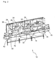
- FIG. 2 shows a perspective longitudinal section of the drying plant 12 with the components therein for drying
- each of the modules 10a, 10b and 10c shown has substantially three housing sections.
- the conveyor belt 16 and the nozzles for blowing off the bottles 30.
- a siphon for noise reduction is provided at the bottom of a funnel or tub-shaped water drain and possibly at its lowest point.
- the dripping and / or draining water from the bottles or other parts of the module 10 is collected and removed.
- the air supply opening 26 Above the central area and separated by a horizontal partition wall 32 are the air supply opening 26, an air supply unit 34 and a leading to the air discharge opening 28 air discharge channel 36.
- the formed as a muffler air discharge channel 36 and its components are based on the FIGS. 4 and 5 explained in more detail.
- the detailed view of the Fig. 3 shows the first drying module 10a of the drying plant 12 with its essential components.
- the arranged below the conveyor belt 16 tray 38 collects water and performs this if necessary via a sound-absorbing labyrinthine (not shown) or a siphon.
- a first set of nozzles 40 in the form of four pairs of obliquely upwardly directed round nozzles, which are directed towards the neck area of the bottles 30 and blow them upwards.
- the round nozzles of the first nozzle set 40 are respectively arranged on both sides of the conveyor belt 16.
- the distance of the round dies to the conveyor belt as well as their vertical position and / or their blowing angle can be varied in order to equally allow different conveyor belt widths and different sizes, ie bottle widths and heights.
- a second set of nozzles 42 in the form of stepped flat nozzles adjoins, which are arranged one after another in the conveying direction of the bottles 30 with each other. Two such outflow surfaces are each arranged opposite to both sides of the conveyor belt 16.
- the second nozzle set 42 can preferably also be adjusted in its respective distance to the conveyor belt 16 and possibly in its inclination and / or in height.
- Both nozzle sets 40 and 42 are fed via air ducts 44 from the above the horizontal partition wall 32 arranged air supply unit 34, which in the illustrated embodiment, an axial fan 46 and an electric
- Drive motor 48 for driving the fan 46 includes. Alternatively, a radial fan or other suitable design can be used.
- the drive motor 48 may optionally be coupled via a drive belt, via a transmission or via a direct axial connection to the blower 46.
- the blower 46 is preceded by an intake air filter 50, which filters the intake air and, if necessary, act as Ansauggeräuschdämpfer or can be coupled with an additional Ansauggeräuschdämpfer.
- a suitable sensor (not shown) may be arranged, which detects the pressure difference between the environment and the pressure prevailing in the air line 44 and provides an output signal to a control unit for the drive motor 48.
- a control unit for the drive motor 48.
- the air supply unit 34 is separated from the air discharge duct 36 by a vertical partition 52 which has a lower opening 54 which breaks through the horizontal partition 32 and establishes an open air connection to the central area with the drying nozzles 40, 42.
- the longitudinal section of the Fig. 4 shows on the two opposite vertical side walls 56 of the channel 36 respectively sound-damping elements 58 are arranged, which are formed by obliquely arranged to the channel longitudinal direction of the structured plates 60.
- the plates 60 have coarse metal grids 62 and a filling 64 of metal wool. The sound-absorbing effect thus results from a reflection damping by the deflection of the exhaust air and an absorption damping by the metal wool. Possibly.
- the inner walls of the air discharge channel 36 may have a structured surface and / or be lined with sound-absorbing material.
- an additional suction can be provided, for example.
- one or two suction fan 68 By one or two suction fan 68.
- the top view of Fig. 5 shows an embodiment of the air discharge channel 36, which is equipped with two suction fans 68.
- the modules 10 of the drying system 12 may optionally be supported on vertical supports 70 and possibly height-adjustable feet 72 on the ground.
- the supports 70 suitably form at the same time a supporting frame, which is stabilized by cross struts on which the side walls are held.
- the housing 14 of the modules 10 may also be designed differently than shown.
- the largely identically constructed modules 10 may each have different sets of nozzles.
- the second module 10b comprises a third nozzle set 74, which blows the bottles 30 from below.
- the third module 10c has a fourth nozzle set 76 and a fifth nozzle set 78. While the fifth nozzle set 78 corresponds to the first set of nozzles 40 from the structure and its location near the output port 20 for the conveyor belt 16 and the bottles 30, the fourth nozzle set 76 having obliquely upwardly extending narrow nozzles is for blowing down the bottles 30 from bottom to top intended.
- an air lock 22 is arranged (see. Fig. 1 ).
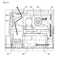
- FIG. 6 shows the flow path within a drying module 10, which - starting from the fan 46 via the air line 44 and the second nozzle set 42 - describes an annular course in the direction of the air discharge channel 36.
- the flow deflection upwards in the direction of the air discharge channel 36 is favored on the one hand by the air exiting at the first set of nozzles 40. Since the first set of nozzles 40 is disposed directly below the air discharge channel 36 and the air exiting from the nozzles obliquely upward, the air emerging from the second nozzle set 42 in the area above the conveyor belt 16 to the left in the direction of the first nozzle set 40 and transported there upwards in the direction of the air discharge channel 36.
- Reference numeral 80 denotes the dry supply air conveyed from the blower 46 through the air line to the nozzle sets 40, 42, while the reference numeral 82 designates the moist exhaust air conveyed through the air discharge passage 36.
- the illustrated flow control ensures that only a very small proportion of the moist exhaust air 82 can escape through the inlet opening 18 or through the outlet opening 20.
- the soundproofing is optimized by the fact that the the majority of the moist exhaust air 82 is passed through the trained as a muffler channel 36 to the outside.
Landscapes
- Engineering & Computer Science (AREA)
- Mechanical Engineering (AREA)
- General Engineering & Computer Science (AREA)
- Drying Of Solid Materials (AREA)
Applications Claiming Priority (1)
| Application Number | Priority Date | Filing Date | Title |
|---|---|---|---|
| DE102008004774A DE102008004774A1 (de) | 2008-01-16 | 2008-01-16 | Vorrichtung und Verfahren zur Trocknung von Gegenständen, insbesondere von Flüssigkeitsbehältern |
Publications (2)
| Publication Number | Publication Date |
|---|---|
| EP2080971A2 true EP2080971A2 (fr) | 2009-07-22 |
| EP2080971A3 EP2080971A3 (fr) | 2011-08-03 |
Family
ID=40548762
Family Applications (1)
| Application Number | Title | Priority Date | Filing Date |
|---|---|---|---|
| EP20080171534 Withdrawn EP2080971A3 (fr) | 2008-01-16 | 2008-12-12 | Dispositif et procédé destinés au séchage d'objets, notamment de récipients à liquides |
Country Status (6)
| Country | Link |
|---|---|
| US (1) | US20090178296A1 (fr) |
| EP (1) | EP2080971A3 (fr) |
| JP (1) | JP2009168440A (fr) |
| KR (1) | KR20090079174A (fr) |
| CN (1) | CN101487659A (fr) |
| DE (1) | DE102008004774A1 (fr) |
Cited By (4)
| Publication number | Priority date | Publication date | Assignee | Title |
|---|---|---|---|---|
| EP2319770A1 (fr) * | 2009-11-09 | 2011-05-11 | Krones AG | Dispositif et procédé destinés à l'étiquetage de récipients remplis |
| DE102010030824A1 (de) | 2010-07-01 | 2012-01-05 | Krones Aktiengesellschaft | Flaschentrocknung mit Vibration |
| CN104596218A (zh) * | 2014-12-09 | 2015-05-06 | 广州市风华正茂包装材料有限公司 | 一种新型烘干机 |
| DE102014206672A1 (de) * | 2014-04-07 | 2015-10-08 | Krones Aktiengesellschaft | Vorrichtung und Verfahren zur Herstellung von Gebinden aus untereinander durch ein Haftmittel verklebten Artikeln |
Families Citing this family (17)
| Publication number | Priority date | Publication date | Assignee | Title |
|---|---|---|---|---|
| DE102009037188A1 (de) * | 2009-08-12 | 2011-02-17 | Krones Ag | Reinigungsmaschine |
| DE102011054683B4 (de) | 2011-10-21 | 2023-11-09 | Krones Aktiengesellschaft | Trocknungsvorrichtung für Behälter und Verfahren zum Reinigen einer solchen Trocknungsvorrichtung |
| CN103182645B (zh) * | 2013-03-01 | 2015-05-20 | 杭州沃镭科技有限公司 | 一种汽车空气干燥器装配及检测生产线 |
| CN103175388A (zh) * | 2013-03-20 | 2013-06-26 | 佛山市潜信达酿酒包装设备有限公司 | 风刀式低噪音节能干瓶机 |
| CN106546083A (zh) * | 2015-06-23 | 2017-03-29 | 胡妍 | 酒瓶烘干设备 |
| EP3329199B1 (fr) * | 2015-07-30 | 2020-02-05 | Siti - B&T Group S.p.A. | Dispositif de sèchage pour des produits céramiques |
| CN106766836A (zh) * | 2016-12-16 | 2017-05-31 | 无锡同方人工环境有限公司 | 风机盘管换热器水检自动吹水装置 |
| CN107036421A (zh) * | 2017-05-31 | 2017-08-11 | 成都璐城科技有限公司 | 一种新型中药材烘干设备 |
| CN107178976A (zh) * | 2017-07-06 | 2017-09-19 | 中国大冢制药有限公司 | 安瓿干燥室 |
| CN107965998A (zh) * | 2017-12-27 | 2018-04-27 | 山东琦泉能源科技有限公司 | 通风干燥装置 |
| DE112019002259B4 (de) * | 2018-05-01 | 2022-07-07 | Universal Can Corporation | Trocknungseinrichtung und Verfahren zur Herstellung eines Dosenkörpers |
| JP2020180761A (ja) * | 2019-04-26 | 2020-11-05 | 春日電機株式会社 | 防音装置 |
| CN110631345B (zh) * | 2019-09-23 | 2023-12-05 | 常州捷佳创精密机械有限公司 | 烘干装置及烘干装置的控制方法 |
| CN110762989A (zh) * | 2019-11-01 | 2020-02-07 | 邳州都康生物科技有限公司 | 一种饮用水生产用干燥设备 |
| US11248841B2 (en) * | 2019-12-18 | 2022-02-15 | Dari-Tech, Inc. | Coand{hacek over (a)}-effect vegetable material dryer |
| CN115493387B (zh) * | 2022-08-12 | 2023-09-22 | 麦卡尼食品设备(中山)有限公司 | 一种可加热可制冷的干燥机 |
| CN116067126B (zh) * | 2023-03-06 | 2023-06-16 | 临朐天利生物制品有限公司 | 生产用高效干燥装置 |
Citations (2)
| Publication number | Priority date | Publication date | Assignee | Title |
|---|---|---|---|---|
| DE1201528B (de) * | 1959-06-25 | 1965-09-23 | Bahco Ab | Geraeuschdaempfer fuer Ventilationsaggregate |
| WO2007035274A2 (fr) | 2005-09-15 | 2007-03-29 | Steris Inc. | Systeme de lavage en tunnel offrant une efficacite accrue |
Family Cites Families (30)
| Publication number | Priority date | Publication date | Assignee | Title |
|---|---|---|---|---|
| NL134387C (fr) * | ||||
| DE897615C (de) * | 1943-04-10 | 1953-11-23 | Aeg | Labyrinthschalldaempfer fuer das Ansauggeraeusch von Verdichtern und Geblaesen |
| US3228113A (en) * | 1960-08-18 | 1966-01-11 | John J Fannon Products Co | Heating apparatus and method |
| US3762489A (en) * | 1971-04-19 | 1973-10-02 | Caterpillar Tractor Co | Acoustical engine enclosure for earthmoving vehicles |
| US3820627A (en) * | 1972-08-28 | 1974-06-28 | Lockheed Aircraft Corp | Apparatus for noise and air pollution abatement |
| CH607201A5 (en) * | 1975-04-11 | 1978-11-30 | Christian Louis Grandchamps | Noise baffle for air duct |
| FR2444908A1 (fr) * | 1978-12-20 | 1980-07-18 | Lemaire Freres | Machine a secher les bouteilles pleines |
| US4392417A (en) * | 1979-04-30 | 1983-07-12 | Mcquay-Perfex Inc. | Variable dead band pressure control system |
| EP0185980B1 (fr) * | 1984-12-27 | 1995-03-01 | Teijin Limited | Appareil d'enrichissement d'oxygène |
| US4852271A (en) * | 1988-03-04 | 1989-08-01 | Owens-Illinois Glass Container Inc. | Preheat oven for glass containers |
| US4887366A (en) * | 1988-06-16 | 1989-12-19 | Kuhl Henry Y | Article drying apparatus with adjustable drying plenum means |
| US5140819A (en) * | 1989-09-28 | 1992-08-25 | Sundstrand Corporation | Turbine inlet silencer |
| JPH0651787U (ja) * | 1992-10-06 | 1994-07-15 | 株式会社和泉製作所 | 乾燥装置 |
| US5357648A (en) * | 1993-04-16 | 1994-10-25 | Valiant Machine & Tool, Inc. | Part washing and drying machine |
| DE4430486A1 (de) * | 1994-08-27 | 1996-02-29 | Schuebler Fahrzeugtechnik Gmbh | Abluftschalldämpfer für Silos und Silofahrzeuge |
| JPH09292175A (ja) * | 1996-04-26 | 1997-11-11 | Daisoo:Kk | 容器乾燥装置 |
| DE29718687U1 (de) * | 1997-10-22 | 1997-12-11 | Schäfer Werke GmbH, 57290 Neunkirchen | Schrank aus Metallblech |
| ATE256275T1 (de) * | 1999-02-09 | 2003-12-15 | Cames Snc Di Colla G & Sardi G | Vorrichtung zum trocknen von flaschen |
| US20020040643A1 (en) * | 2000-09-25 | 2002-04-11 | Ware Gerald J. | Desiccation apparatus and method |
| DE10121940C1 (de) * | 2001-05-05 | 2003-01-23 | Howatherm Klimatech Gmbh | Absorptionsschalldämpfer für raumlufttechnische Anlagen |
| US20030130887A1 (en) * | 2001-10-03 | 2003-07-10 | Thurston Nathaniel | Non-deterministic method and system for the optimization of a targeted content delivery |
| JP3709865B2 (ja) * | 2002-10-10 | 2005-10-26 | 春日電機株式会社 | 除水機 |
| DE102004003797A1 (de) * | 2004-01-26 | 2005-08-18 | Meiko Maschinenbau Gmbh & Co. Kg | Geschirrspülautomat mit regelbarer Wärmrückgewinnung |
| JP3879086B2 (ja) * | 2004-06-03 | 2007-02-07 | 春日電機株式会社 | 除水機 |
| JP2006307690A (ja) * | 2005-04-27 | 2006-11-09 | Kioritz Corp | 動力ユニット |
| US20070100690A1 (en) * | 2005-11-02 | 2007-05-03 | Daniel Hopkins | System and method for providing targeted advertisements in user requested multimedia content |
| US20070113243A1 (en) * | 2005-11-17 | 2007-05-17 | Brey Thomas A | Targeted advertising system and method |
| JP4800087B2 (ja) * | 2006-04-07 | 2011-10-26 | 近藤工業株式会社 | 印刷紙の熱風乾燥装置 |
| US8074372B2 (en) * | 2007-05-08 | 2011-12-13 | Illinois Tool Works Inc. | Power drying system |
| ITPR20070099A1 (it) * | 2007-12-21 | 2009-06-22 | Europool Srl | Modulo per l'asciugatura di superfici esterne di contenitori |
-
2008
- 2008-01-16 DE DE102008004774A patent/DE102008004774A1/de not_active Withdrawn
- 2008-12-12 EP EP20080171534 patent/EP2080971A3/fr not_active Withdrawn
-
2009
- 2009-01-14 CN CNA2009100005235A patent/CN101487659A/zh active Pending
- 2009-01-15 US US12/321,100 patent/US20090178296A1/en not_active Abandoned
- 2009-01-15 KR KR1020090003439A patent/KR20090079174A/ko not_active Withdrawn
- 2009-01-16 JP JP2009007961A patent/JP2009168440A/ja active Pending
Patent Citations (2)
| Publication number | Priority date | Publication date | Assignee | Title |
|---|---|---|---|---|
| DE1201528B (de) * | 1959-06-25 | 1965-09-23 | Bahco Ab | Geraeuschdaempfer fuer Ventilationsaggregate |
| WO2007035274A2 (fr) | 2005-09-15 | 2007-03-29 | Steris Inc. | Systeme de lavage en tunnel offrant une efficacite accrue |
Cited By (8)
| Publication number | Priority date | Publication date | Assignee | Title |
|---|---|---|---|---|
| EP2319770A1 (fr) * | 2009-11-09 | 2011-05-11 | Krones AG | Dispositif et procédé destinés à l'étiquetage de récipients remplis |
| EP2361835A1 (fr) * | 2009-11-09 | 2011-08-31 | Krones AG | Dispositif et procédé destinés à l'étiquetage de récipients remplis |
| EP2361835B1 (fr) | 2009-11-09 | 2018-03-14 | Krones AG | Dispositif et procédé destinés à l'étiquetage de récipients remplis |
| EP2361835B2 (fr) † | 2009-11-09 | 2023-10-04 | Krones AG | Dispositif et procédé destinés à l'étiquetage de récipients remplis |
| DE102010030824A1 (de) | 2010-07-01 | 2012-01-05 | Krones Aktiengesellschaft | Flaschentrocknung mit Vibration |
| DE102014206672A1 (de) * | 2014-04-07 | 2015-10-08 | Krones Aktiengesellschaft | Vorrichtung und Verfahren zur Herstellung von Gebinden aus untereinander durch ein Haftmittel verklebten Artikeln |
| CN104596218A (zh) * | 2014-12-09 | 2015-05-06 | 广州市风华正茂包装材料有限公司 | 一种新型烘干机 |
| CN104596218B (zh) * | 2014-12-09 | 2016-10-12 | 广州市风华正茂包装材料有限公司 | 一种烘干机 |
Also Published As
| Publication number | Publication date |
|---|---|
| KR20090079174A (ko) | 2009-07-21 |
| US20090178296A1 (en) | 2009-07-16 |
| JP2009168440A (ja) | 2009-07-30 |
| DE102008004774A1 (de) | 2009-07-23 |
| CN101487659A (zh) | 2009-07-22 |
| EP2080971A3 (fr) | 2011-08-03 |
Similar Documents
| Publication | Publication Date | Title |
|---|---|---|
| EP2080971A2 (fr) | Dispositif et procédé destinés au séchage d'objets, notamment de récipients à liquides | |
| EP1931480B2 (fr) | Dispositif et procede destines a separer la peinture humide perdue lors de la pulverisation | |
| EP0824607B2 (fr) | Procede et dispositif permettant d'identifier et de separer des corps etrangers contenus dans un materiau fibreux | |
| DE69701803T2 (de) | Verfahren und vorrichtung zum schützen einer arbeitsplatte | |
| EP1661634A2 (fr) | Appareil pour le nettoyage sans contact d'un convoyeur et ensemble pour transporter et/ou stocker des articles en forme de baguette comprenant un appareil pour le nettoyage sans contact d'un convoyeur | |
| EP1979103B1 (fr) | Dispositif de nettoyage de bande | |
| EP0604925B1 (fr) | Procédé pour la conduite d'air dans un compartiment et dispositif pour le traitement de petites pièces | |
| DE102012223402A1 (de) | Direktdruckmaschine mit Verkleidung | |
| EP3165635A1 (fr) | Dispositif d'étirage | |
| DE3419028C2 (fr) | ||
| EP3730022B1 (fr) | Élément filtrant | |
| WO2008071259A1 (fr) | Installation pour encoller des fibres pour la production de panneaux de fibres | |
| EP3533912B1 (fr) | Dispositif de stockage pour matière fibreuse doté d'une unité de nettoyage | |
| WO2011131539A1 (fr) | Installation mécanique pour le traitement thermique de pièces | |
| DE19882237B4 (de) | Füllmaschine zum sterilen Befüllen und Verschließen von Verpackungsbehältern | |
| EP1082914B1 (fr) | Dispositif de réduction du niveau de bruit des machines de production soumises à l'action d'un flux d'air dans l'industrie du tabac | |
| DE19822537A1 (de) | Reinigungsvorrichtung für Karosserien von Fahrzeugen | |
| DE102016117383B4 (de) | Sichter | |
| DE3833860A1 (de) | Vorrichtung zur entsorgung von erzeugern staub- und/oder spanfoermiger abfaelle | |
| AT506149A1 (de) | Fördervorrichtung für kleinteile | |
| EP1929886B1 (fr) | Installation de traitement pour produits alimentaires, en particulier saucisses crues et produits salés crus | |
| DE19916233C1 (de) | Walzgerüst | |
| EP1114282A1 (fr) | Procede et dispositif permettant de proteger les personnes et/ou produits de particules en suspension dans l'air | |
| DE102012010030B4 (de) | Verfahren und vorrichtung zur trennung eines heterogenen materialstroms in mindestens zwei materialfraktionen | |
| DE4009442A1 (de) | Duese fuer das trocknen von glastafeln |
Legal Events
| Date | Code | Title | Description |
|---|---|---|---|
| PUAI | Public reference made under article 153(3) epc to a published international application that has entered the european phase |
Free format text: ORIGINAL CODE: 0009012 |
|
| AK | Designated contracting states |
Kind code of ref document: A2 Designated state(s): AT BE BG CH CY CZ DE DK EE ES FI FR GB GR HR HU IE IS IT LI LT LU LV MC MT NL NO PL PT RO SE SI SK TR |
|
| AX | Request for extension of the european patent |
Extension state: AL BA MK RS |
|
| PUAL | Search report despatched |
Free format text: ORIGINAL CODE: 0009013 |
|
| AK | Designated contracting states |
Kind code of ref document: A3 Designated state(s): AT BE BG CH CY CZ DE DK EE ES FI FR GB GR HR HU IE IS IT LI LT LU LV MC MT NL NO PL PT RO SE SI SK TR |
|
| AX | Request for extension of the european patent |
Extension state: AL BA MK RS |
|
| 17P | Request for examination filed |
Effective date: 20111107 |
|
| 17Q | First examination report despatched |
Effective date: 20120103 |
|
| AKX | Designation fees paid |
Designated state(s): DE FR GB |
|
| RIC1 | Information provided on ipc code assigned before grant |
Ipc: F26B 21/00 20060101ALI20150121BHEP Ipc: F26B 21/06 20060101ALI20150121BHEP Ipc: F26B 15/18 20060101AFI20150121BHEP |
|
| GRAP | Despatch of communication of intention to grant a patent |
Free format text: ORIGINAL CODE: EPIDOSNIGR1 |
|
| INTG | Intention to grant announced |
Effective date: 20150326 |
|
| RIN1 | Information on inventor provided before grant (corrected) |
Inventor name: FIEGLER, RUDOLF Inventor name: EICHHAMMER, TOBIAS Inventor name: DUENZINGER, BERNHARD |
|
| STAA | Information on the status of an ep patent application or granted ep patent |
Free format text: STATUS: THE APPLICATION IS DEEMED TO BE WITHDRAWN |
|
| 18D | Application deemed to be withdrawn |
Effective date: 20150806 |